awesome! I do have a table saw. I will try it once more now that things are on the up and up and if that fails because they’re too long on the angle, then I will definitely use the table saw.
I cut mine for the LowRider 3 on the Primo, flipping them over after cutting half of them with the help of dowels, did the same for the LR4 struts, works flawlessly.
interesting!! thanks for the idea as well.
I can’t for the life of me find my thread where I gave detailed information on how to do it…
here?
Yes, thanks a lot! I thought it had it’s own thread. Glad you found it. ![]()
Search dowel @Tokoloshe
if you ever need to find it again ![]()
@Jason_Fair
Exciting news! Thanks for keeping us updated!
I looked for “peg @Tokoloshe”… ![]()
How do I “partially” make a tool path in estlcam?
You click on engrave, set the line to outside and draw it manually (I think it’s a hand icon).
Might be time to remind us all that we can put keyword tags in a post header.
I cut mine in an angle due to it being my only option at the time. There might be better ways of dealing with this and indeed might not be the preferred option.
Firstly, I attached the plywood to the spoilboard where I knew the lowrider could reach. Thereafter, I zeroed the lowrider on roughly where the lower corner of the strut would be (with a margin on the plywood included) then checked the position of the other end of the plywood (with same margin). I changed the grid on estlcam to be exactly this figure and aligned the strut to face the corner of the grid, in addition I needed to (re-)set zero marker on the lower edge of the strut. Before running, I tested with an “air cut” with the outer edge of the strut only, running it above the plywood and checking that it was rightly aligned. Only after I was sure it was angled right, I proceeded with cutting the strut.
I just finished cutting my 3 struts on diagonal. I had trouble with workpiece hold downs with double sided tape, so I screwed the ends down where the bit wasnt going to be. Very close to disassembling it to mount the struts!
One trick is to ensure the screw holes are the first tool path cut, then as it drills the holes, you can put a small screw in them (as long as the head is much lower than your clearance plane.) That way you can use the screw holes in the part as hold downs, and eliminate even the need for tabs.
At first I did this with a pause to allow me to mess with it, but for simple situations, I now just sneak a couple of screws in behind the machines as it moves. I think I picked that up from Doug on one of his videos.
That would have been a brilliant idea! I thought about that after the fact too but figured two in each end would help because that is where I had the issues.
I might have to do another cut of them because I didnt cut the triangles out of the struts which will make fastening the hardboard down with the nuts very difficult I think. I just wanted to see a couple successful cuts under my belt lol.
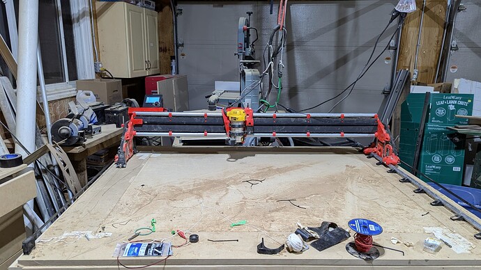
Well, I have completed the struts and I have made my first cuts. I made a donut for my dust collector. Unfortunately it was not exactly round. It was not oval necessarily but it was off by a couple of mm one way vs the other.
Here is the video of it cutting: https://www.youtube.com/watch?v=kC6tydpZIEQ
Here it is in all it’s glory:
Is there anything you guys can think of that would be skewing my circles from being round at all? Belt tightness? The X is definitely tight for sure, and so are the Ys.
Also, how do you guys change end mills without making the cnc go off from it’s coordinates? Maybe I am tightening my collet too tight?
Thanks guys. Getting really excited.
Jason
So there are at least four things to check for calibrating your awesome new machine!
One is to use it to mark each corner (felt tip on machine, marking on painters tape in corners), and then measure the diagonals to check for square. Mostly likely, the two numbers won’t match when you start, but you can get them very close to matching when you’re done. I think there is info about this in docs somewhere. @JamieK offers a software tool that will generate the gcode for making your marks. I posted a video about how I (instead) used a sharp pointy v-carve bit to actually poke small holes in the tape (an idea I got from Ryan’s video). The pen marker method is easier. Then you can use either hardware adjustment of your Y end stops to correct the skew, or software adjustment of the amount of pull off from a given Y end stop after homing to correct the skew, or both. Some of us do hardware adjustment to get close, and then software for finer adjustment to finish. The larger you can draw the rectangle, the more accurate it will be.
Video: for making the adjustment using Marlin (which is firmware on, for instance, a BigTreeTech SKR board from Ryan):
Video: for making the adjustment using FluidNC (which is firmware on, for instance, a Jackpot board from Ryan):
Another thing is to make sure that when you tell it to travel “x” mm’s, that’s how many it travels. This matters most on long axes, so Y definitely, and probably X too. Again, the larger you can draw the line, the more accurate it will be. Then there is a software (well, firmware) adjustment (number of steps) to get it correct.
Another thing is to make sure your gantry is “trammed” to your table:
And finally, you can make sure your router is “normal” to your table, in which “normal” here is an engineering/mathematical term basically meaning perpendicular to the table in all directions in which it’s rotated. Ryan and others have provided designs on Printables for printing a thing to attach to your router, which can be slowly spun around, and the screw in the tip of the thing should always be touching the table all the way around the circle. This basically requires physically adjusting the angle by using some kind of tape as a shim.
For a Marlin / SKR: The best thing to do here, is to home your machine, and when you move it to your work origin, take careful note of the offset in X and Y, and then after you do a bit change, home again, and then move by the exact same amount of offset. Don’t forget you’ll need to re-probe for Z offset after a bit change!
For FluidNC/Jackpot: This is easy. Your board will remember the work origin you’ve “zeroed” to, even after rebooting the board! Just home after your bit change. Don’t forget you’ll need to re-probe for Z offset after a bit change! Then start your next op.
Ok! I was of the understanding that you probe for Zmin and then it just goes on it’s merry way on the gcode program. I havent got this far so I am hoping it works well for me! Thank you.
Also your videos are very helpful and I really appreciate your help with this. I am going to re square my cnc after the disassembly/reassembly!!


