Hello the community,
First, thanks to all the work and beautiful knowledge shared here.
I’m computer scientist, and shaper of surf - board - foil as hobbyist.
Most of the time, I’m learning the hard way, making lots of mistakes along the way, but I’m ok with that. I like also to try things a bit differently, even if it’s a failure at the end, my goal is to learn and have fun.
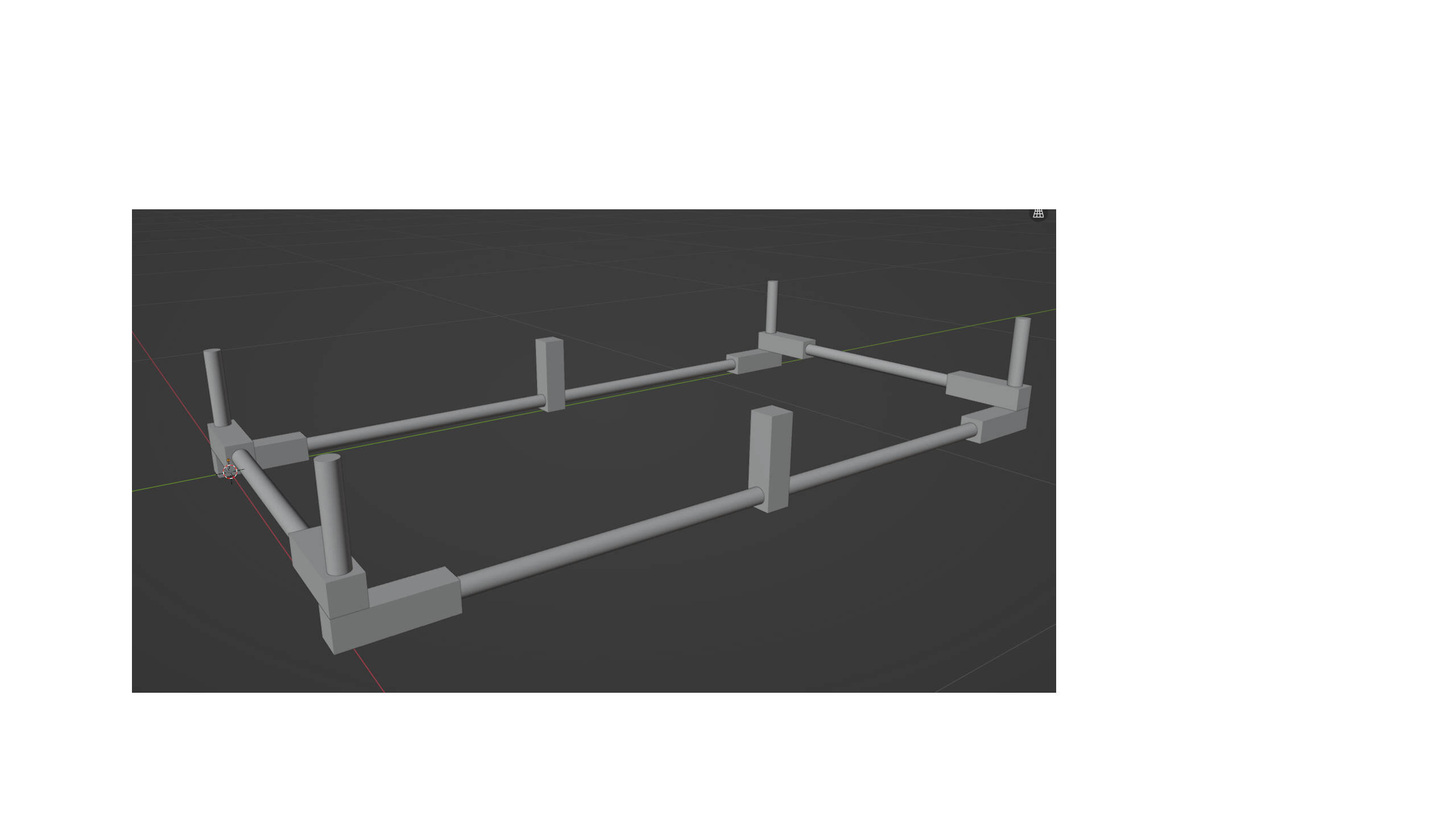
My MPCNC project will be called the HydroP.
HydroP will be very similar to the Drop in MPCNC of Mat.
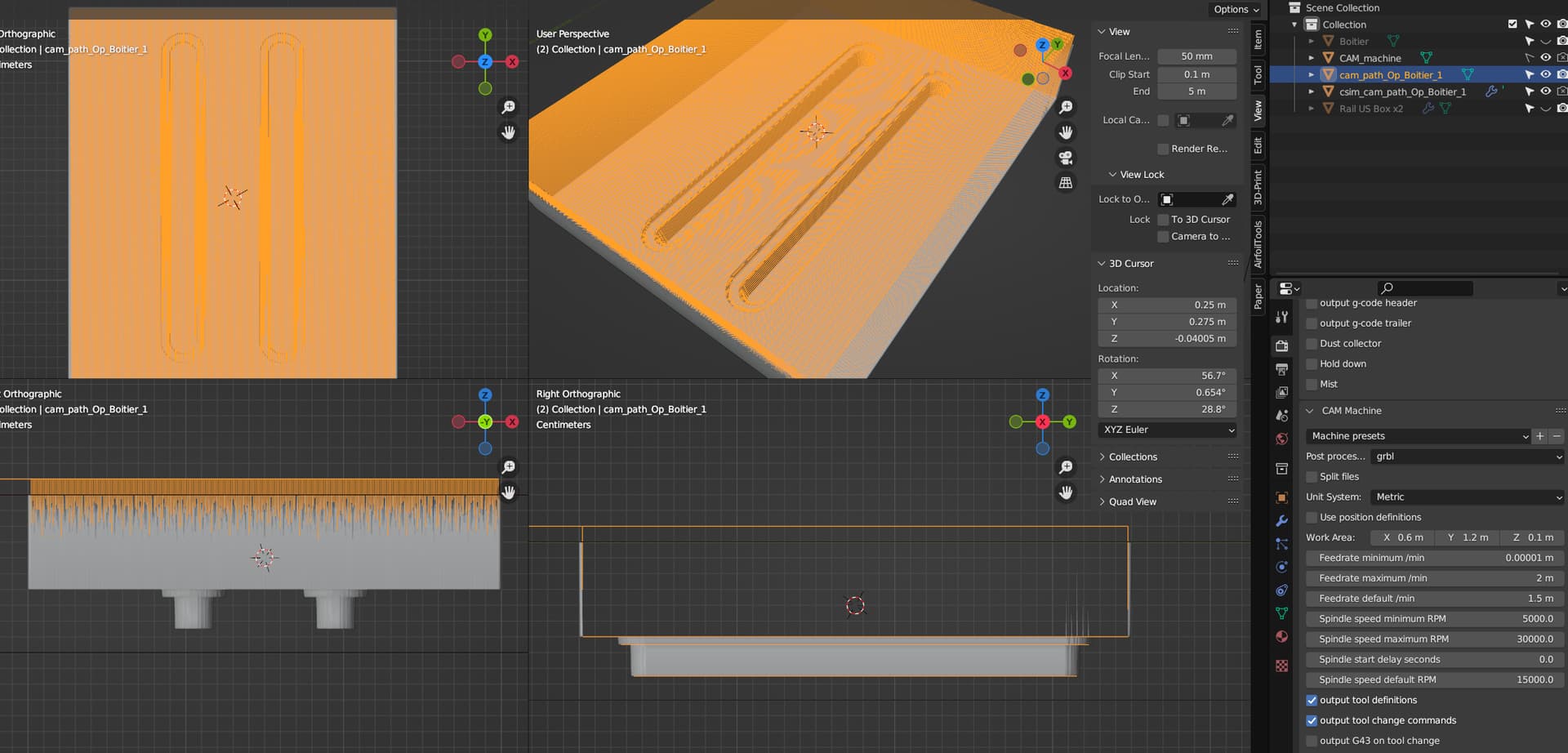
What I am trying to achieve : Designing a board or a piece of polystyrene or 90kg/m3 PVC on Blender, then using a slicer to generate GCode (Ultimaker) (maybe do some translation on this GCode?), GRBL and UGS machining the piece.
I am sourcing for now regular block of polystyrene (EPS or XPS), that are 1200x600x100mm maximum. I am planning to glue the multiple machined block together / make a stringer in the X axis for bigger piece / board.
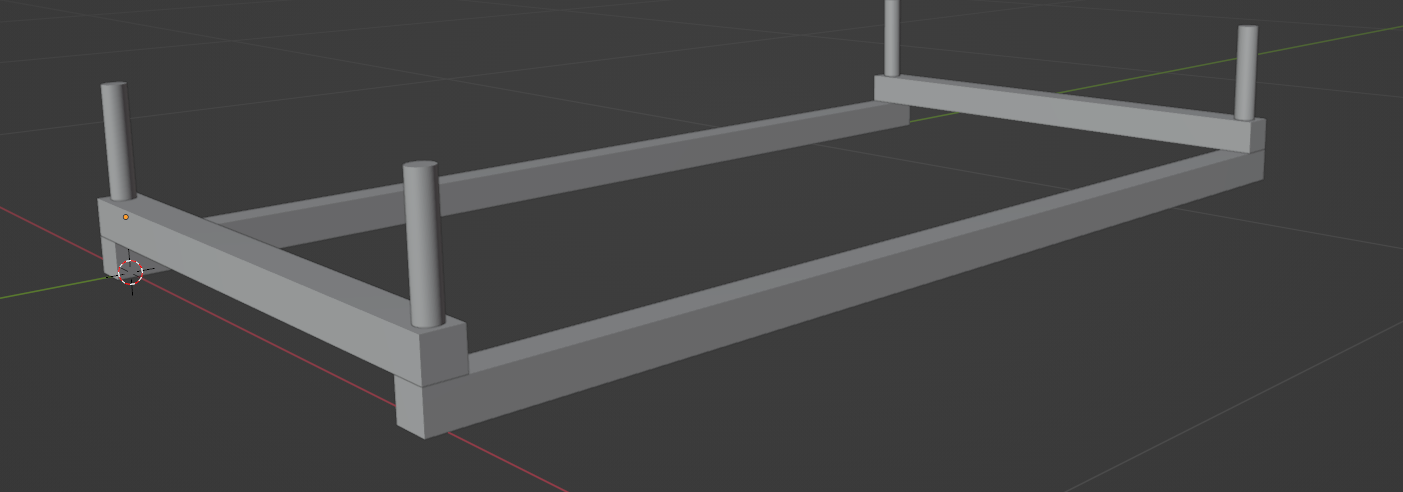
In order to have HydroP dropped in the polystyrene block, I am aiming at a 1100x500x100mm machining area, and make a table (again similar to the Mat one).
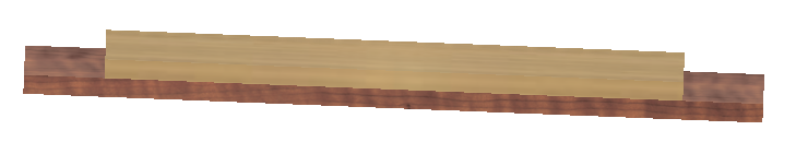
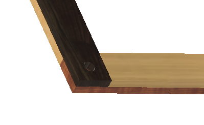
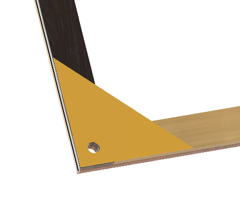
Because I am machining very light material, I hope the working area will be ok with a good wood custom table.
For the spindle, I ordered a 400W from Vevor ER11 52mm, and some 100m and 150mm meshes for milling of Dia 4 and 6mm.
For the electronic, simple Arduino Uno with CNC shield, motor driver for NEMA17, and GRBL.
Next steps :
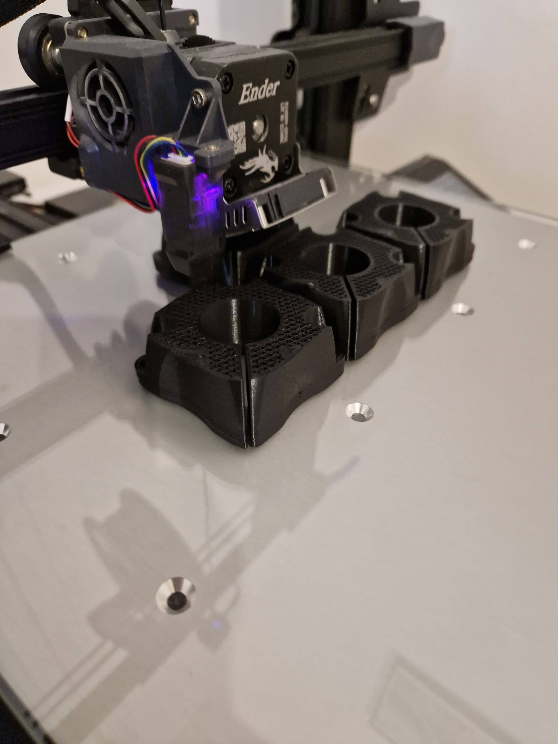
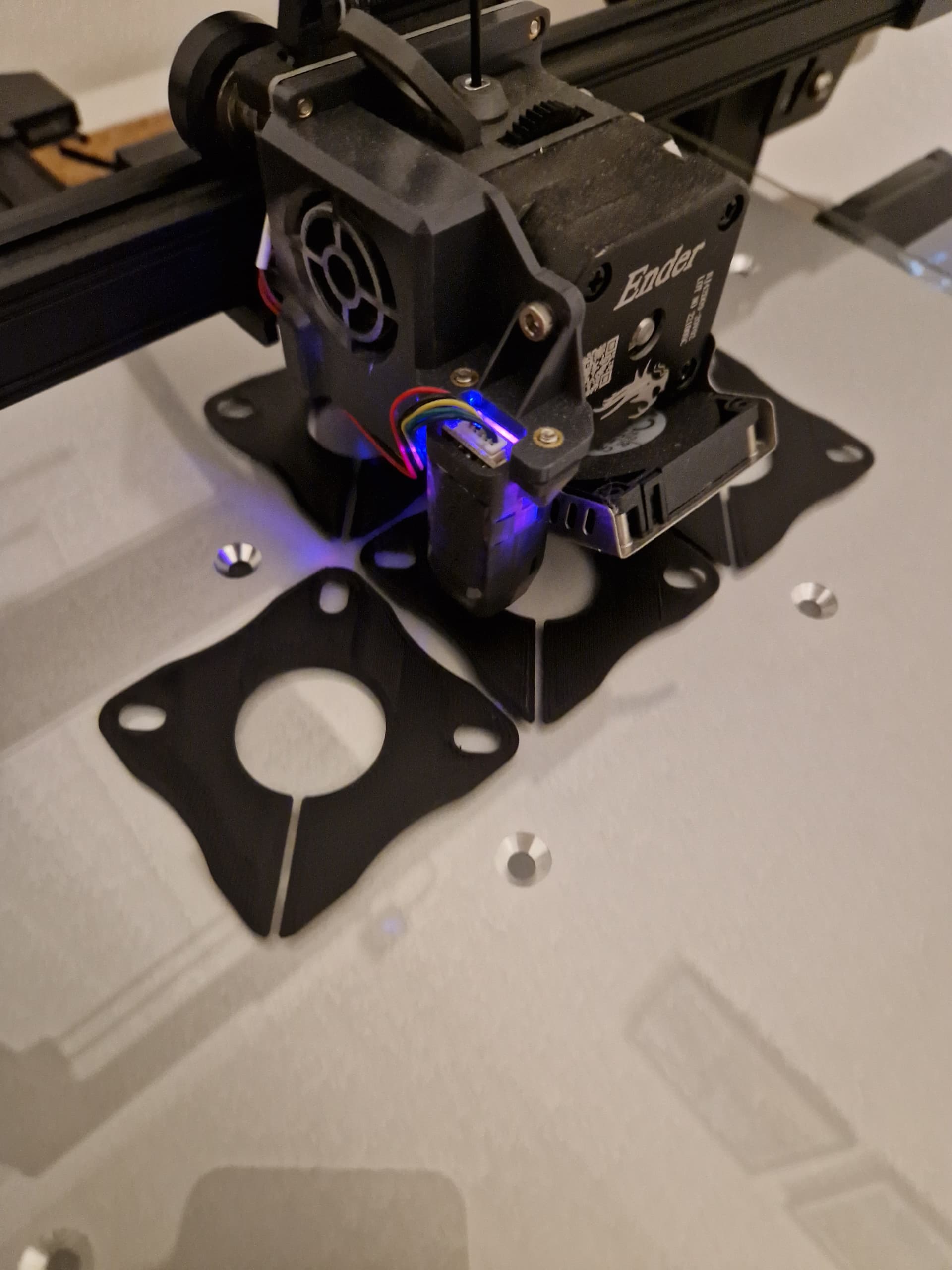
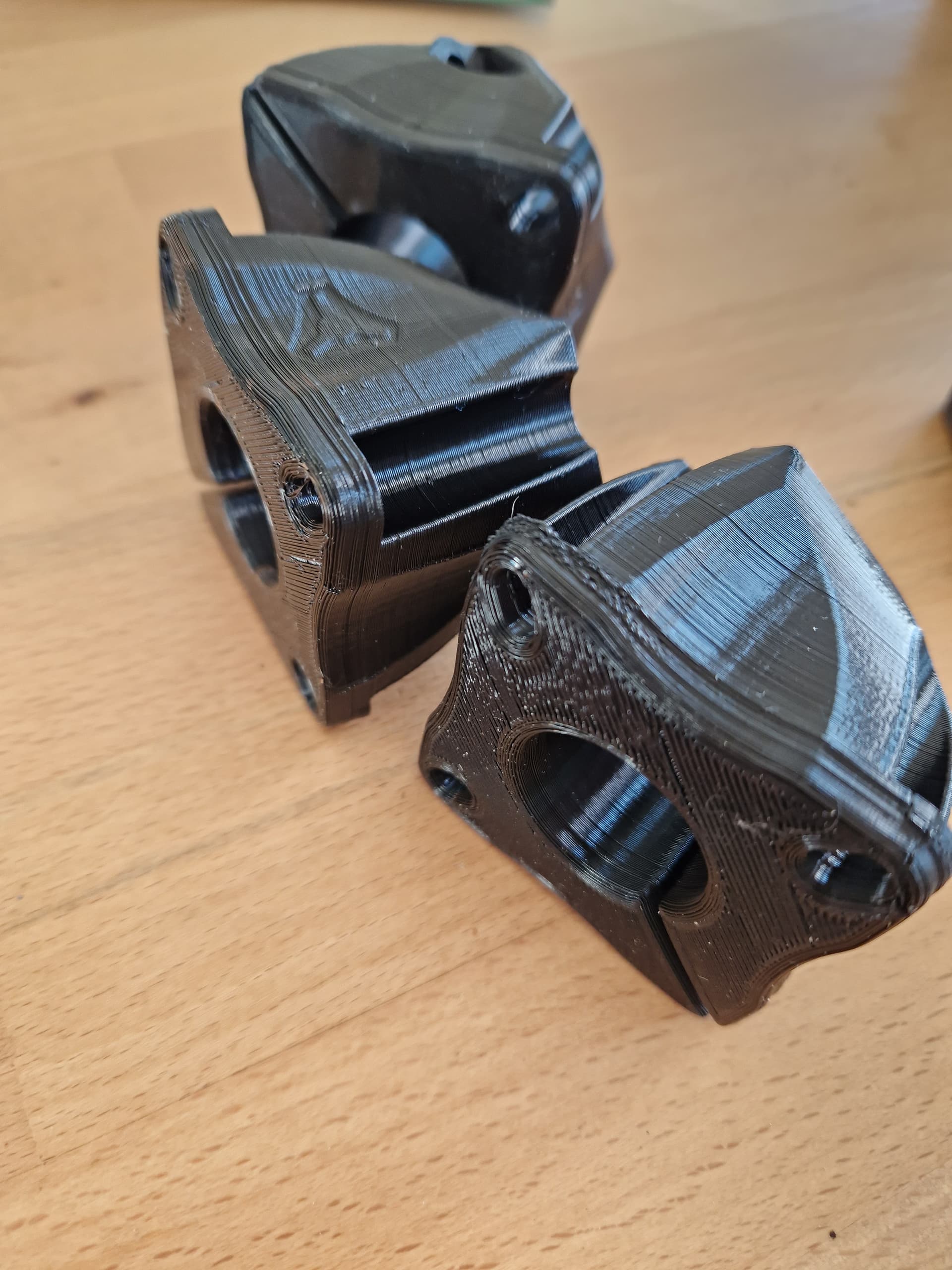
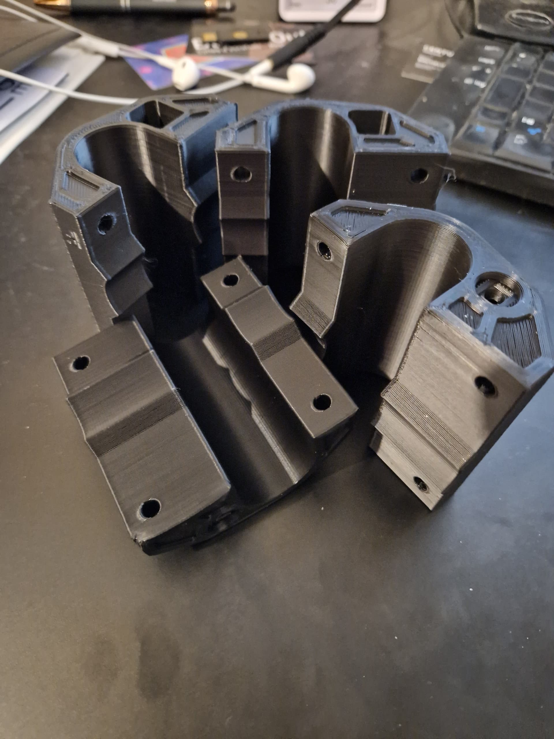
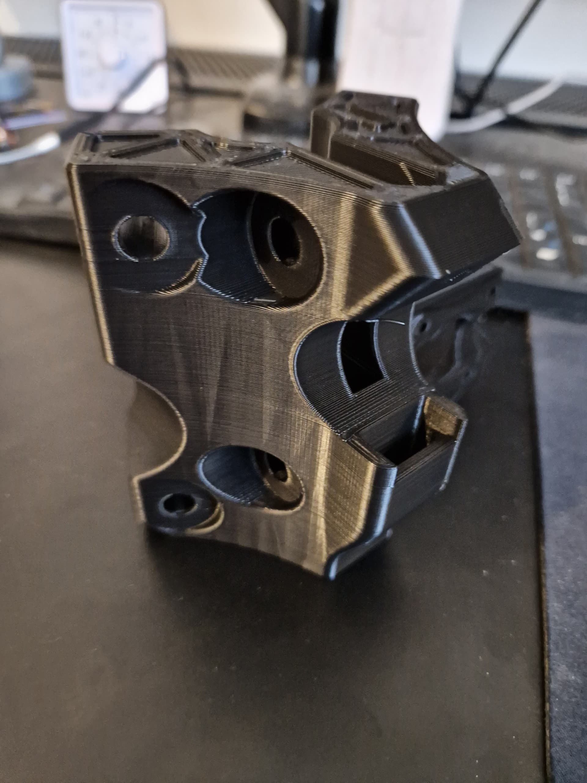
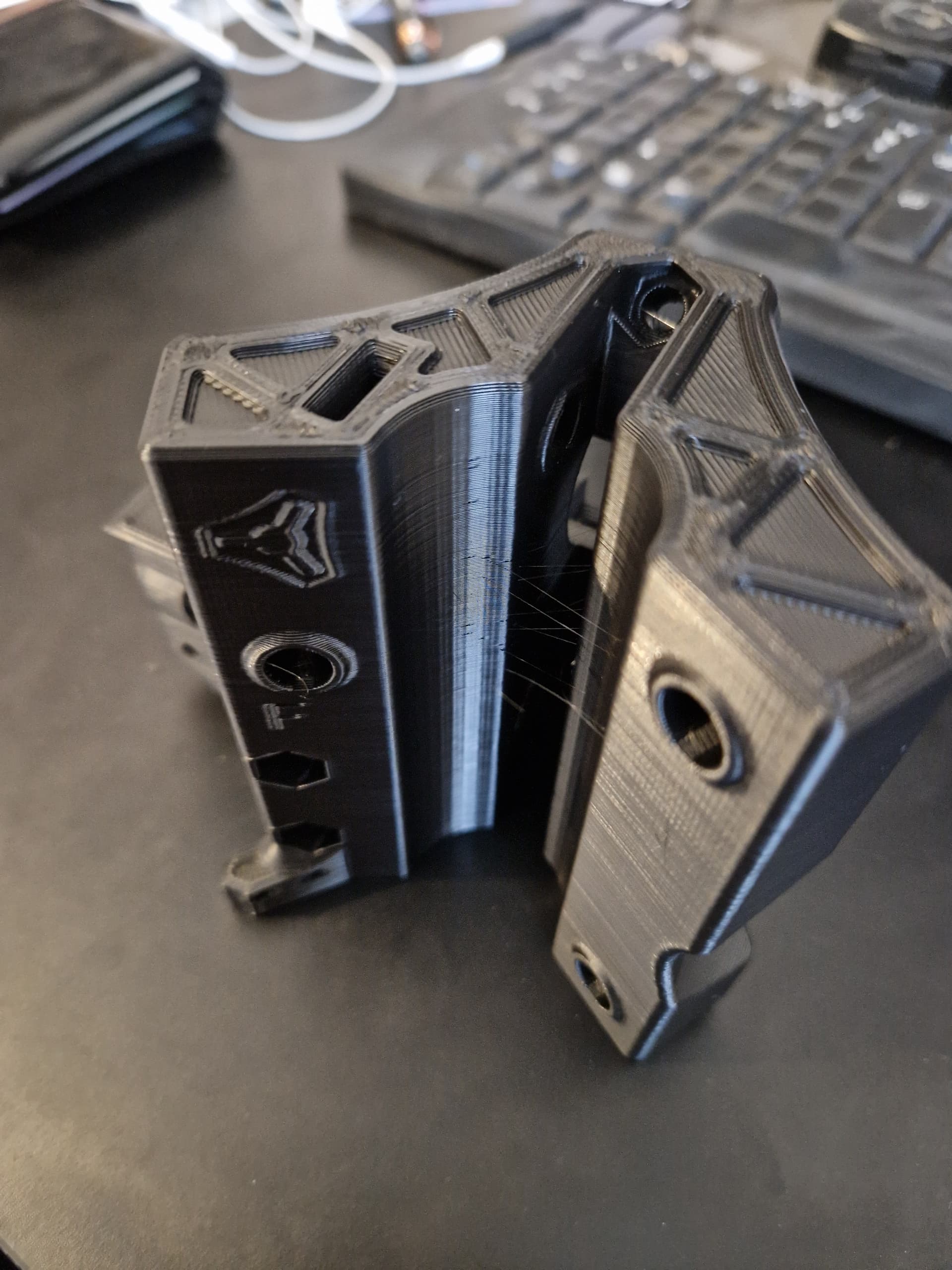
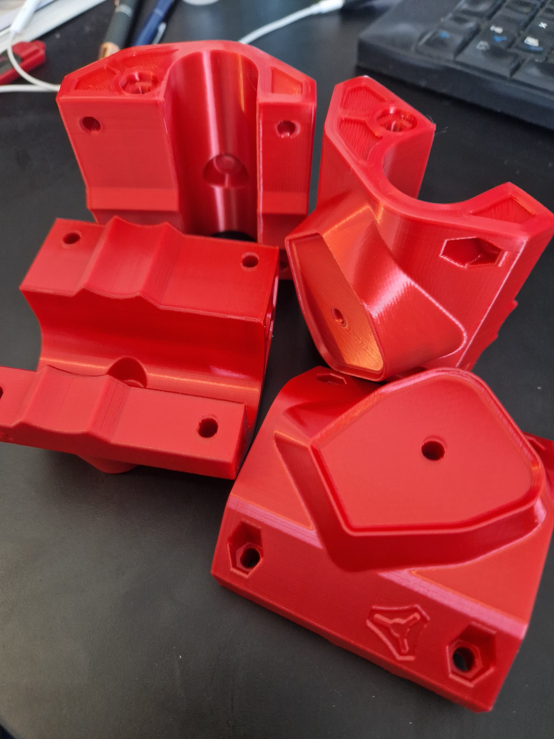
- printing time of the MPCNC with black and red PLA, like the original one on my Ender 3S+
- Read over and over the assembly instructions
- Assemble following instructions
- Make the table (squared, similar to Mat)
- Mount the Spindle
- Make some test on first polystyrene block
- Make a first small board

If you have any advice or if you think I’m making some error, please don’t hesitate to tell me, it will be highly appreciated.
And of course thanks Mat for your sharing of your CNC and work.