Yep, that is the one I have been using.
I will make the changes as see if that get us to the finish line.
Will take a few minutes, I removed the card and reset the VFD so I could use in in manual mode.
Some peoples children!
i might take a while to read and response im still working in the shop and im leaving the computer alone while its rendering something
Same response, The TX LED is flashing as it should the RX LED is on solid.
GGRRrrrrrr
from the spindle section in fluidnc wiki:
LEDs
"If you have Tx and Rx LEDs at the controller side the Tx should blink a few times per second. The Rx LED should blink right after. It does so so quickly that they may appear to blink at the same time. If the Rx LED stays on, try swapping A and B at the controller end. "
Yes sir, that is as close as I have been able to get to a victory. When I swap the wires the TX still blinks but the RX is dead. I did find a jumper on the board in the VFD that is labeled 485, I gave that a stab but it just turned the RX light off, put it back where it started and it is on constantly.
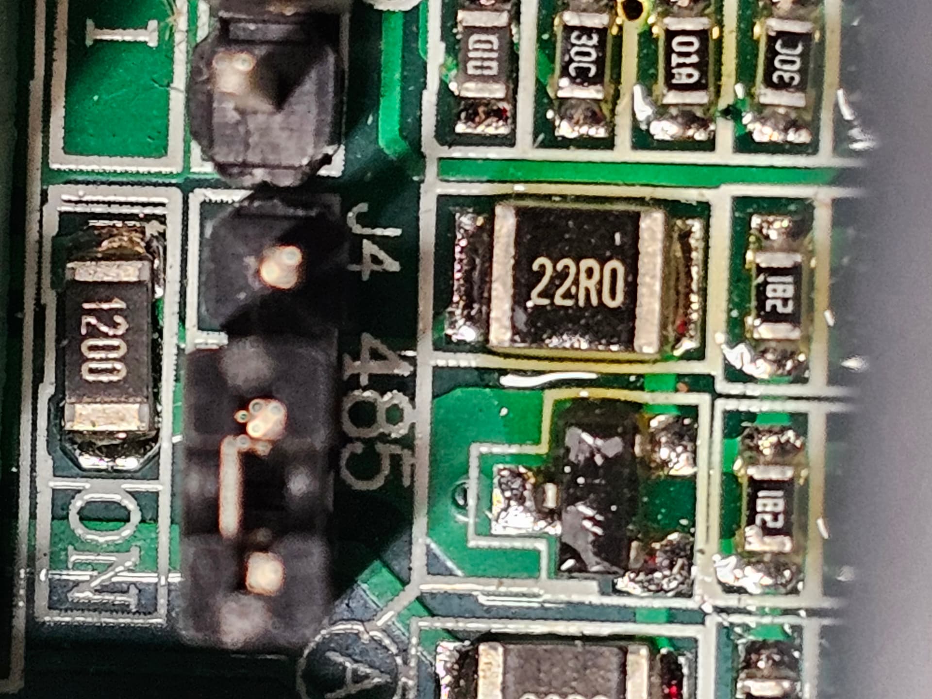
Here is a picture of the jumper just so you know what I am looking at.
It is located right behind the 485 sockets on right side of the board.
The jumper was on the left side originally, I did move it to the right but it just turned the RX LED off.
triple check your wiring (does it work Ok in Manual mode?), please verify this into the vfd programing also:
Register	  Value	     Description
**P00.01**	   2	             Communication running command channel
**P00.03**	   400	     BASE FREQ
**P00.04**	  400	     MAX FREQ
**P00.05**	  100	     MIN FREQ
**P00.11**	    6	            ACELERATION TIME
**P00.12**	    6	            DECELERATION TIME
**P00.13**	  0 o 1	    0 default, 1 INVERSE TURN ( Only Change it if it spins backwards when you turn the spindle on)
**P00.14**	4Khz	0.75-2.2Kw Motor
**P02.01**	1500	SPINDLE POWER ( YOUR CASE: 1.5KW = 1500)
**P02.02**	400Hz	IF YOU CAN CHANGE THE STOCK FREQ. MAKE THIS 400hz from 50Hz
**P02.03**	24,000RPM	MAXIMUN SPINDLE RPM ( IM ASSUMING YOURS IS 24K Rpm too. )
**P02.04**	220	            SPINDLE VOLTAGE/ YOU MUST SELECT 220V manually
**P02.05**	6.818181818	AMPS MAXIMUN for the SPINDLE. ( 1500/220)
**P14.01**	3	Baud rate 9600BPS
**P14.02**	0	N81 o 8N1


also try this
**P00.06**        8           MODBUS communication setting
the bright side is that if we get your vfd to work, we can share the config/programming to Barts team so they help others
You are a very patient man.
I went through all the setting again, we are good. The only question is
P02.05 6.818181818, I input it as 6.8, I might try moving it to the left of the decimal just for giggles.
Right now we still have the TX blinking and RX solid on.
That little test had no effect, putting it back to 6.8
thats a setting to make the vfd only output 1.5Kw at 220V it is 6.8~ amps
as i said earlier: triple check you wiring my man
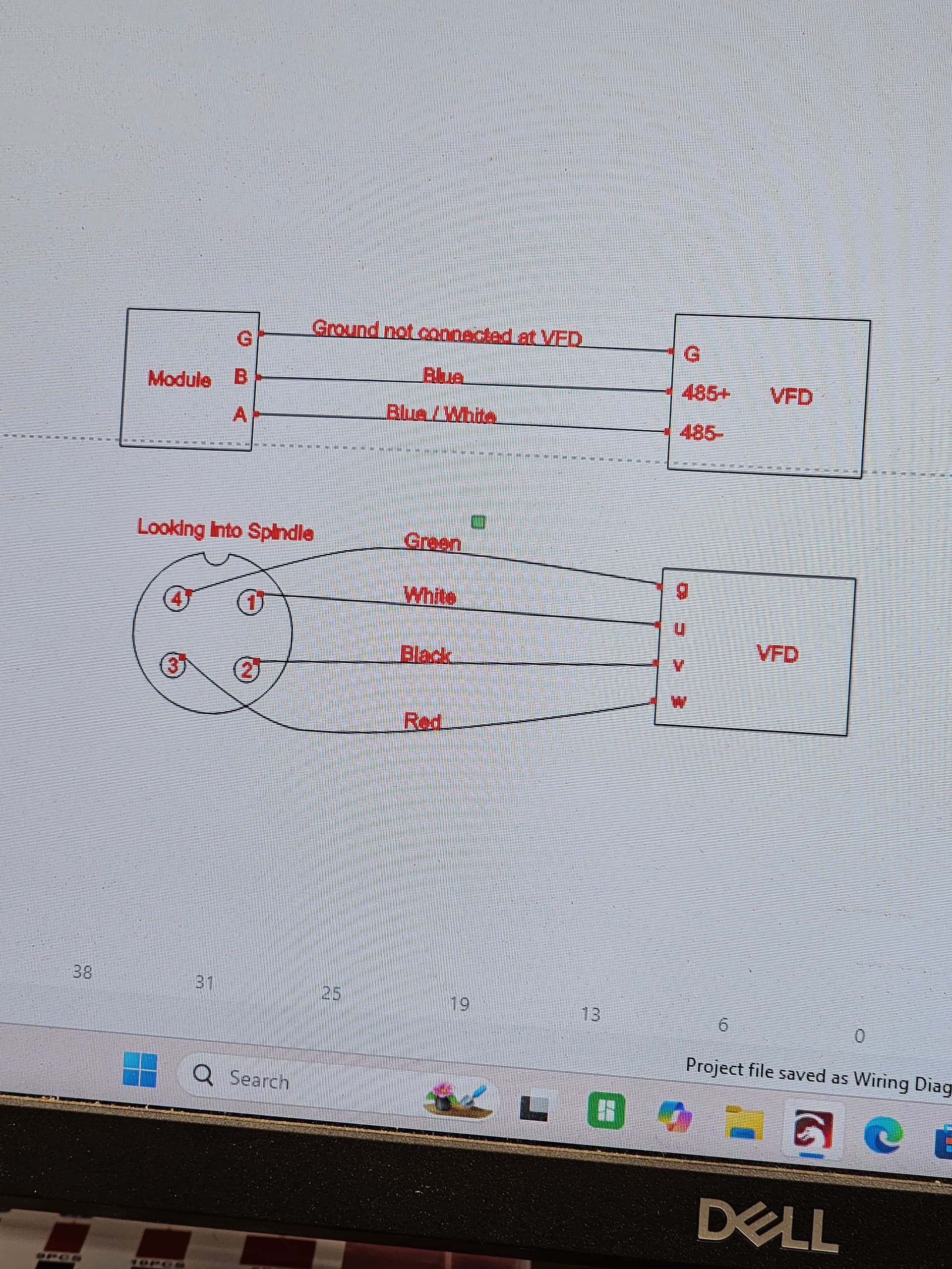
now i would like a diagram ( draw it in Ms paint) and send it to me
want to see how you wired
VFD to SPINDLE and VFD to the isolated module
the wiring is a CAT 6 shielded networking cable with the ends cut off. I used the blue pair, cut the rest flush. Did connect the ground to the chip on the jackpot but did not connect it on the VFD end.
OH boy that is going to be rough, I did the spindle a few months ago. I have it running perfectly by using the keypad on the VFD.
I have removed and rewired both ends of the wires, the blue solid is on the B port, Blue/White is on A and the bare wire is on G at the isolated module
on the VFD solid blue is on 485+, blue/white is on 485-, the ground is not connected.
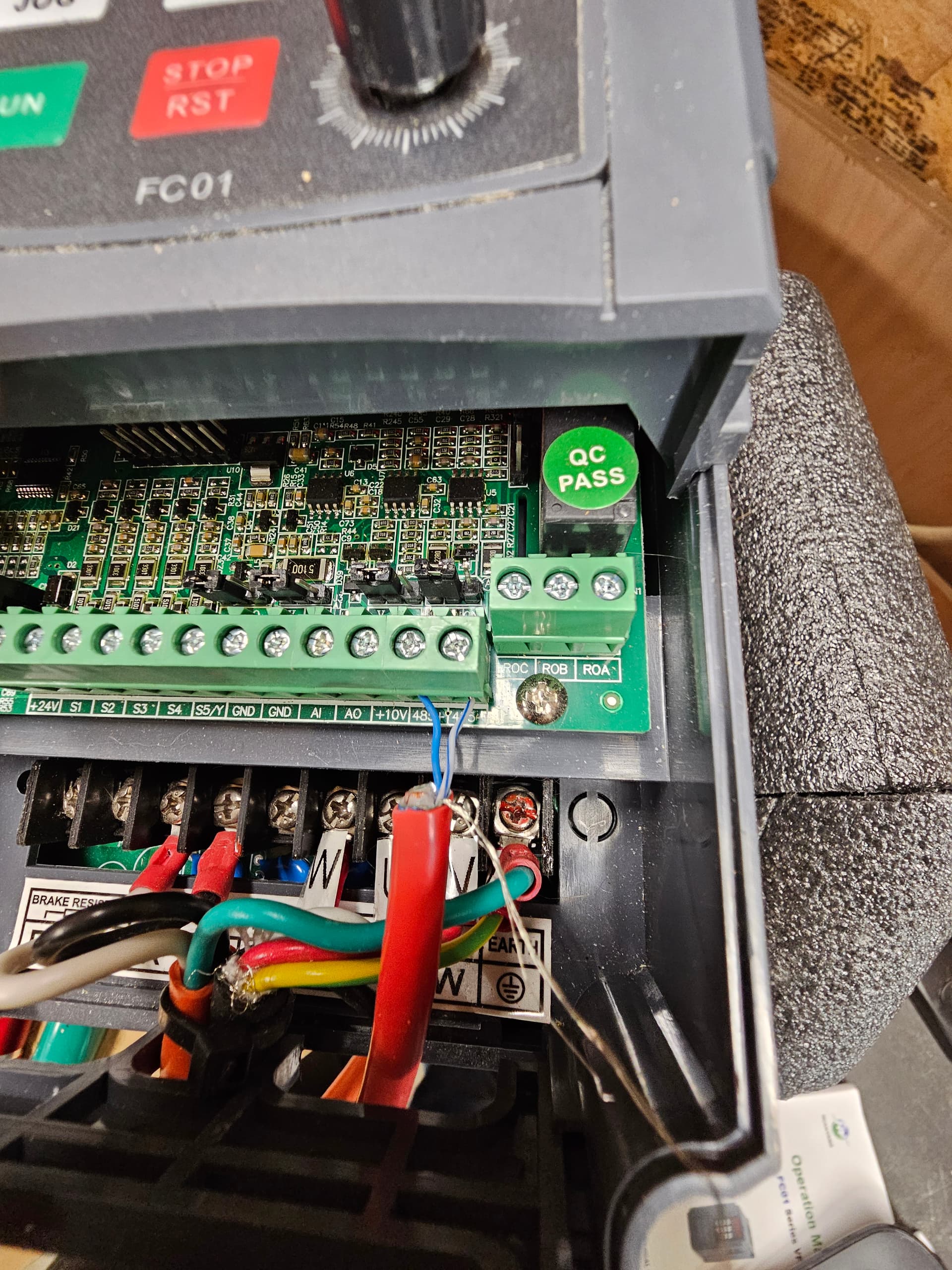
Spindle
I purchased a shielded cable, the U V & W wires are the power, there is a ground wire that is connected to the ground post in the VFD.
I am hesitant to remove the wires from the plug on the spindle, it was an extremely tight fit, large wire cable small hole on plug.
I will send pictures of what I can see clearly.
sorry, as i dont have your exact model i need to see how you wired everything and make a diagram to compare oh how it is supposed to work. my spindle its a 1.5kw 110v motor with the HY model vfd (bought the same model its linked on the fluidnc wiki
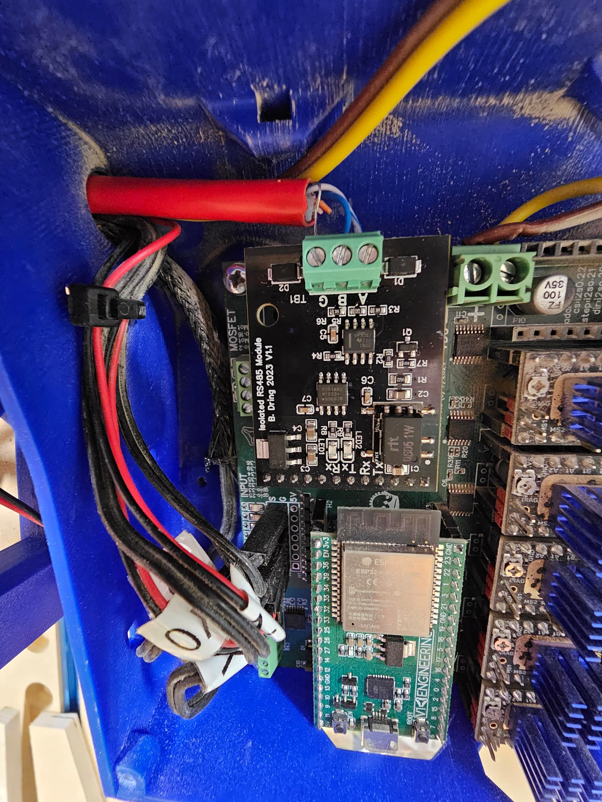
if you reverse the A/B connection in the Module?
what happens?
the TX continues to blink, the RX is not lit.
The only thing I haven’t done is connect the ground at the VFD. According to all I have read that is not advised.
as you have the wiring The solid Blue Should be the A connection in the MODULE
the White/Blue should be B.
please reset the parameters and try the last edit i wrote THIS:
Register	  Value	     Description
**P00.01**	   2	             Communication running command channel
**P00.03**	   400	     BASE FREQ
**P00.04**	  400	     MAX FREQ
**P00.05**	  100	     MIN FREQ
**P00.11**	    6	            ACELERATION TIME
**P00.12**	    6	            DECELERATION TIME
**P00.13**	  0 o 1	    0 default, 1 INVERSE TURN ( Only Change it if it spins backwards when you turn the spindle on)
**P00.14**	4Khz	0.75-2.2Kw Motor
**P02.01**	1500	SPINDLE POWER ( YOUR CASE: 1.5KW = 1500)
**P02.02**	400Hz	IF YOU CAN CHANGE THE STOCK FREQ. MAKE THIS 400hz from 50Hz
**P02.03**	24,000RPM	MAXIMUN SPINDLE RPM ( IM ASSUMING YOURS IS 24K Rpm too. )
**P02.04**	220	            SPINDLE VOLTAGE/ YOU MUST SELECT 220V manually
**P02.05**	6.8	AMPS MAXIMUN for the SPINDLE. ( 1500/220)
**P14.01**	3	Baud rate 9600BPS
**P14.02**	0	N81 o 8N1


also try this
**P00.06**        8           MODBUS communication setting
FROM PAGE 88 on your VFD manual:
When you operate on the VFD with the table above, it is necessary to enable some parameters. For
example, the operation of running and stopping, it is necessary to set P00.01 to communication running
command channel and set P00.02 to MODBUS communication channel. And when operate on “PID
reference”, it is necessary to set P09.00 to “MODBUS communication setting