HOWTO - A "simple" gift box

I decided to make a small gift box, mainly as an exercise in modeling and 3D machining
I learned quite a lot concerning the design process, and wanted to share a kind of tutorial

This little project is a cool practical gift, and will cover a lot of “not so basic” modeling and machining techniques
I hope this long post will give you an incentive for your future projects, and maybe help you learn new tricks along the way :slight_smile:

F3D file included for anyone willing to help :slight_smile:
View: Fusion
Download: Deleted,

Design Part 1: A little box with a refined lid

The box is a simple 100mm diameter cylinder with a cavity inside

First, draw the sketch with outer dimension, and two offset circles: one for the inner wall at -5mm, one for the “lip” we’ll add later on at -3.35mm (more on this strange value later)

Then, extrude a cylinder from the sketch, and make another cut extrusion for the inside cavity

The box has a non-planar split between the box and lid

You will need to construct a “tangent plane” to the boxe’s side to draw the shape of this split

Create a sketch on this plane and draw a spline
Be careful that the spline stays under the cavity’s top, and doesn’t clip through the bottom
You don’t need the spline to cover the whole width of the cylinder, this choice is up to you, experiment and have fun…

Use the “Split body” tool to separate the bod from the lid

Adding contrasting appearences to the two bodies helps visualizing what you’re doing a lot

Form the lip on the “box” part by selecting the outer circle from the first sketch and cutting through
The “magic” of keeping the curve relies on selecting “Start: Object” and selecting the lid’s outer underside face

Next we need to mirror the shape on the lid
Select the outer ring from the sketch once again, extrude down using “Start: Object” , again selecting the lid’s curved underside face, and using the same distance as the previous operation
Hide the box part to avoid joining with it

Now we have two matching parts with matching lip
But want the inner wall of the box to go all the way up to the lid, without a curved edge

We need to flatten this lip in the lid

Select the inner ring from the first sketch, and cut all the way up to the lid’s underside
Hide the box part to avoid cutting it

Next, do the matching operation on the box part

Select the same inner ring again, and extrude up to the lid’s underside, but this time, we use Join (note: hide the cap after selecting it so that it doesn’t all join in a single body)
Use an offset so that the newly created wall doesn,t touch the lid, this will help closing the box…

This is part 1 done!
We now have a nice little box with a non planar cut and lip, that’s already pretty cool :slight_smile:

But we can do better :wink:

4 Likes

Design Part 2: Carved top

In this part, we’ll add a relief to the top of the lid, starting from an image used as a heightmap

We’re looking for an image in greyscale, with smooth lines and variations in color
I took this image from a google search, but you can try generating similar ones with dall-e/midjourney if you want

Note: In order to ensure smooth transitions in height, open the image in your favorite editor, convert it to greyscale, and apply some blur

You will need to install this plugin to convert the image to a surface une Fusion360

Once installed, run the plugin and adjust the settings

I mainly use the "Pixels to skip settings to adjust the scale and ensure the surface is large enough to cover the lid entirely, but you can also scale it later on
The other important setting here is “Max height”, so that the generated surface stays within the lid top’s thickness

Once you’re happy with the result, click generate

Click the “Create Form” button

This will switch to a new workspaces with new menus, where you can select the “Convert” tool

Choose “Quad mesh to T-spline” and select your surface, validate, and wait… this can take quite a bit
image

Once done, click “Finish form” to exit the form workspace

You have two objects now;
The first one is the mesh generated from your image (we won’t need this one anymore)
The second one is the “t-spline form” we just created, that’s the one we’re working with now…

image

Move and scale the form so that it fits inside the lid’s thickness, and covers it entirely, and until you’re satisfied with the placement of the pattern
Making the lid slightly transparent helps with visualizing the result

Select the “Replace face” tool, select the lid first as “source”, and the t-spline form as “target”

Click ok and hide the form to see the result

You can add a roundover, chamfer or anything if you want

And that’s the design completed, this little gift box is getting pretty fancy now :slight_smile:

This was the “easy” part though, because machining this box will require quite a lot of more advanced operations and techniques…

3 Likes

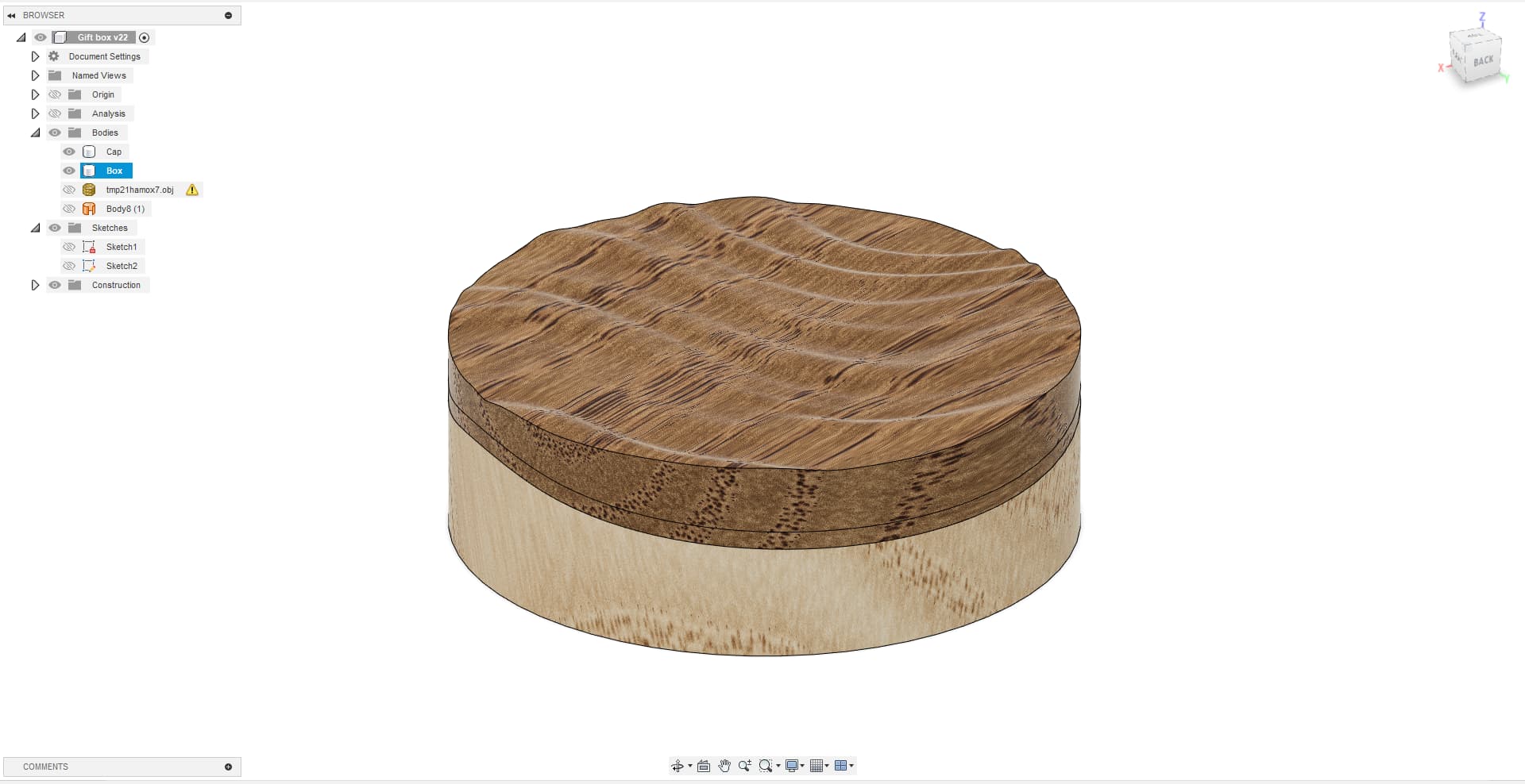
CAM: Preparing to machine

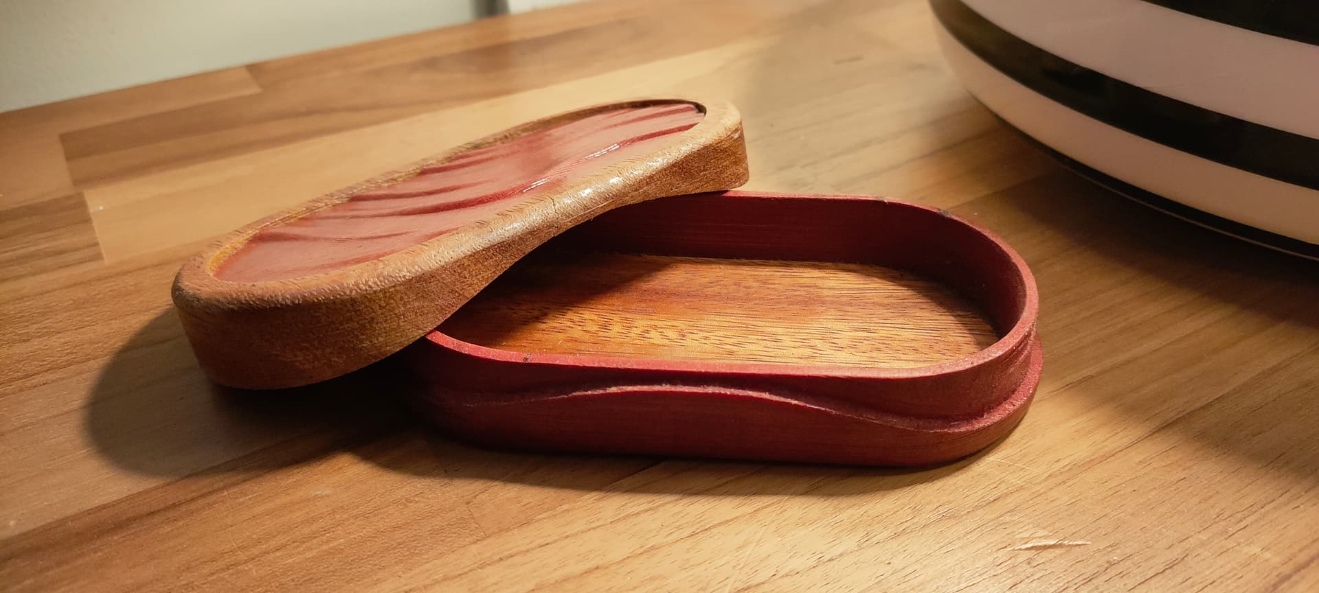
This is the fun part…
In order to machine this fancy little box, we will need to use 2 or 3 different tools, and machine a piece from both sides

Each operation or “setup” will generate a different gcode file, that you will need to execute in the correct order, with manipulations and tool changes in between them
Keeping your machine’s position between these operations is critical, so you might want to check that your endstops are correctly setup before continuing…

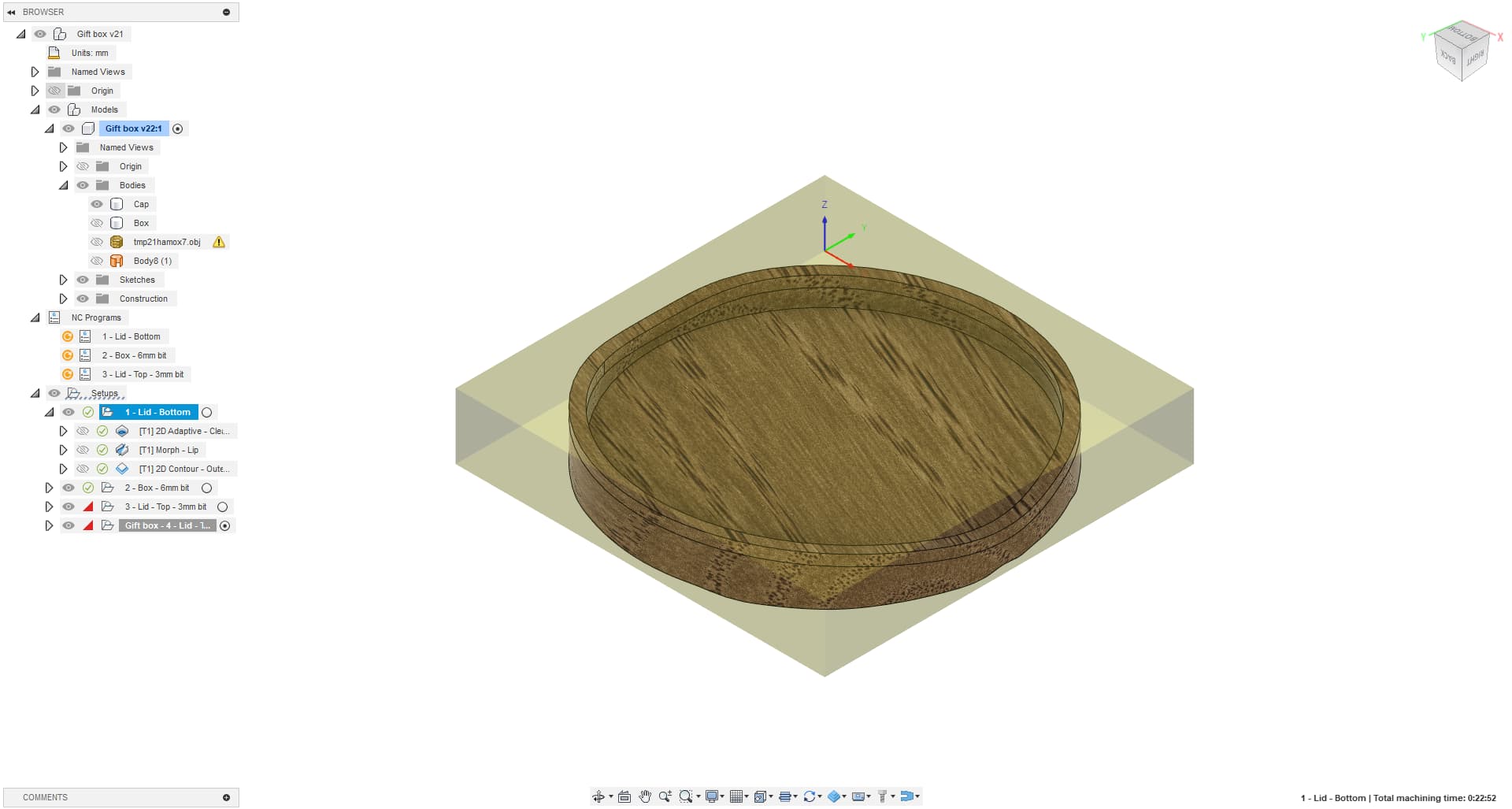
First setup: Cutting the lid from the underside

For this setup I’ll use a 6mm in diameter, 24mm long, 2 flutes downcut bit to cut down on machining time and get a better finish
Alternatively you can use any 1/4" straight bit you have, this will save you a tool change later…

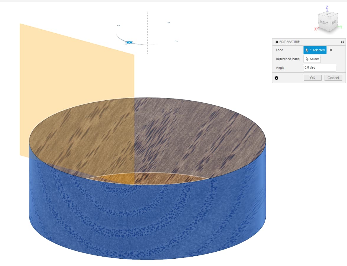
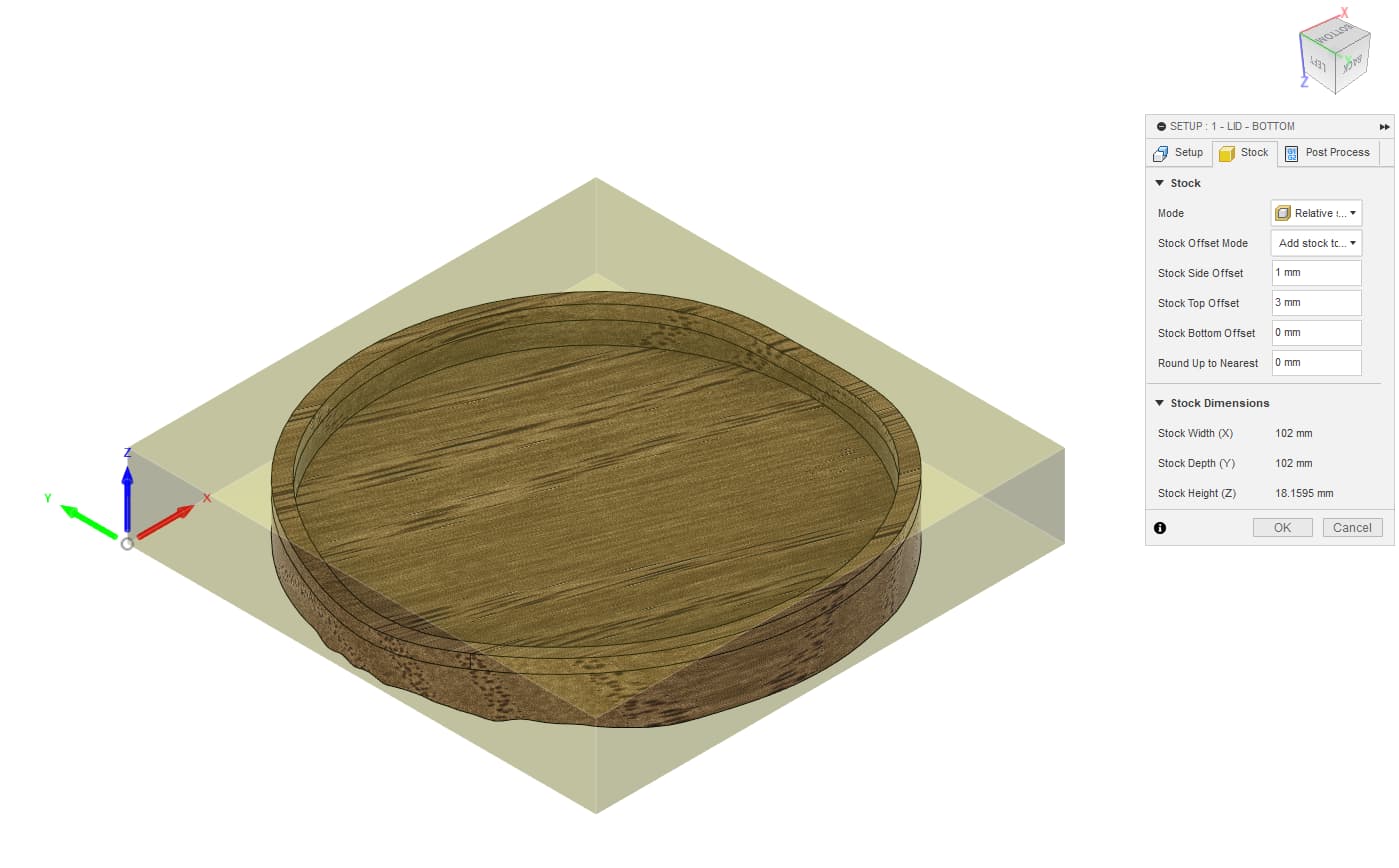
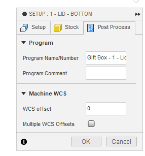
Create the setup, select the lid model, and adjust stock and origin according to your situation/preferences

I set up the Z origin at bed level, so that I can guarantee the top’s thickness whatever the stock thickness.
This is an essential part of the setup, as we will need to reference known height later on…

Note: My stock is 18mm-ish thick so I add an offset to the top accordingly

You can directly name the generated gcode file here too, which will help you staying on track later on…
image

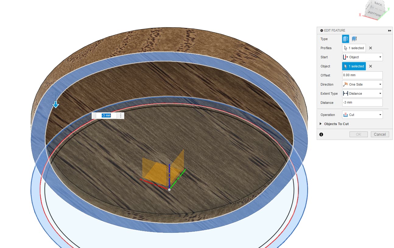
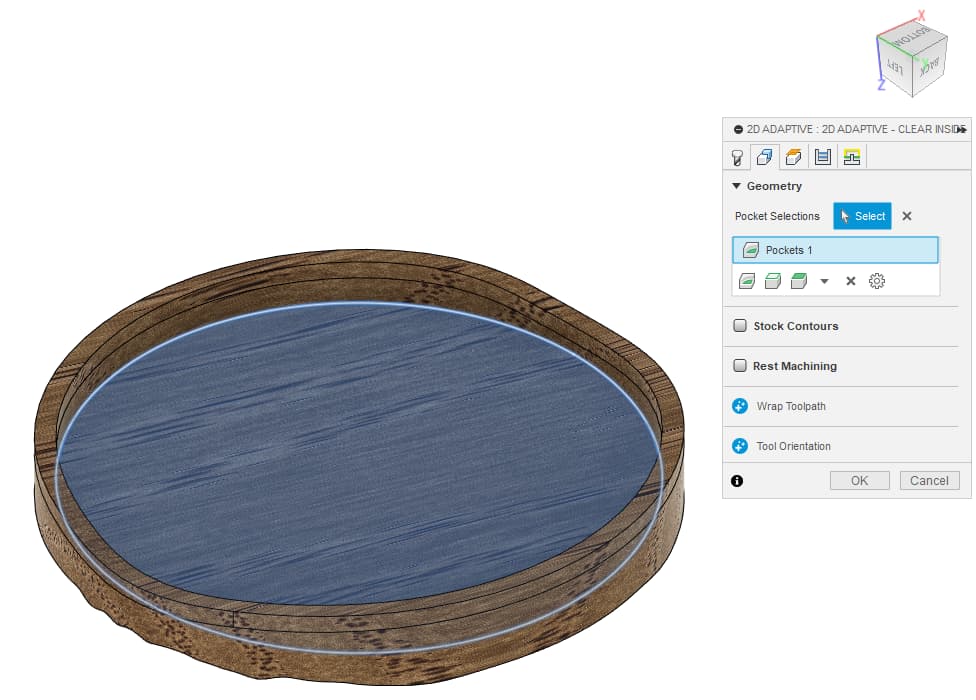
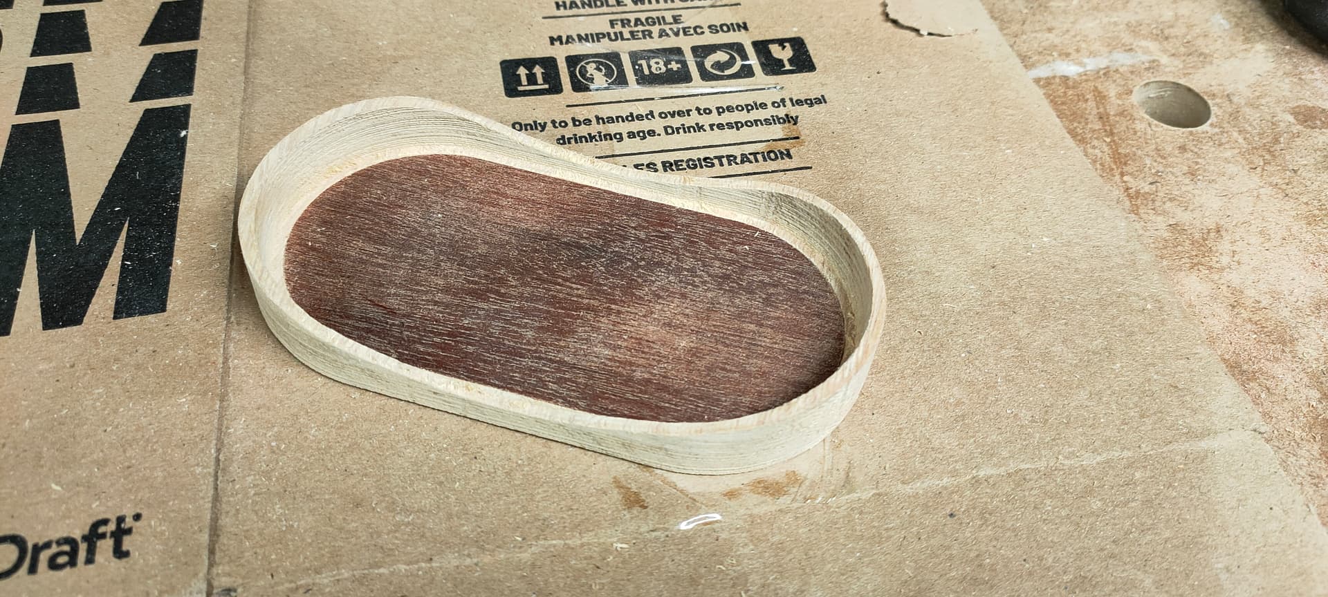
First operation is a 2D Adaptative clean of the inside pocket, nothing really complicated, adjust setting according to your machine , bit, and taste…

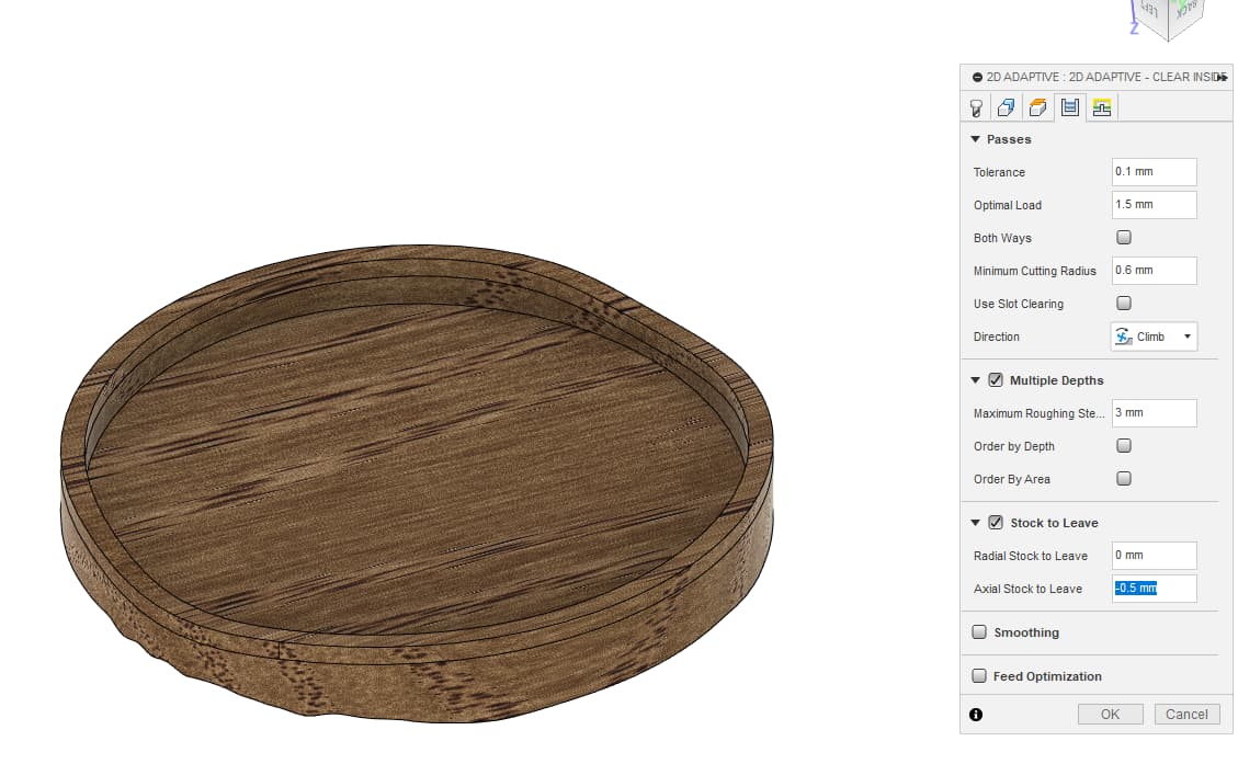
The only setting of note here is “Stock to leave”
I use a negative radial offset here in order to “widen” the pocket and get the lid to fit
This is just a first approximation, we will get the correct fit when machining the other part later on so don’t worry too much about this


Note: The exact value may change on your setup, mine is relatively high because this specific bit has a few calibration problems I didn’t solve yet… A typical value would be “-0.20mm”

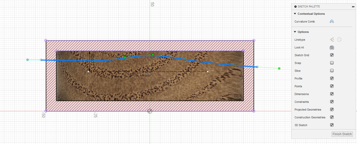
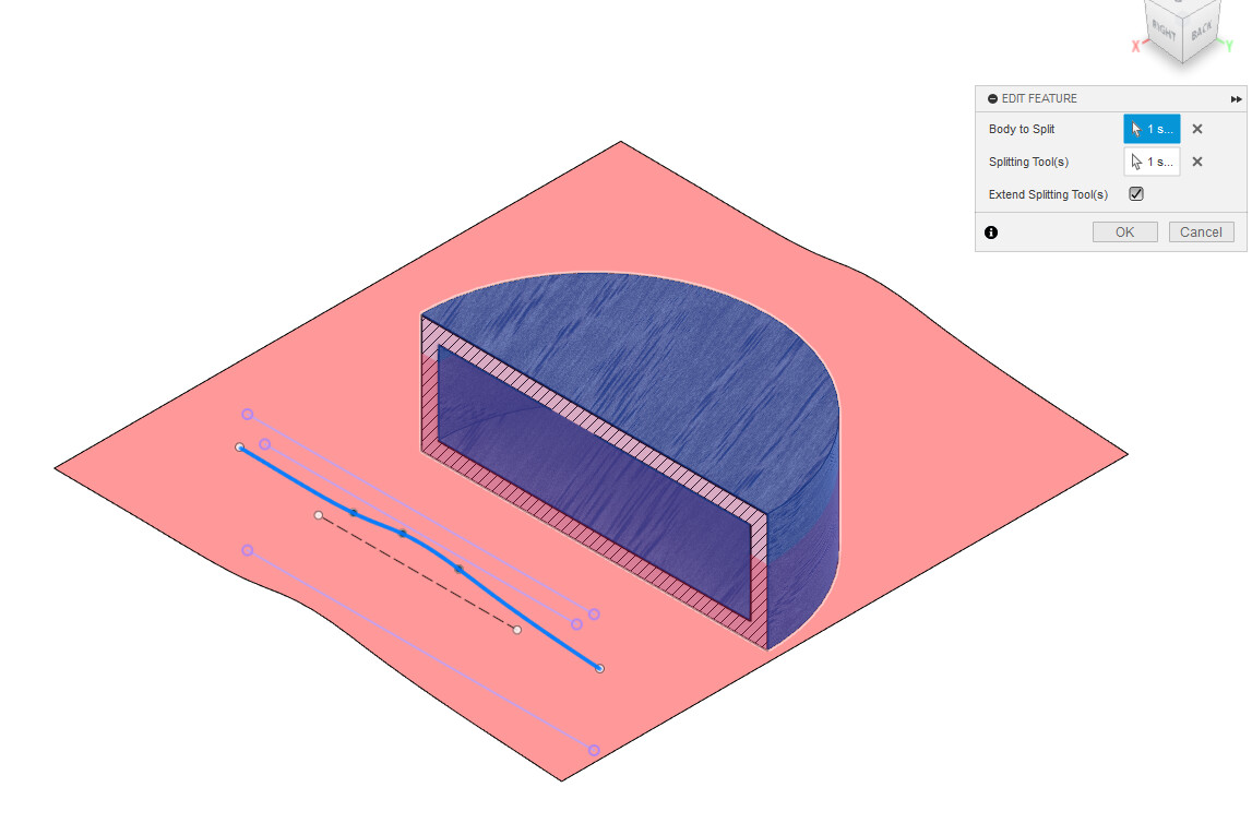
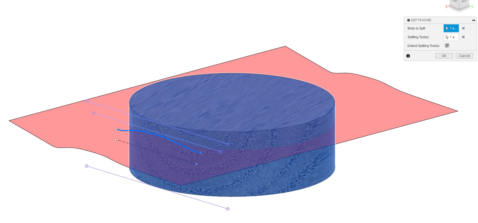
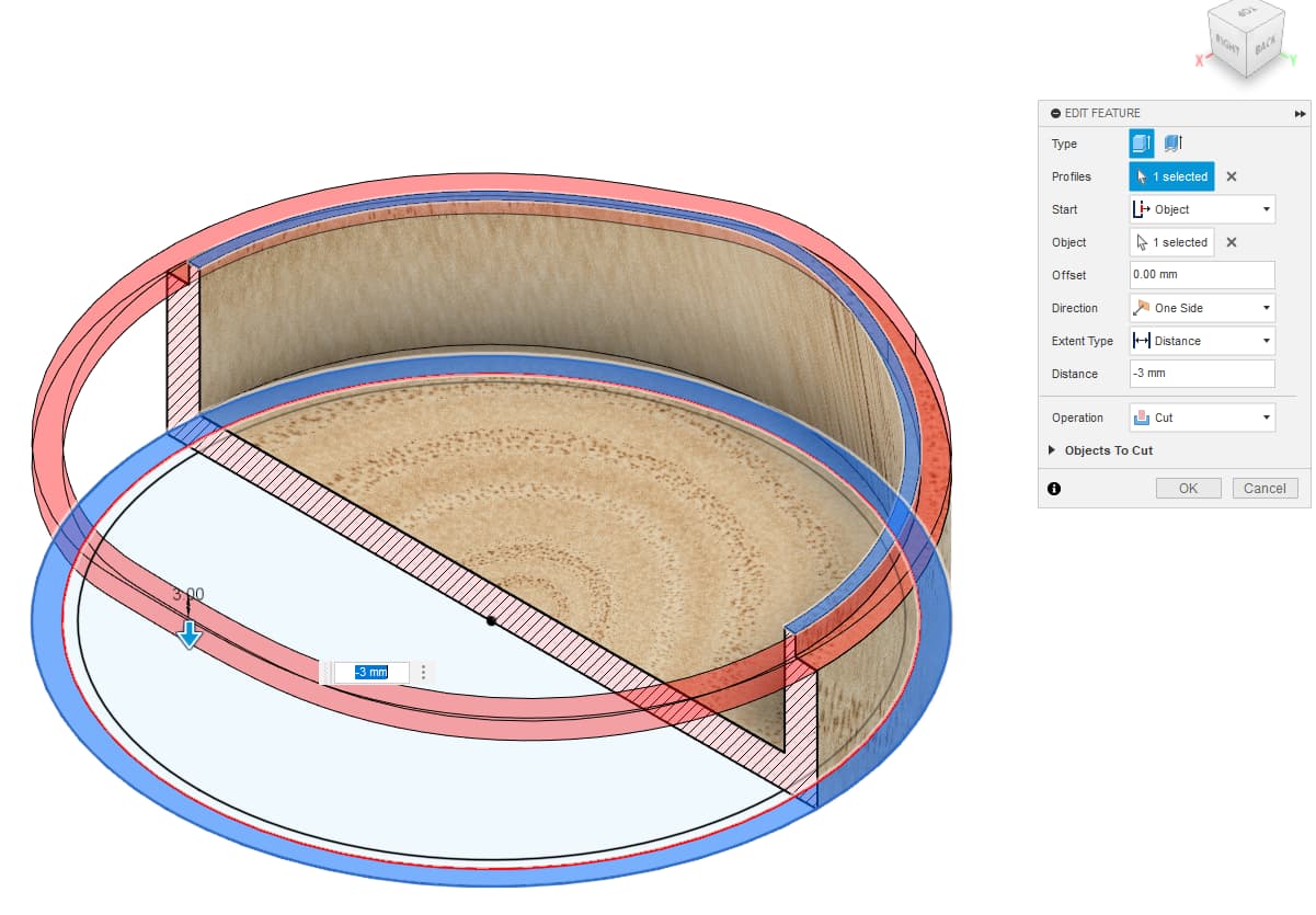
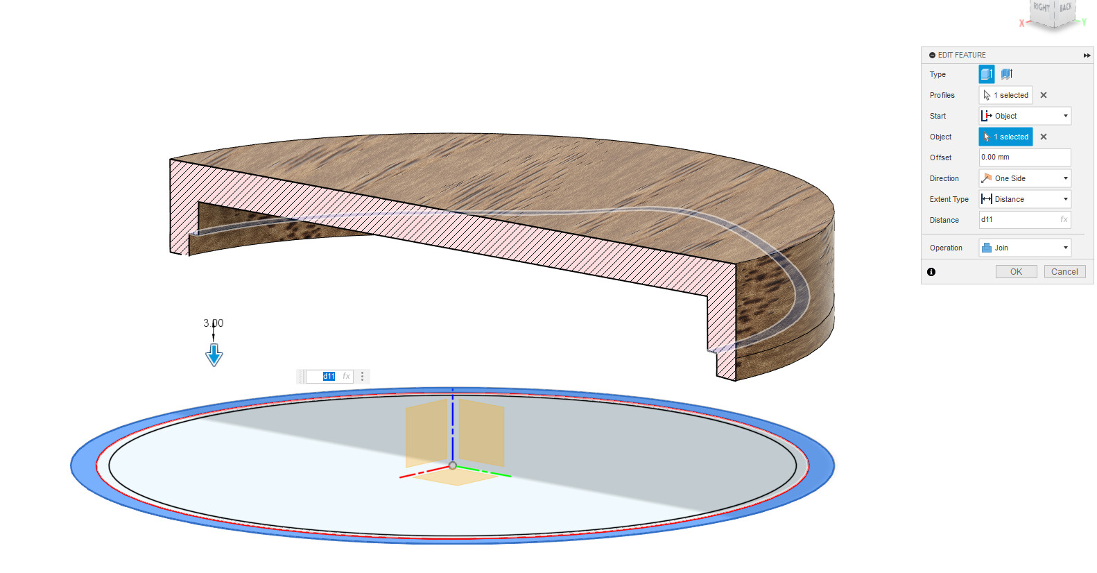
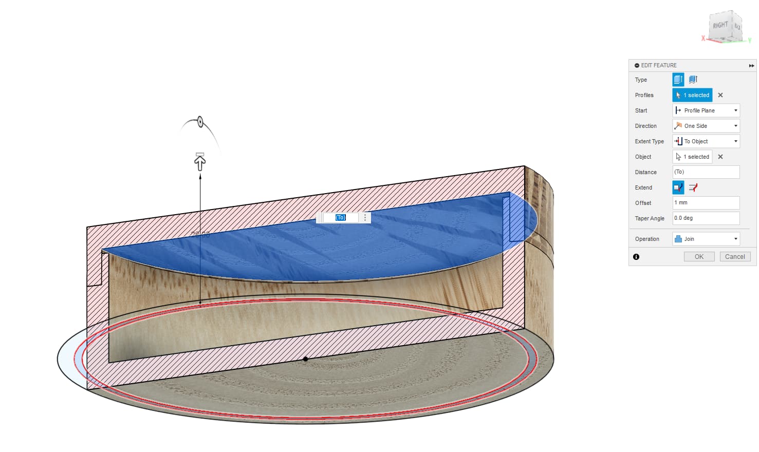
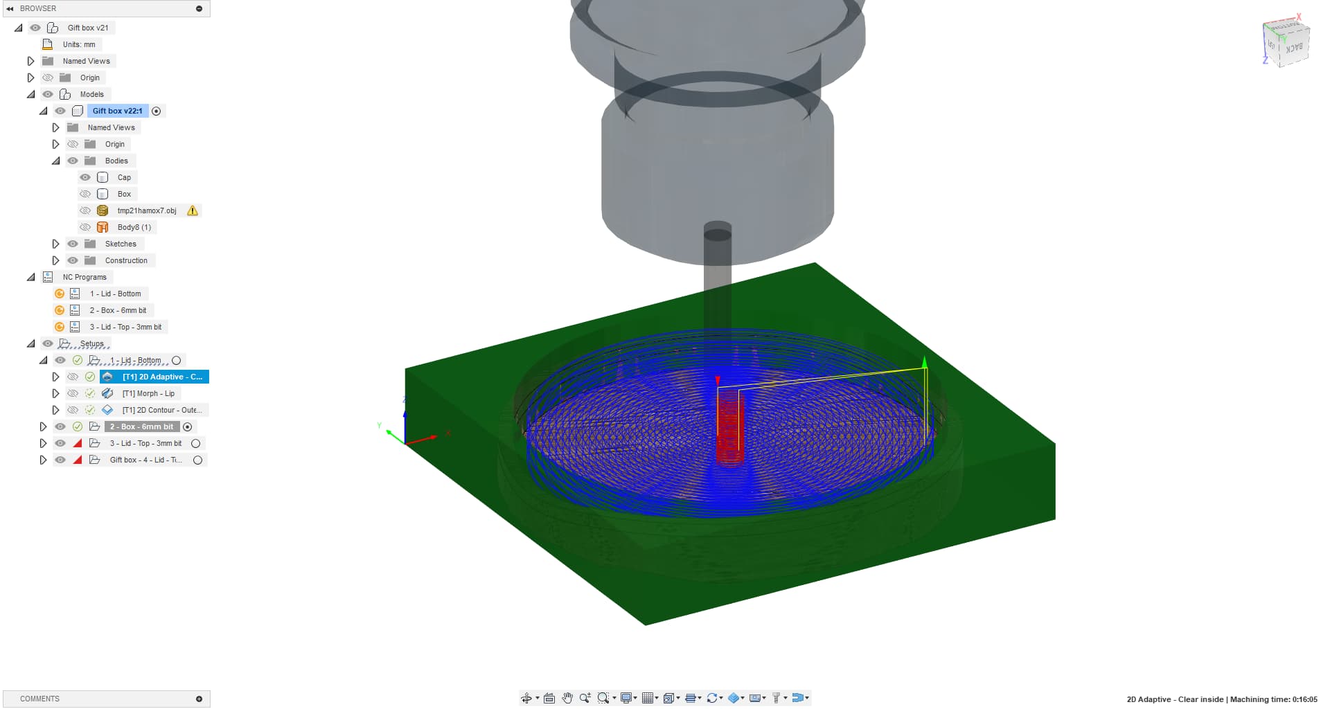
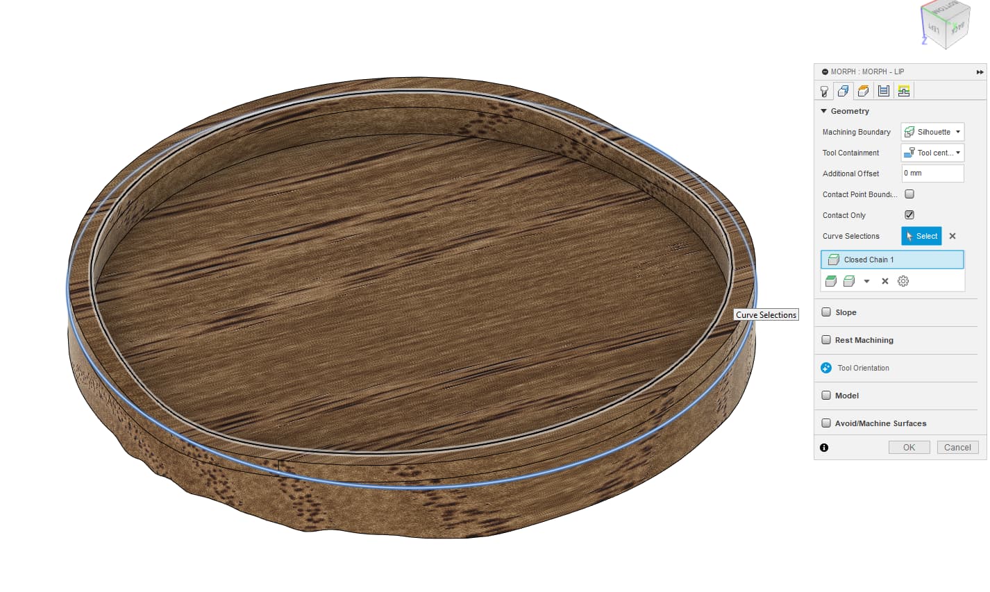
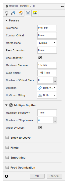
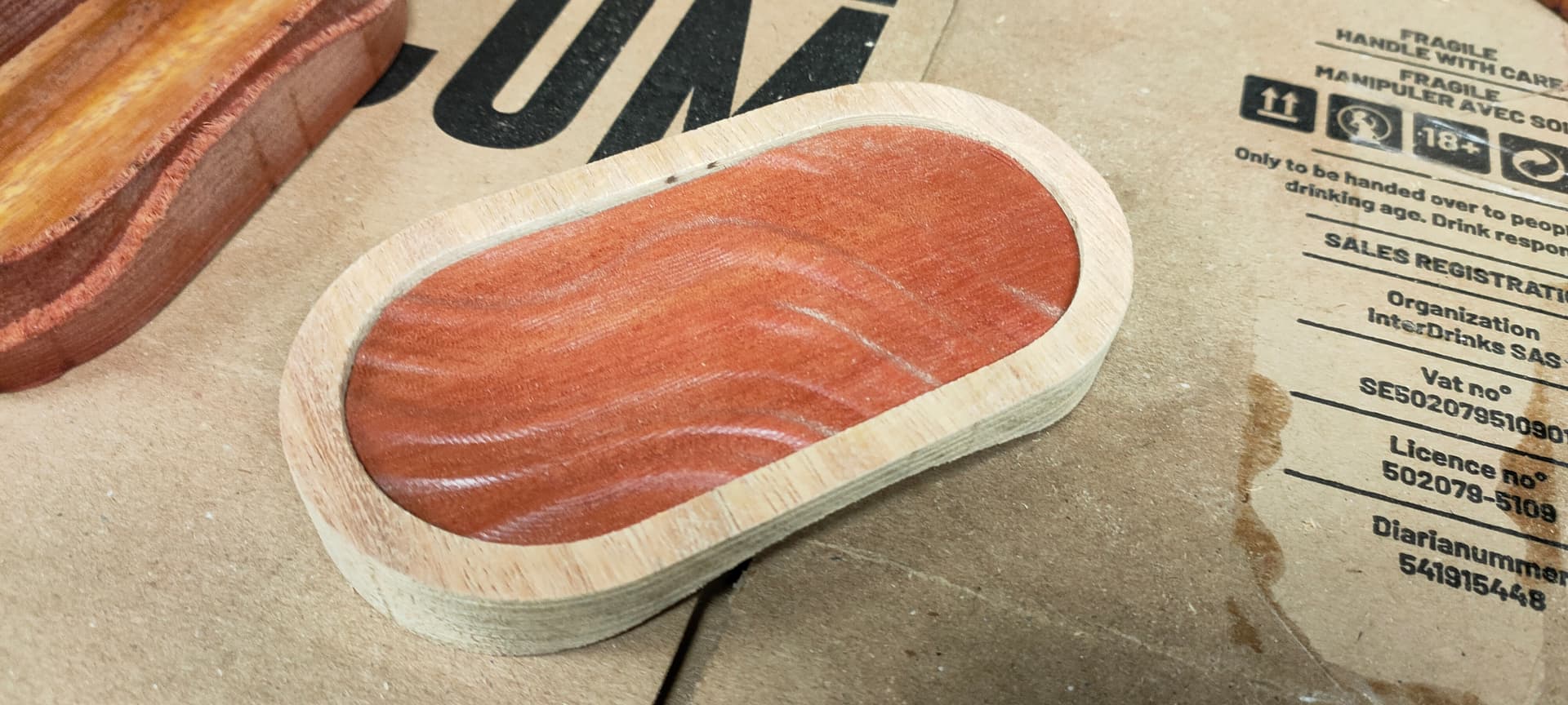
Second operation is a “Morph”, and it’s a 3D operation you may have not used yet
image

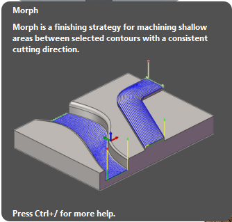
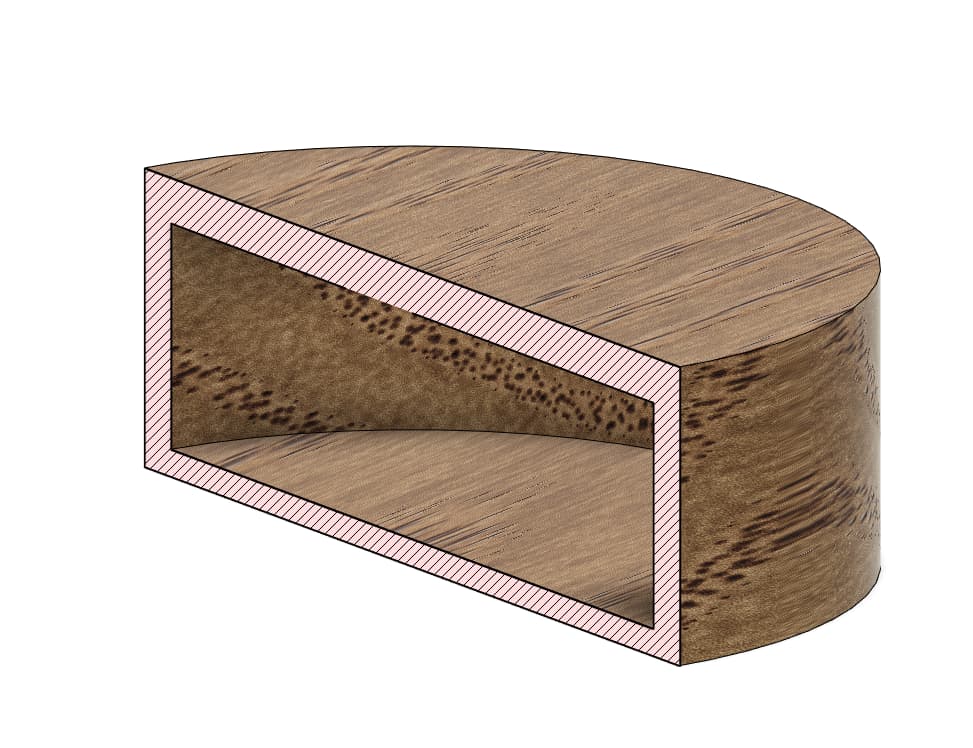
This operation will follow a continous 3D path between two lines, which is exactly what we need to form the curved lip under the lid
So we select thos 2 contours, and apply…

Just pay attention to the DOC, you may want to activate the “Multiple depth option” to avoid a crash

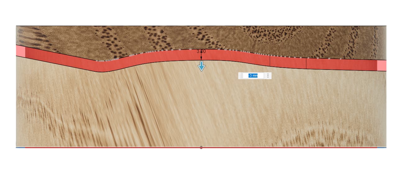
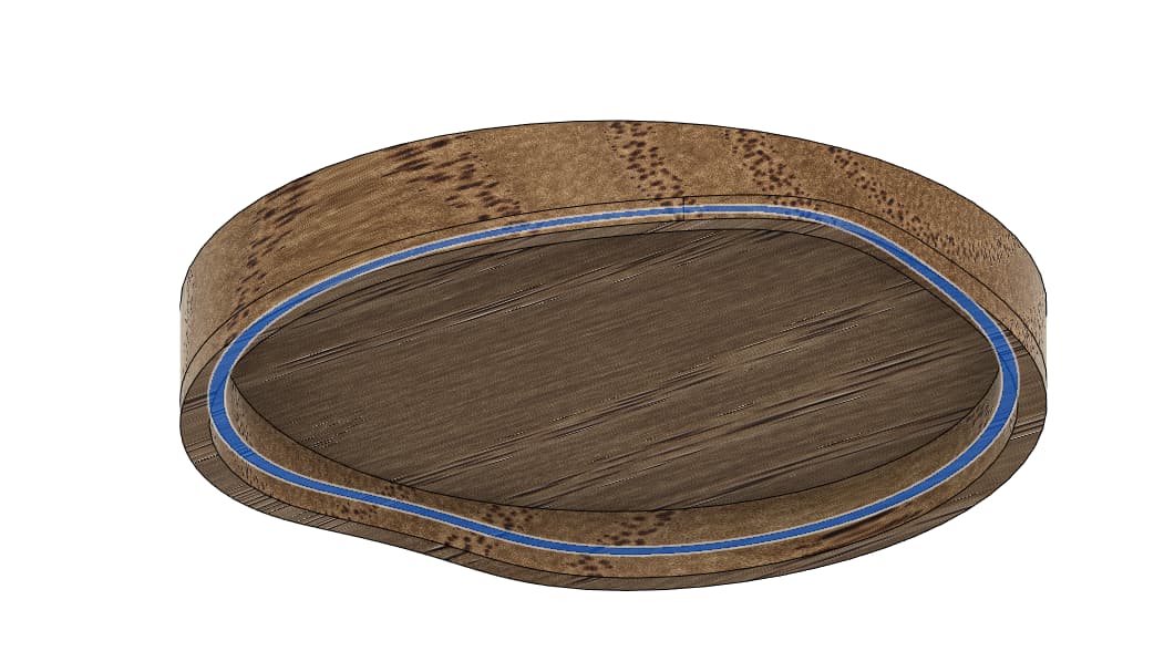
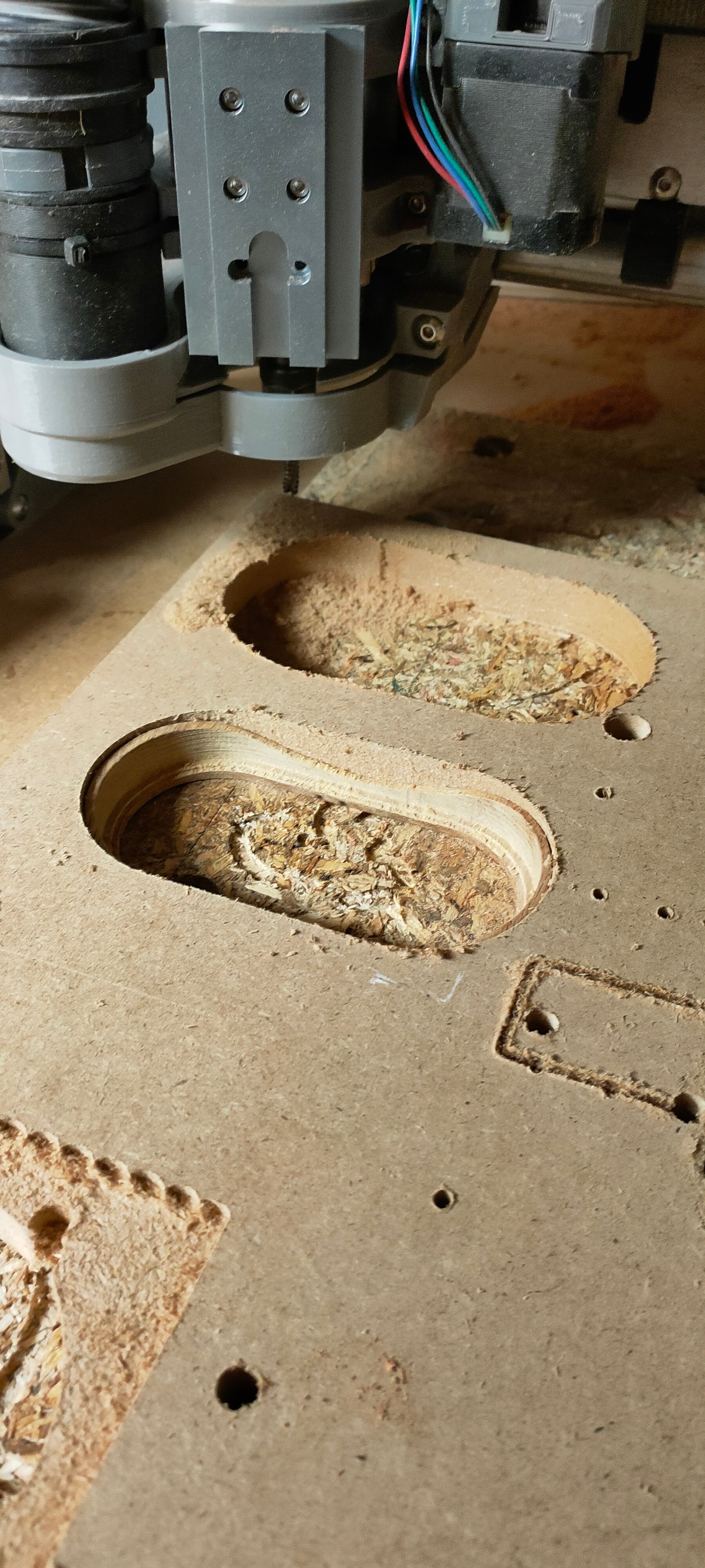
Here’s the resulting toolpath

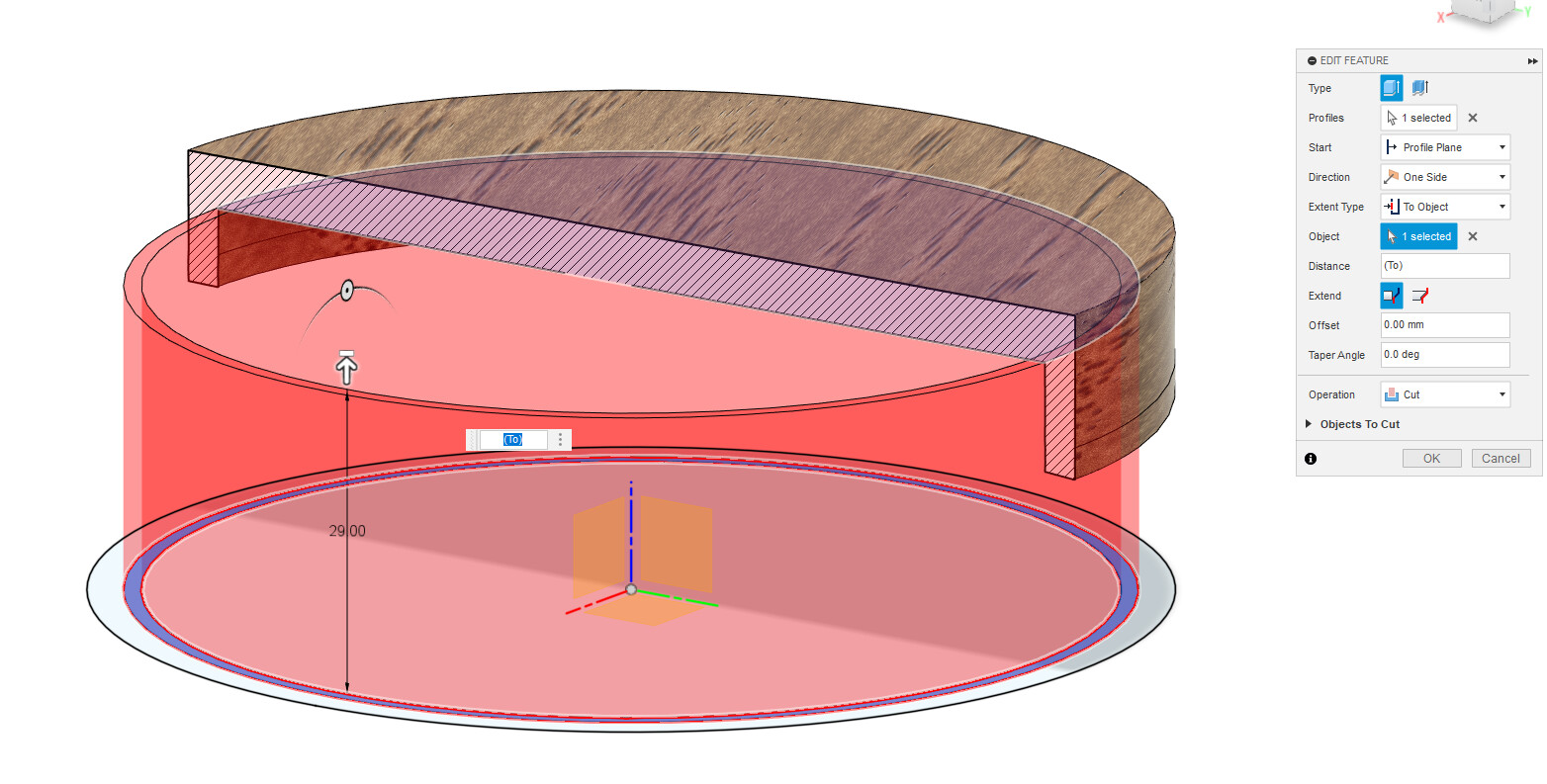
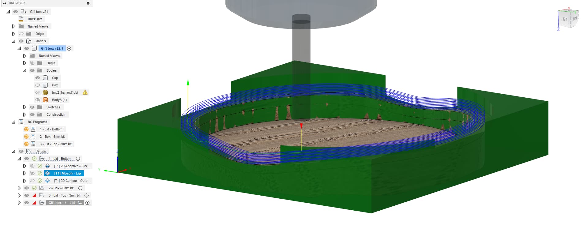
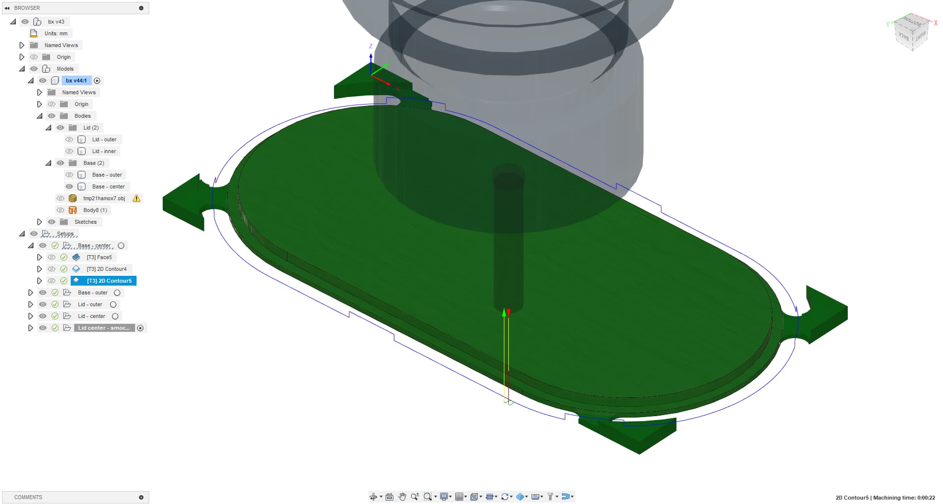
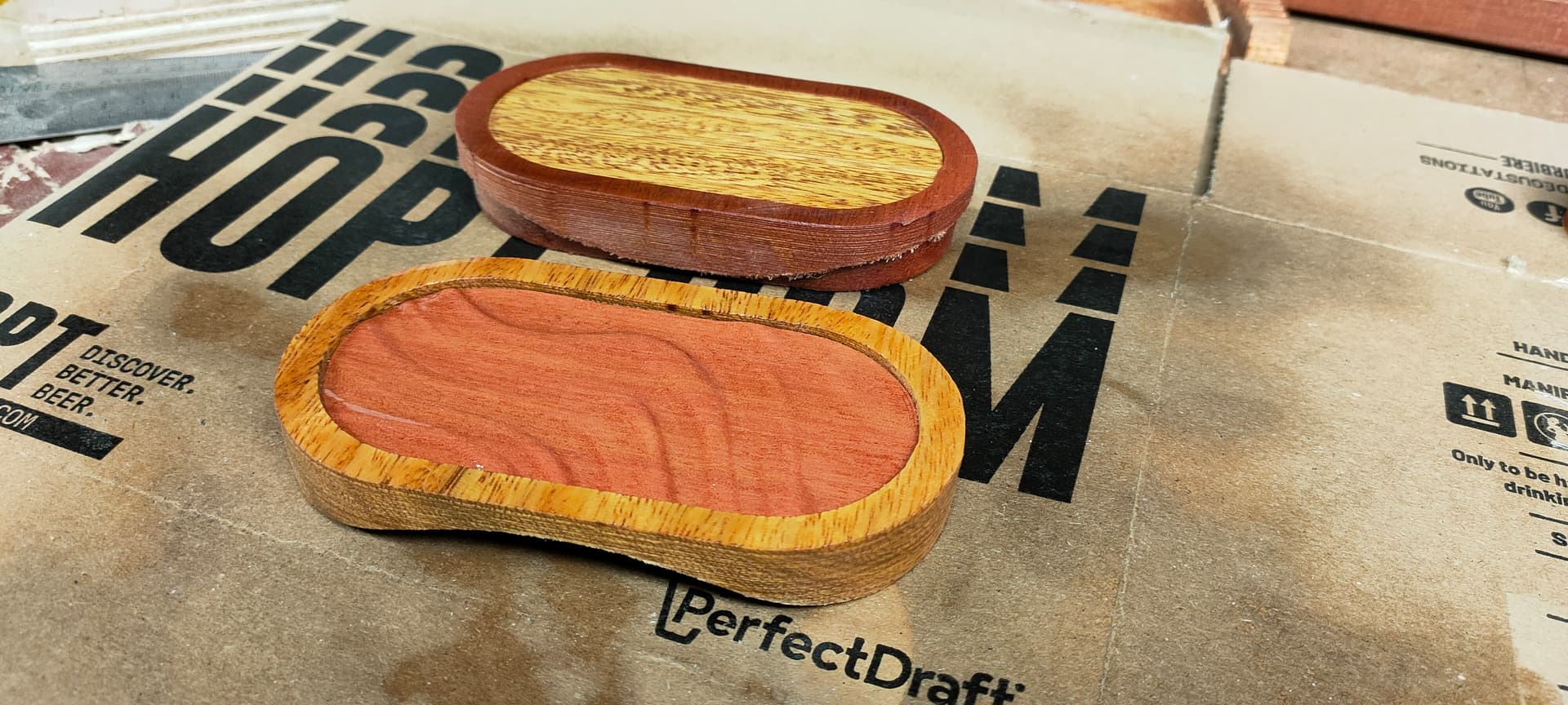
The third operation is a simple 3D contour to cut-out the part.
You may choose to use tabs or not according to your habits and setup, it doesn’t matter for this setup

Note: we’re not done with the lid just yet, we need to carve the lid’s top on the other side, but we’re not doing this just yet…

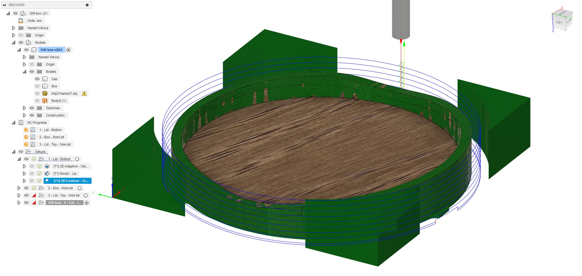
Second setup: Machining the boxe’s body

Create a new setup, reference the bed as Z origin, adjust stock offsets, you know the drill…
Same as previous setup, I use a 6mm bit, you can use any other bit you like

Important note: Be aware that, depending on the bit size and lip shape you have, you may not be able to machine the lip properly. If this is the case, switch a thinner bit, or adjust the spline shape in design and try again.

First operation is a “Surface facing” of the top of the box inner wall
Pretty simple and quick operation, it just ensures a straight fit and known final height

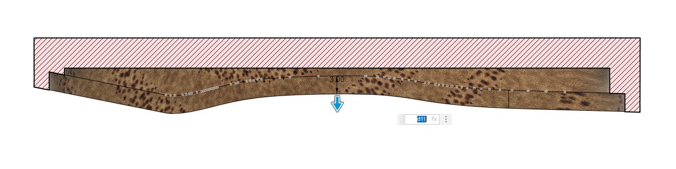
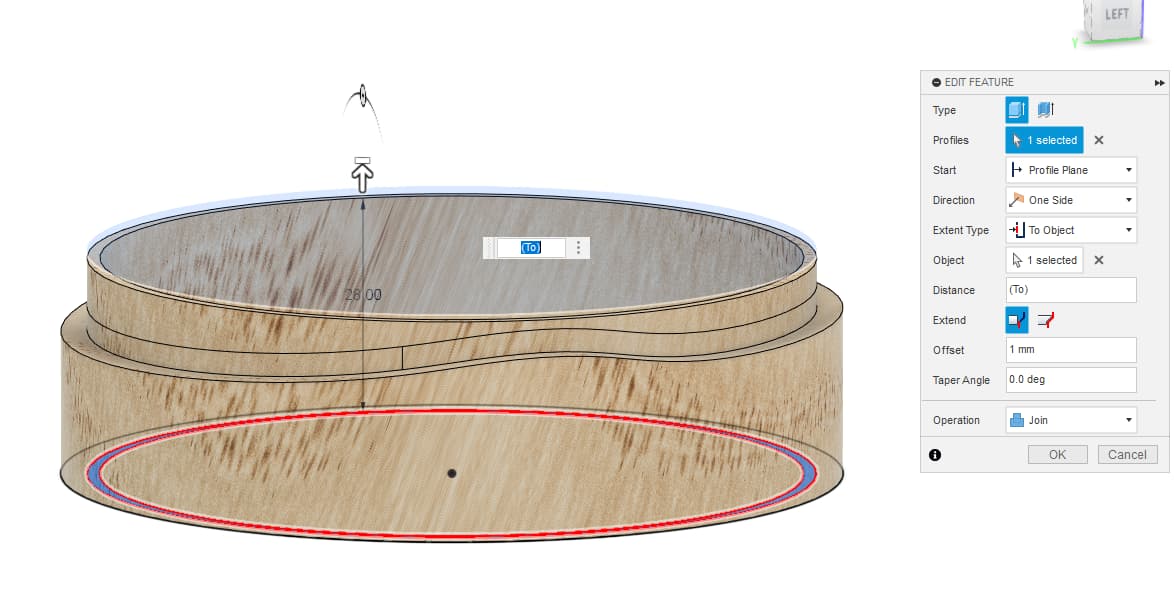
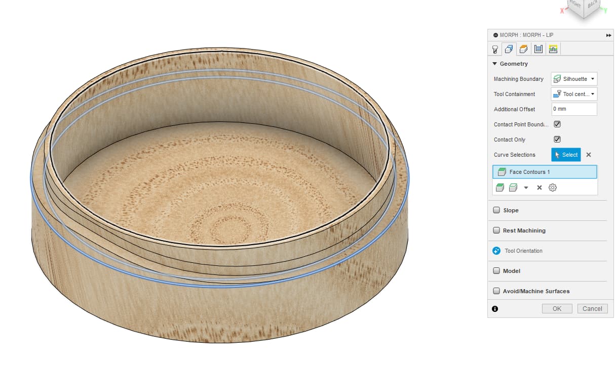
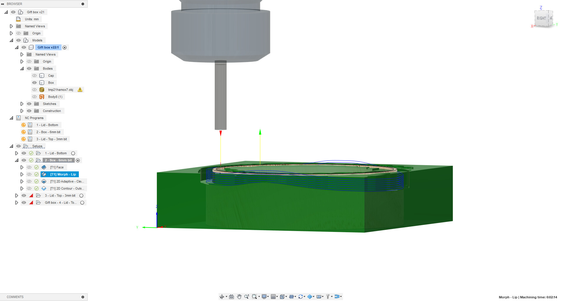
Second operation is a “Morph” of the lip

It pretty much works like the first one, but I had a pretty hard time making this work though…
From my understanding, if the with between the two contours of the morph operation is too narrow, it will just be ignored…
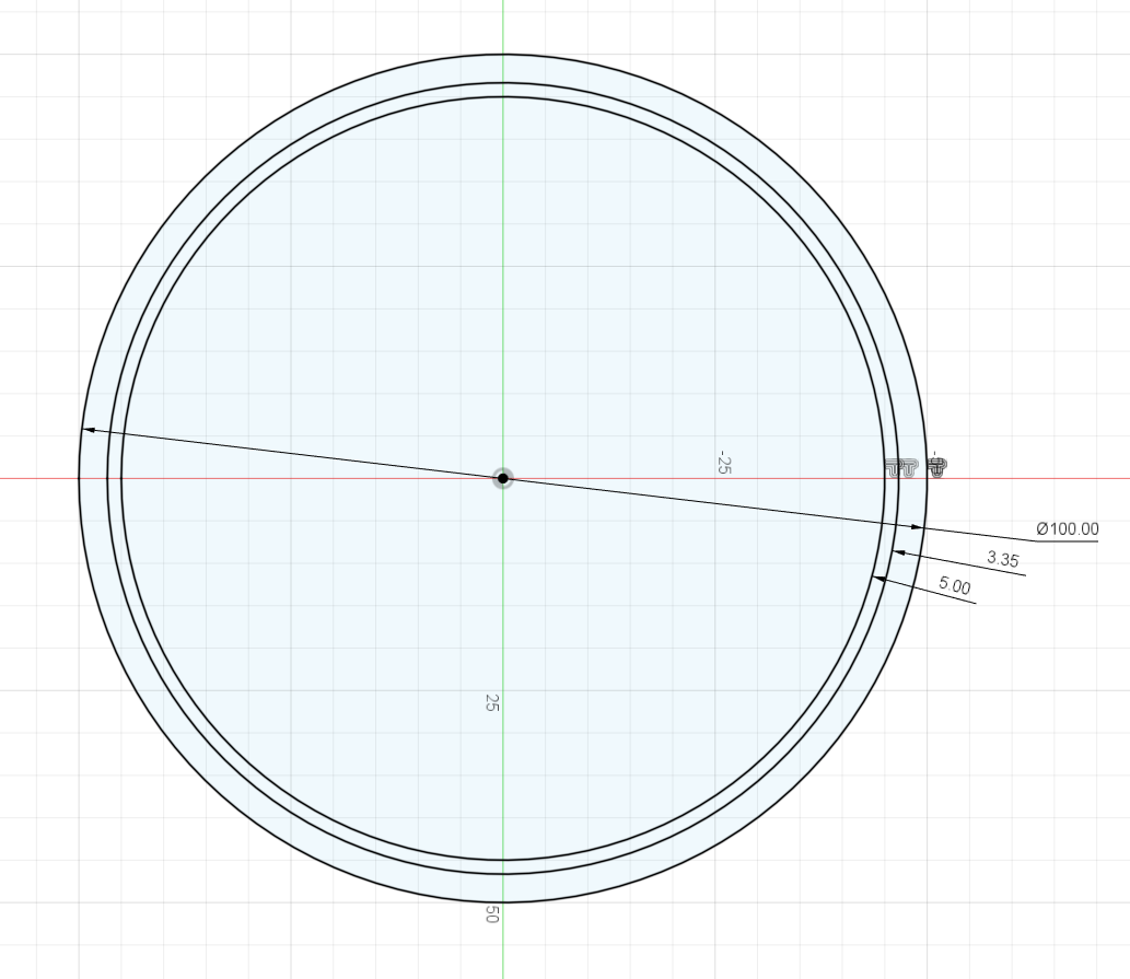
I solved this problem by widening the lip to more than half the diameter of the bit (hence the 3.2mm offset at the very begining of design…) this seems to do the trick…
If anyone knows a better way, I’m all ears :slight_smile:

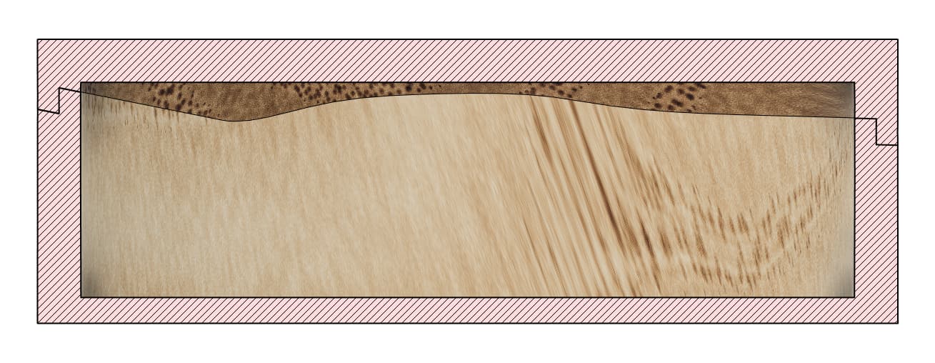
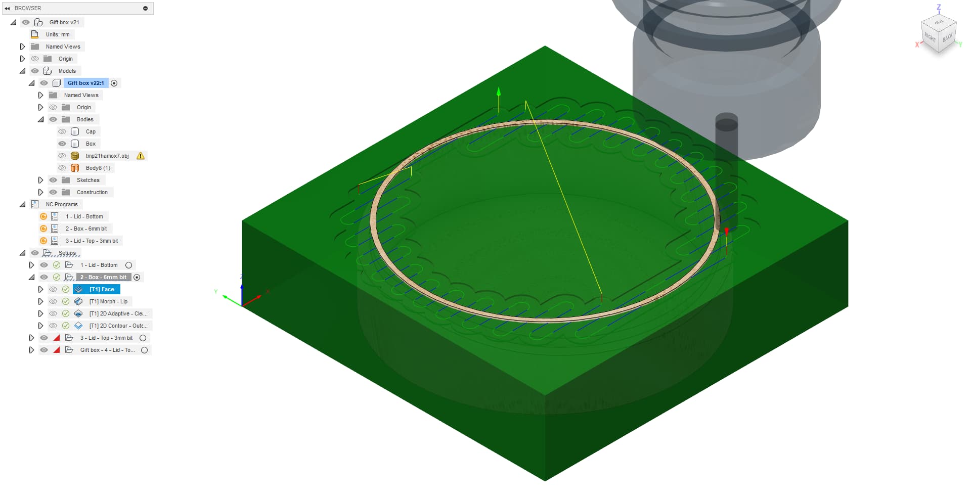
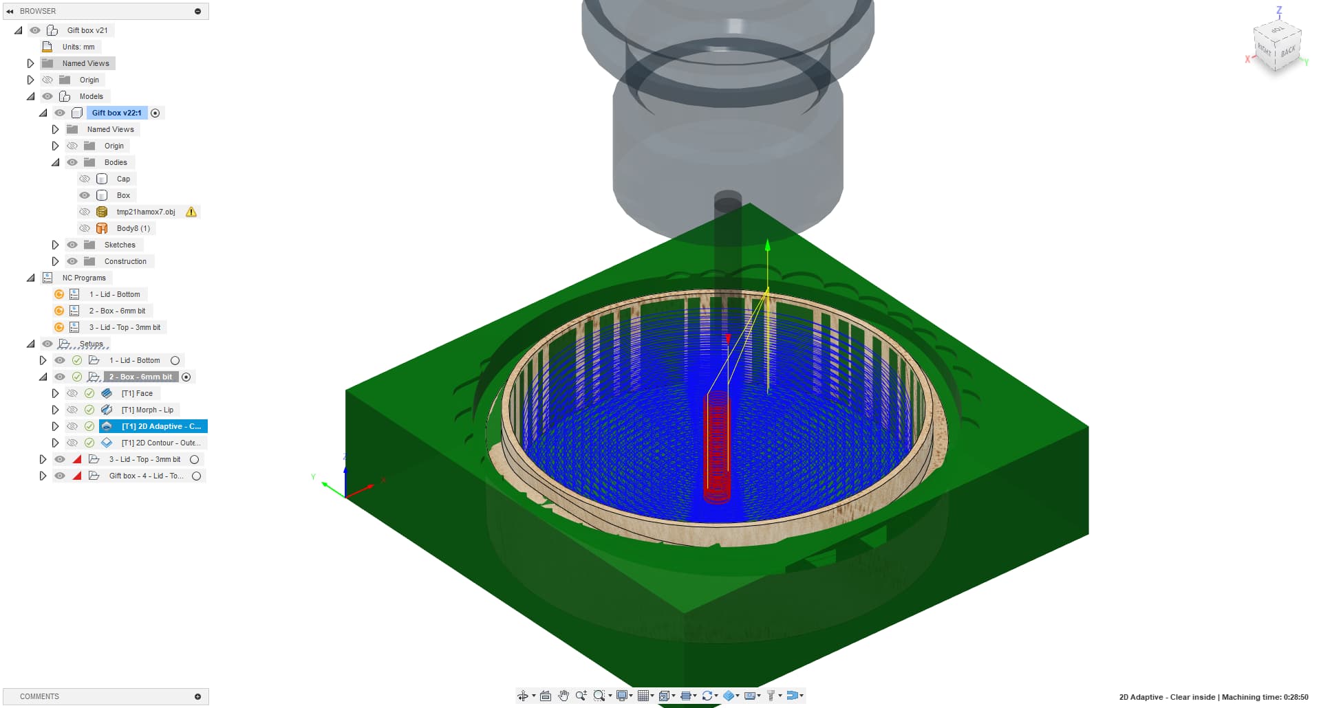
Third operation is once again a “2D Adaptative clean” of the inner pocket
Nothing new, pay attention to the depths and loads, try to optimize machining time…

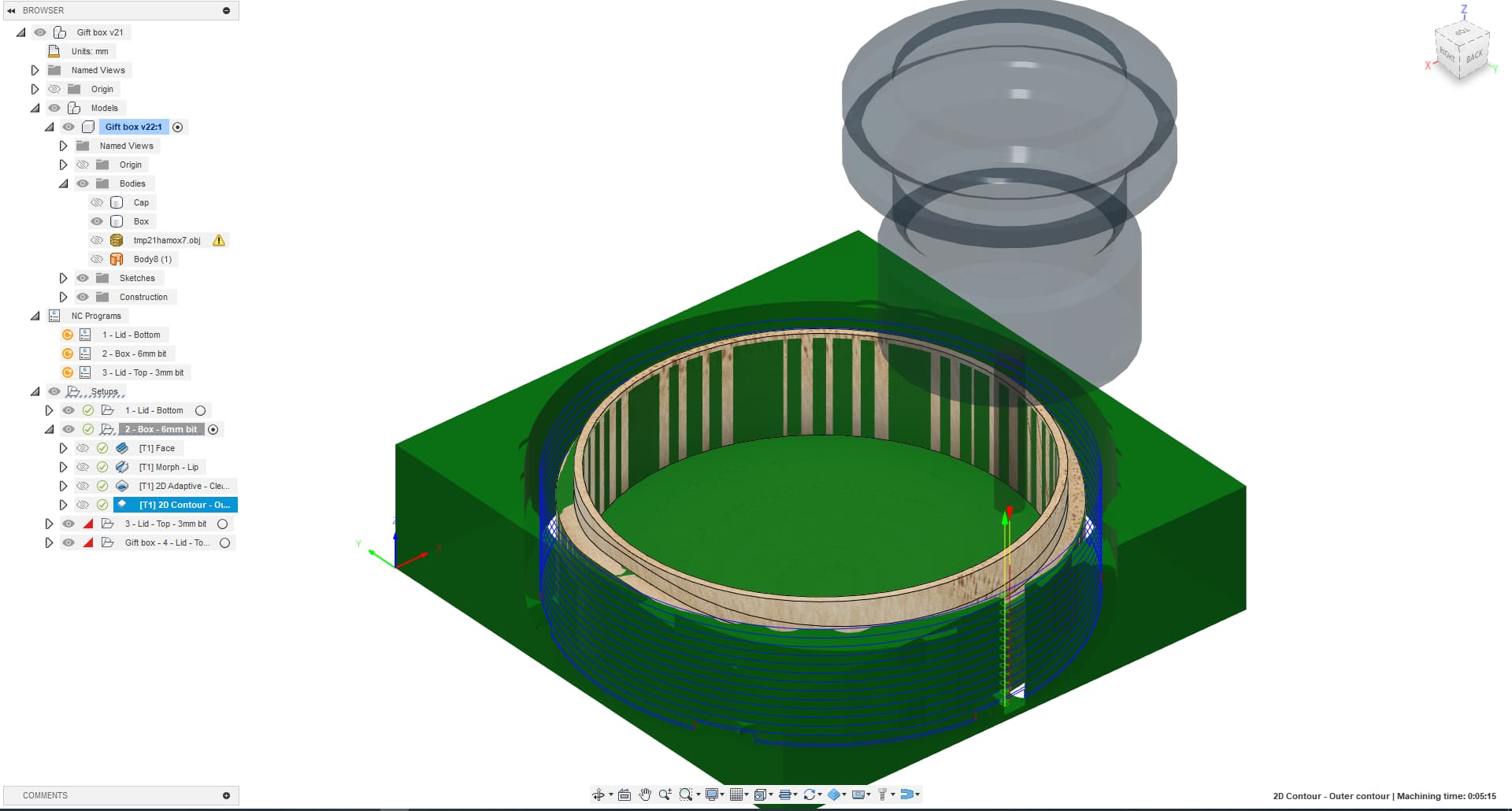
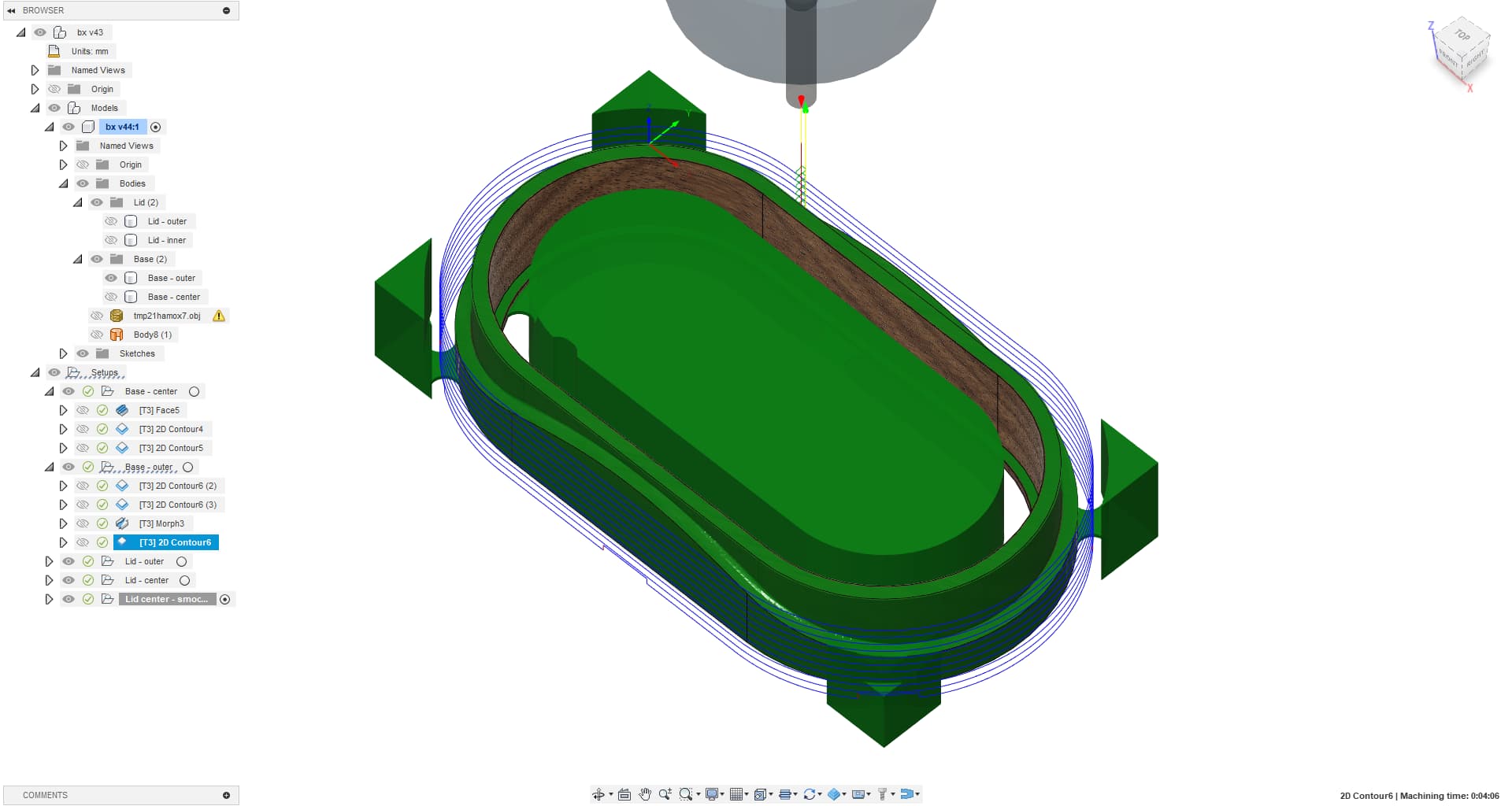
Fourth operation is a “2D contour”
Again, nothing complicated…

Except for one important thing: Activate the tabs, make plenty of them, make them big, make them tall!
image

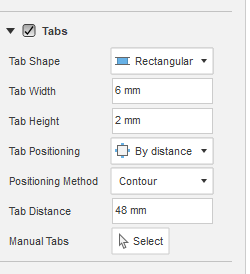
These tabs will ensure that the part stays put, as we will use it for the next operation…

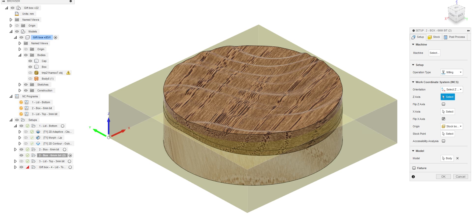
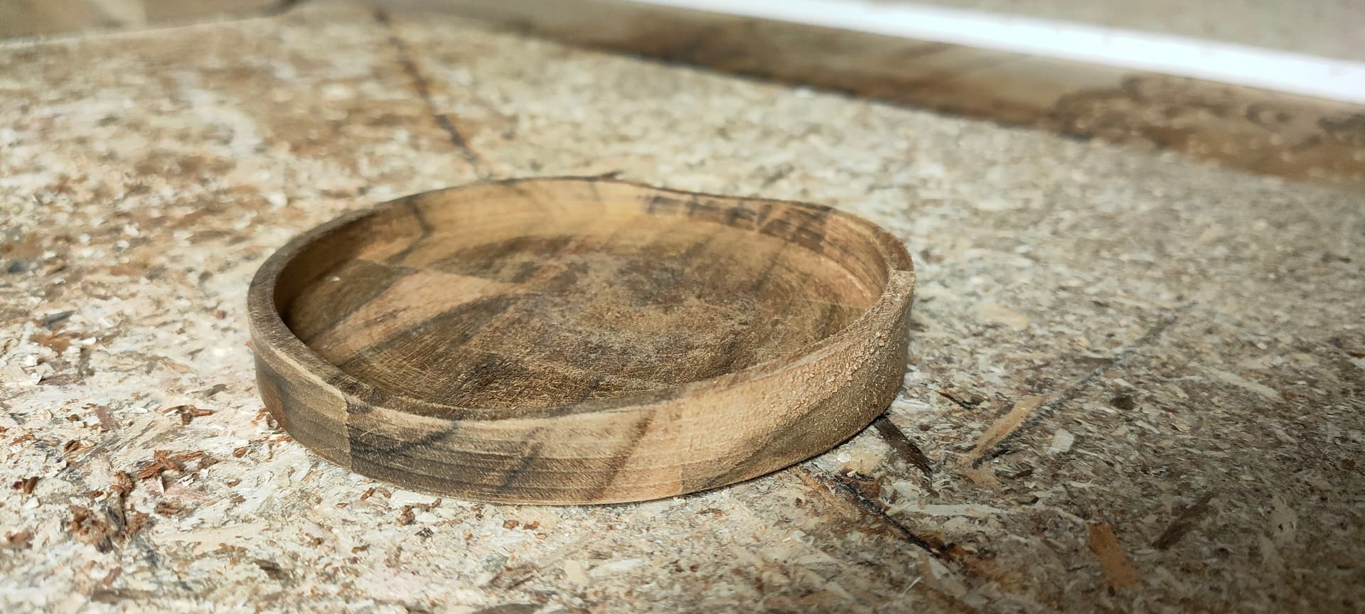
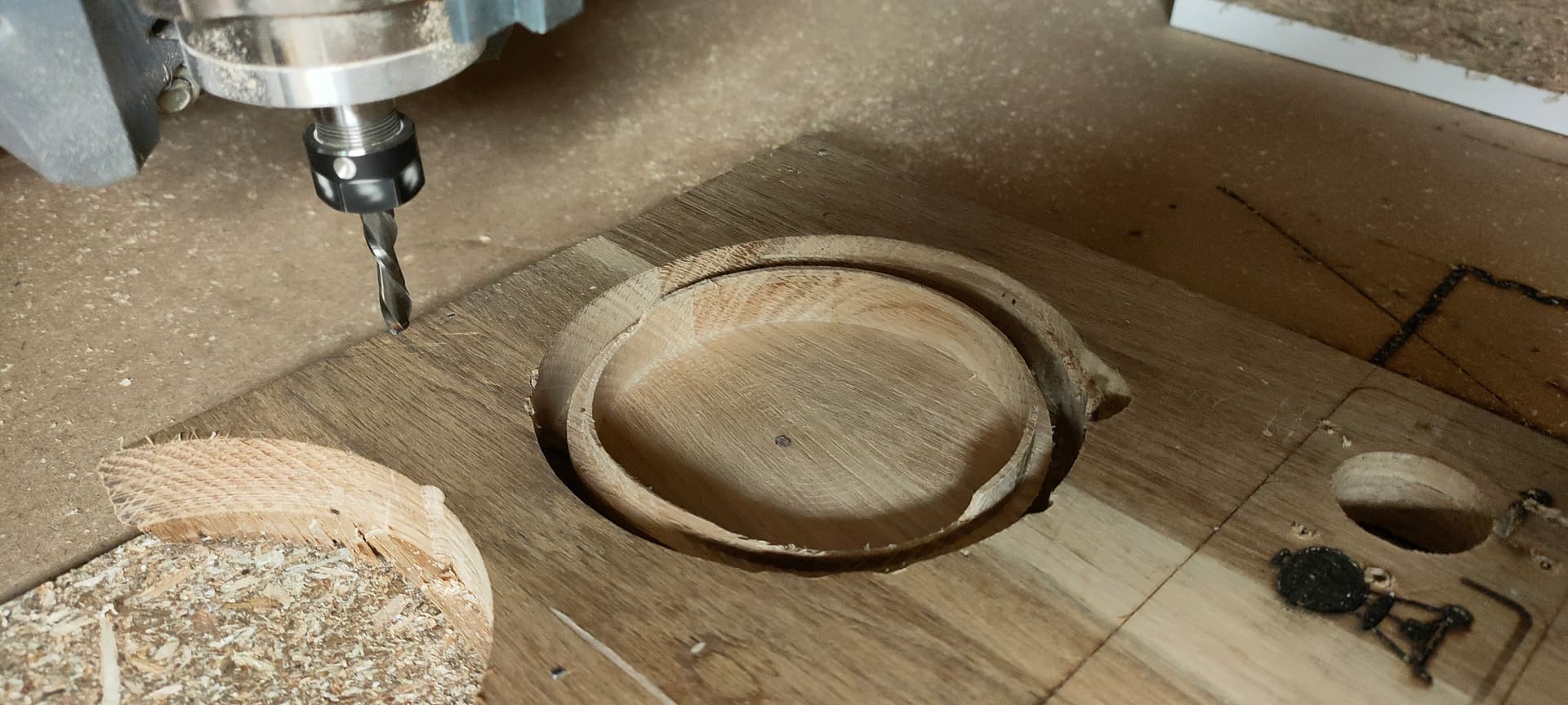
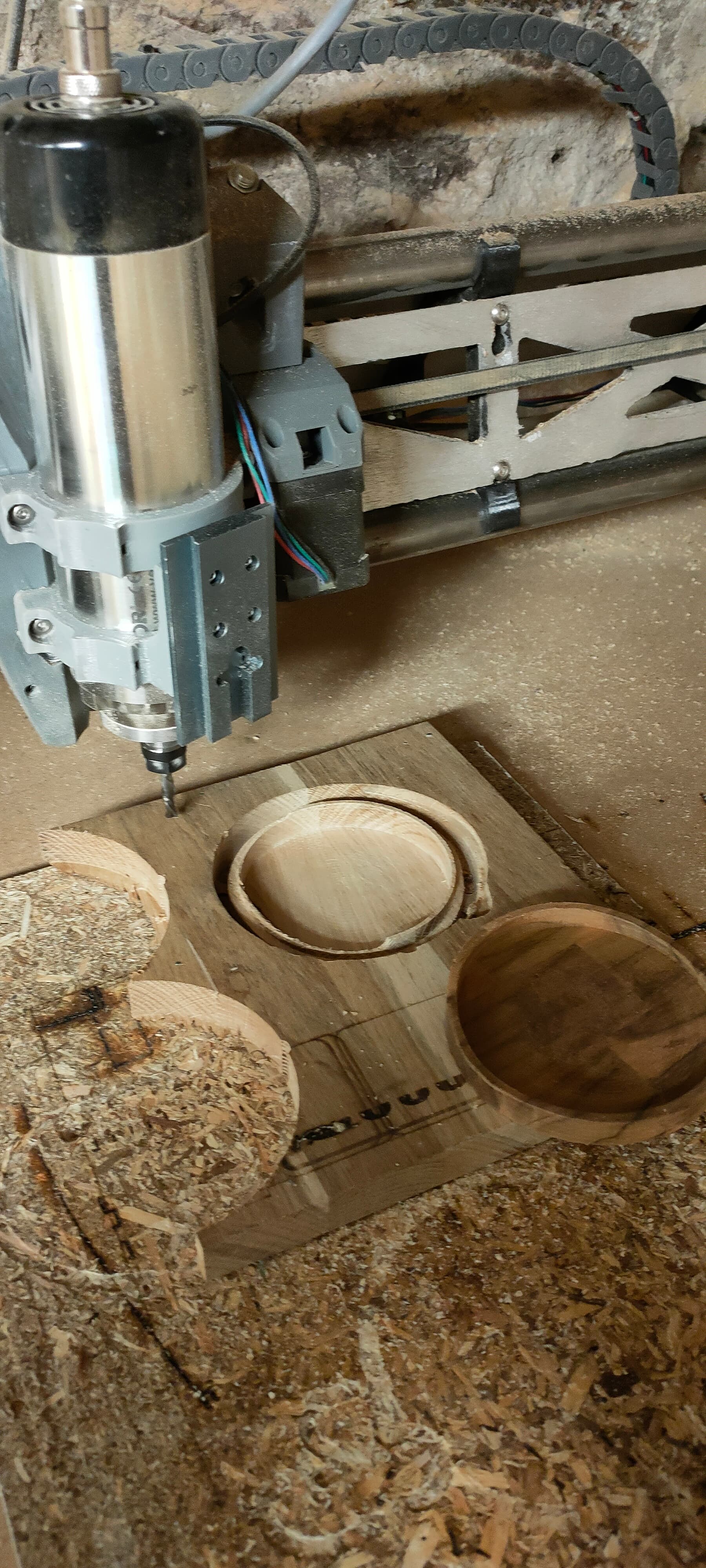
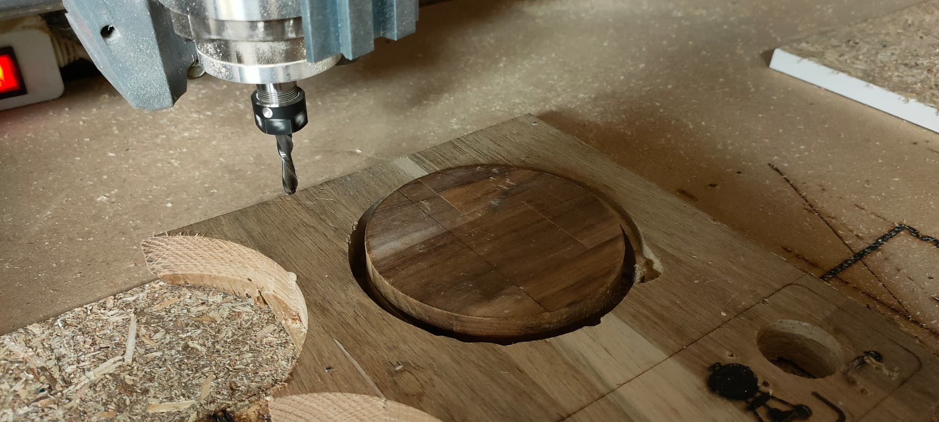
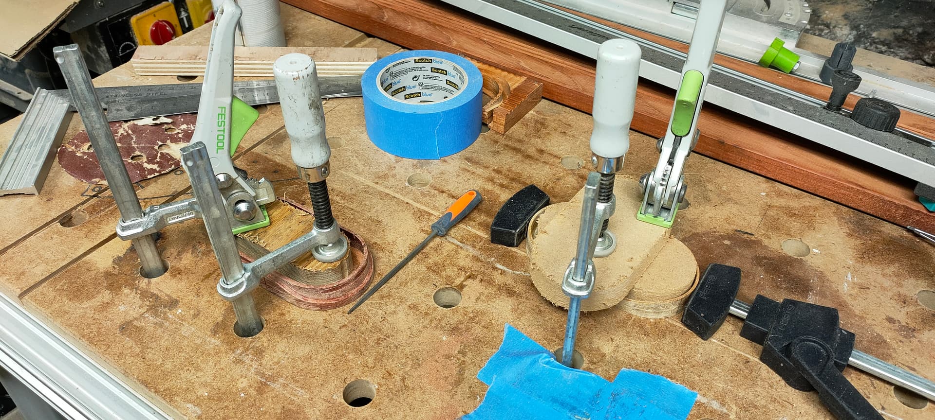
Third setup: Rough-carving the lid’s top

This is where the machining gets tricky: we will position the top of the lid by using the box itself.

Start by duplicating the preceding setup and removing all operations
This will ensure you get the same stock offset values, setup origin and everything as the previous setup…

This is critical, we want the coordinate system to be exactly the same, as we reference directly from the part machined in the previous setup

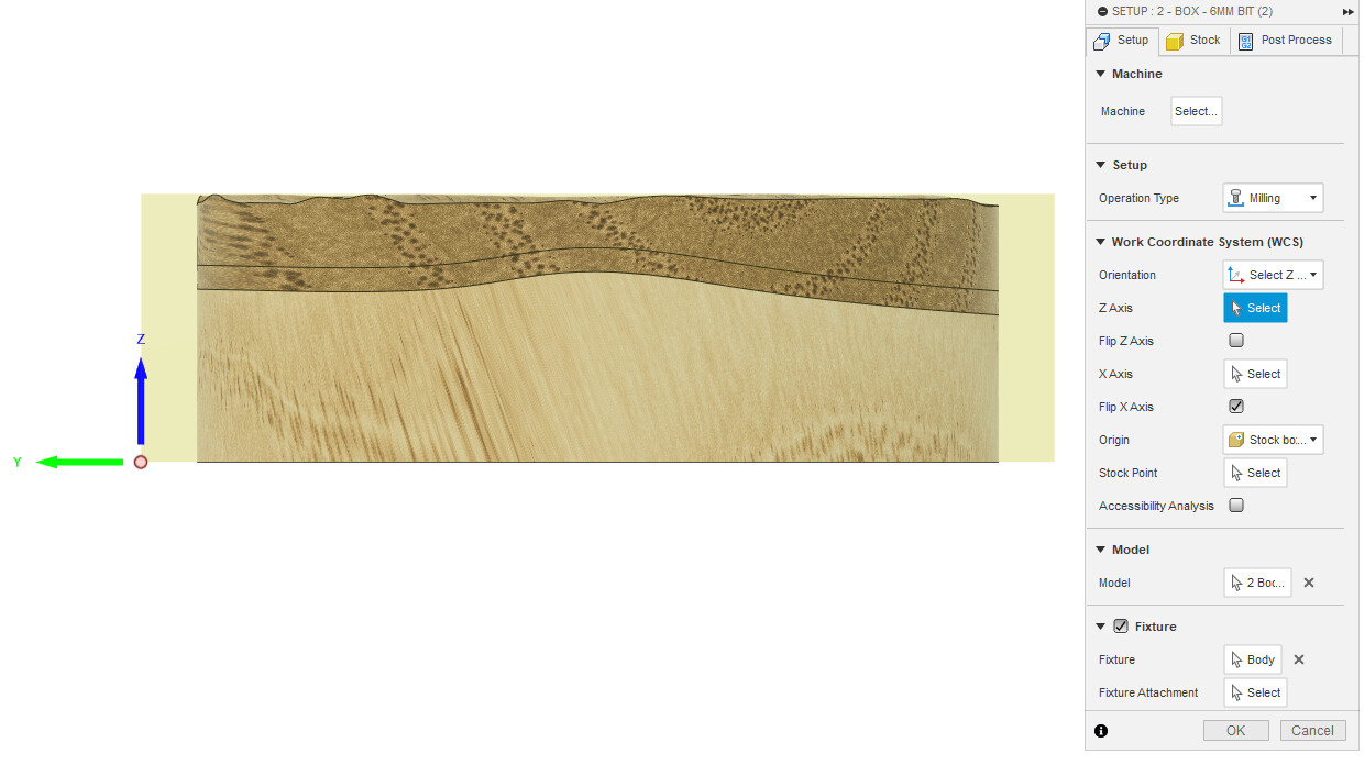
Add the box base model to the setup, declare it as a fixture

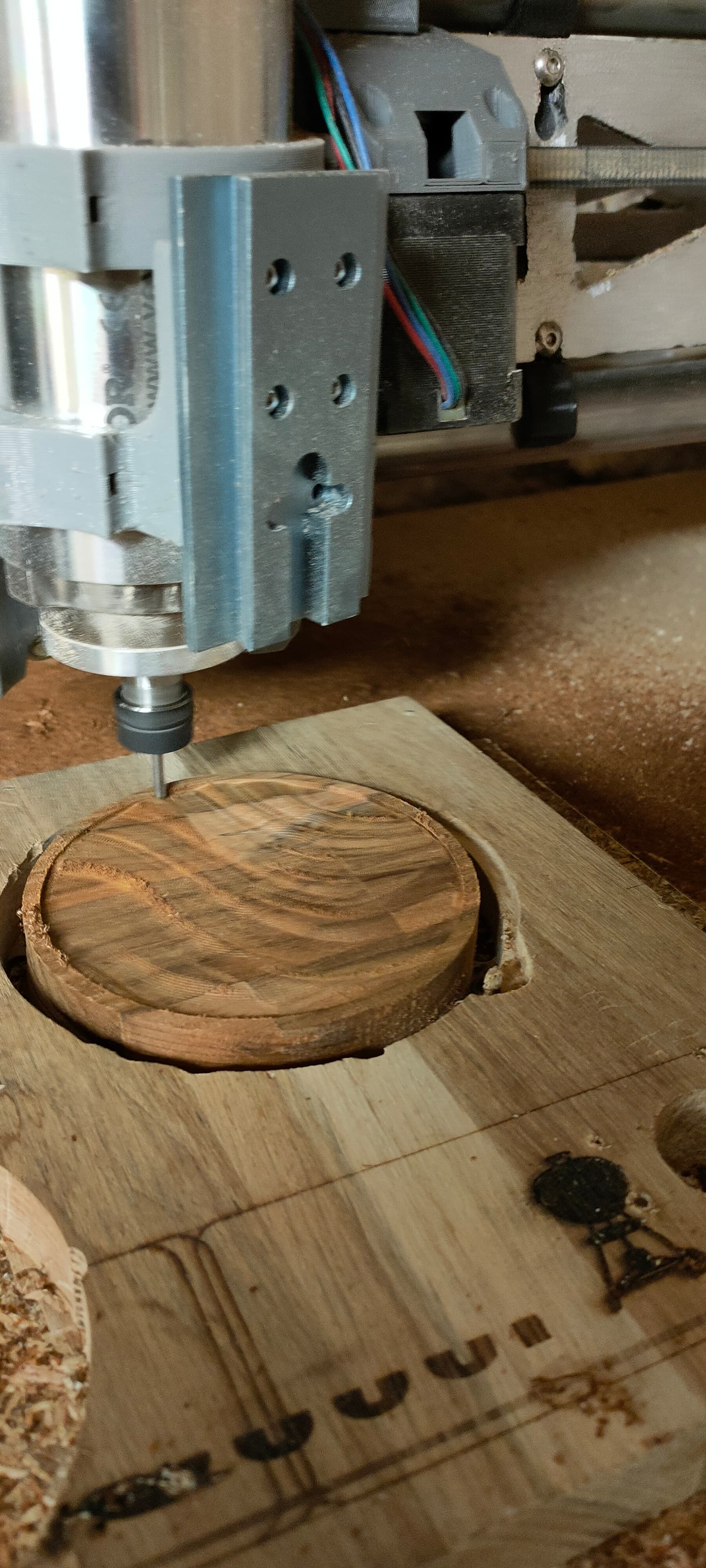
All operations in this setup use a 1/4" straight bit. You need a thinner bit to carve the details.

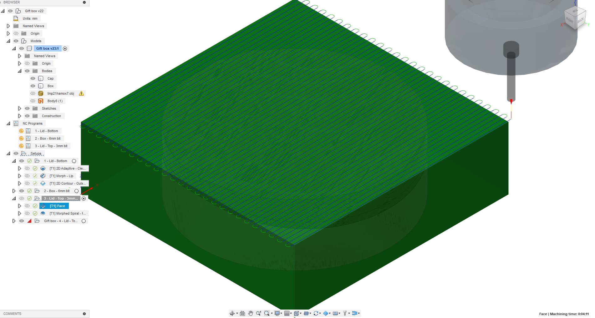
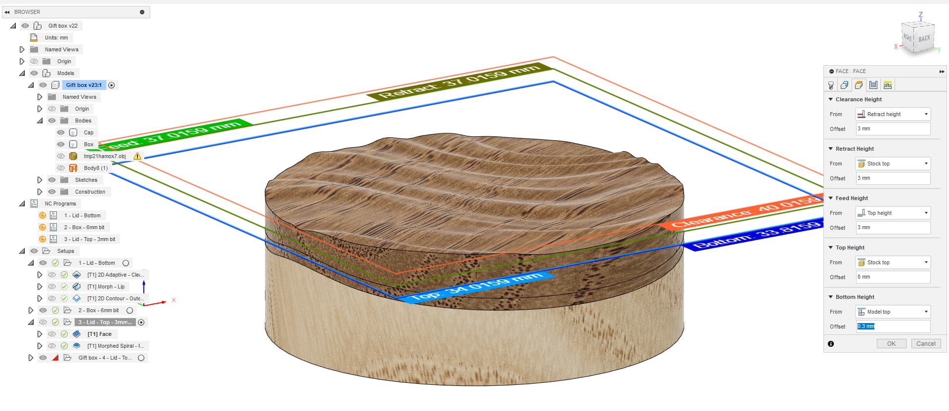
First operation: Surfacing

Surface the stock down to 0.3mm above the model’s top

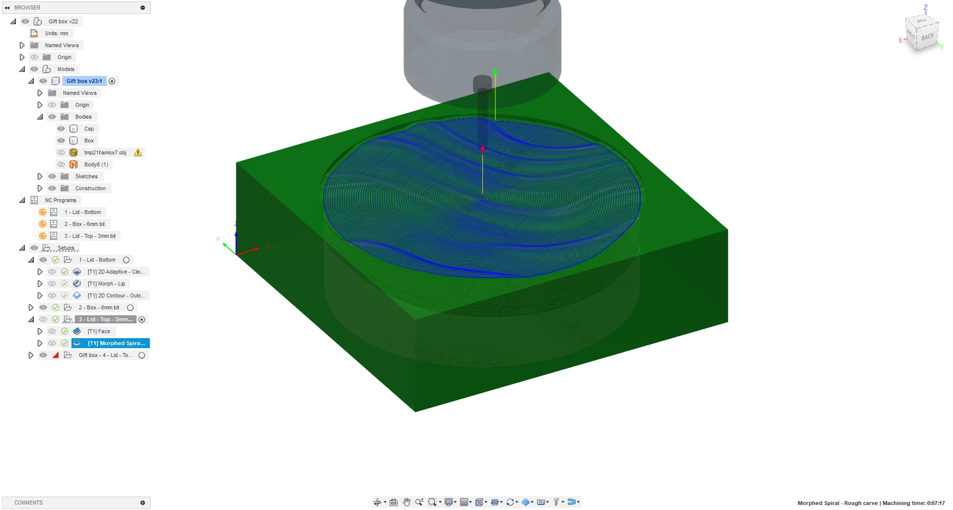
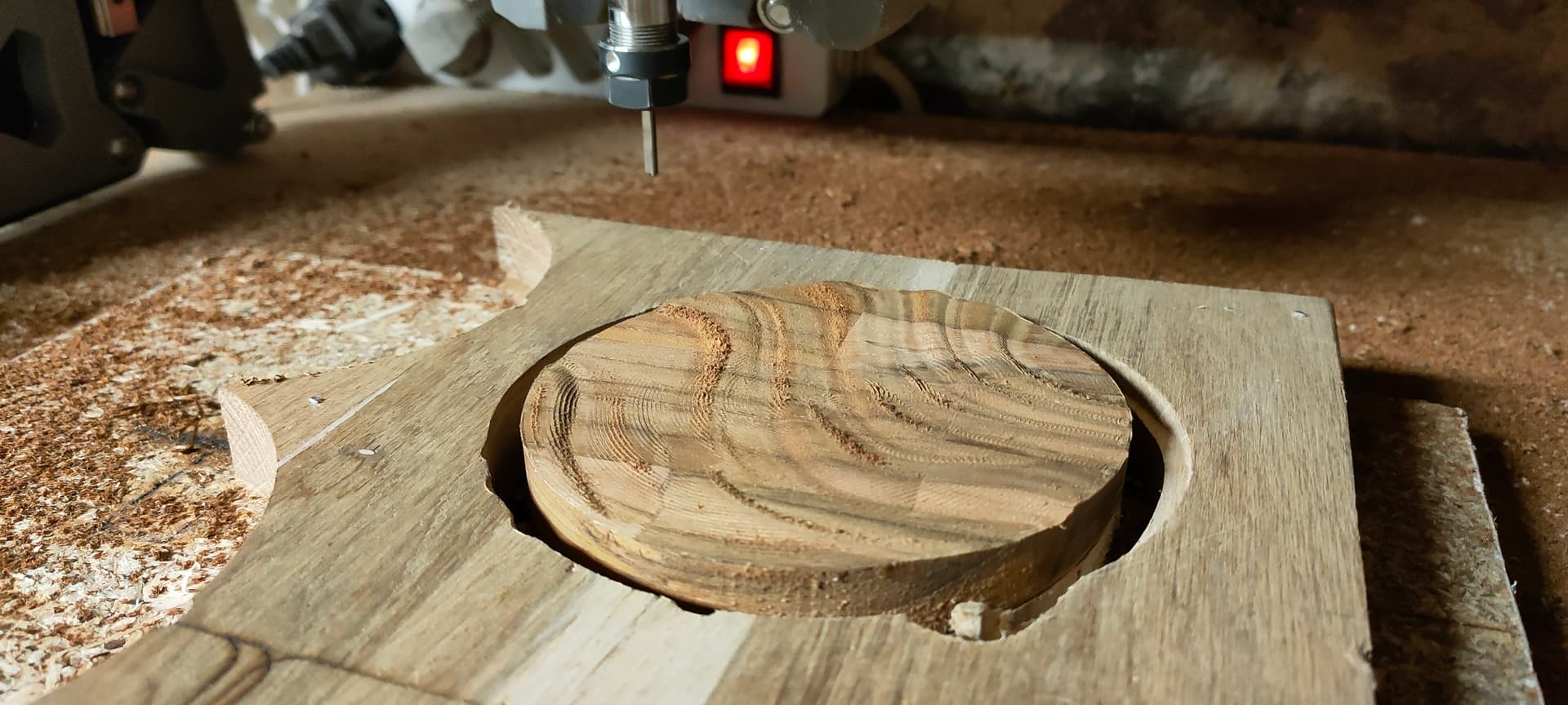
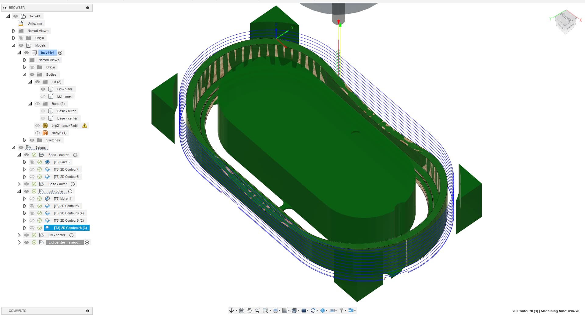
Second operation: Rough carving
Add a “Morphed spiral” operation

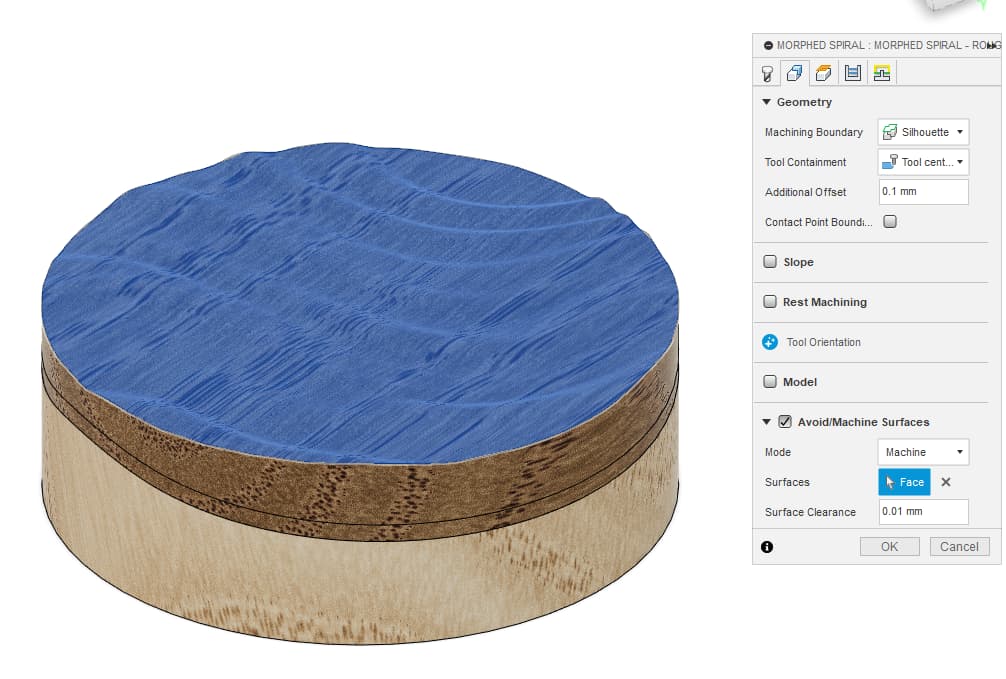
We want to limit the operation to the lid’s top surface. To do this, use the “Avoid/Machine surface” checkbox, select “Mode=Machine”, and select the lid’s top face

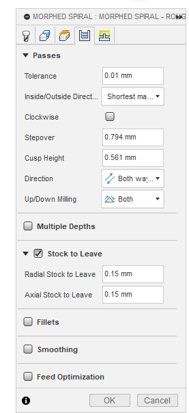
This operation will use a 0.15mm stock to leave (axial and radial) so that the last setup can take care of the finer details

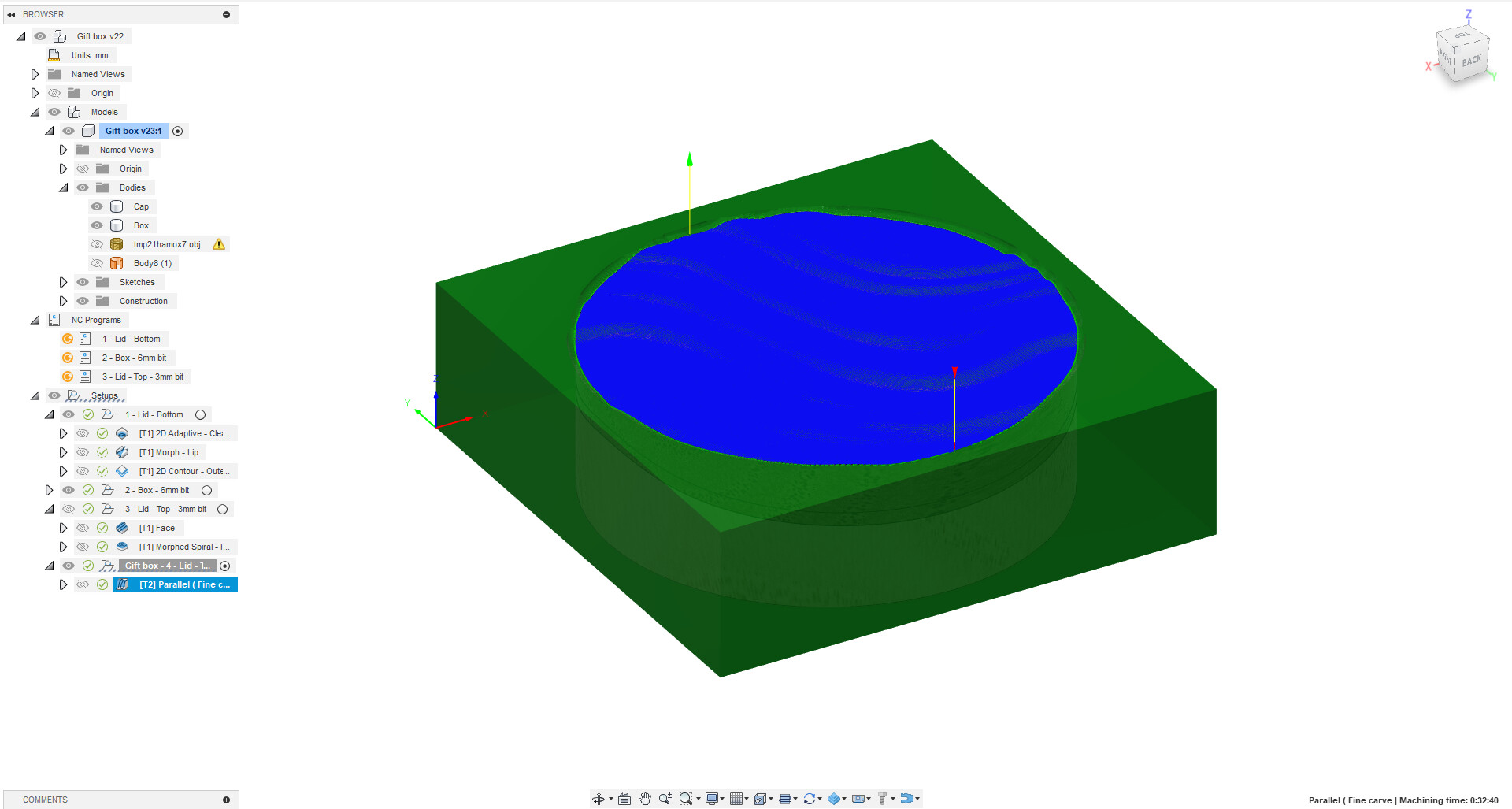
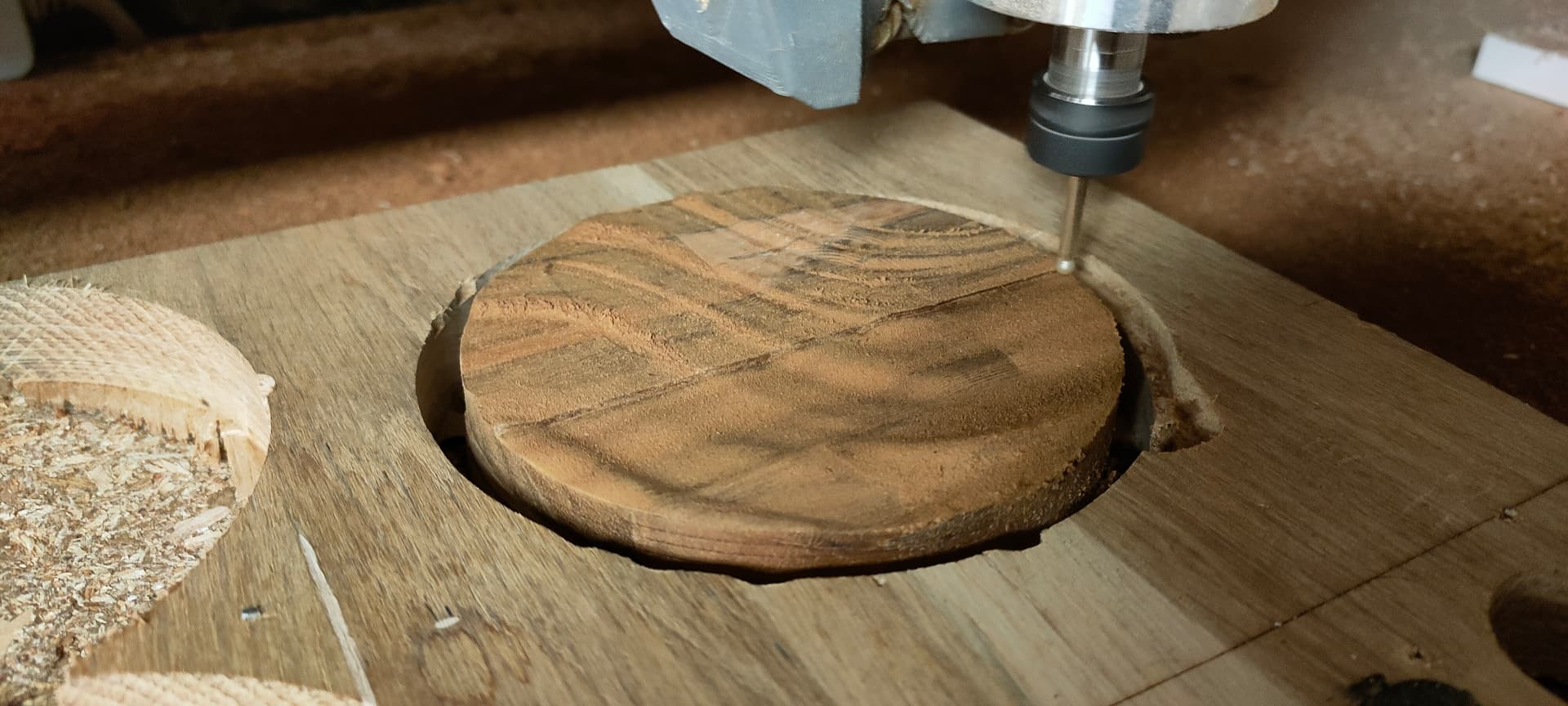
Fourth setup: Fine carving

All operations in this setup use a 1/4" “lollipop” diamond bit
You can use other rounded bits, but you need a small one

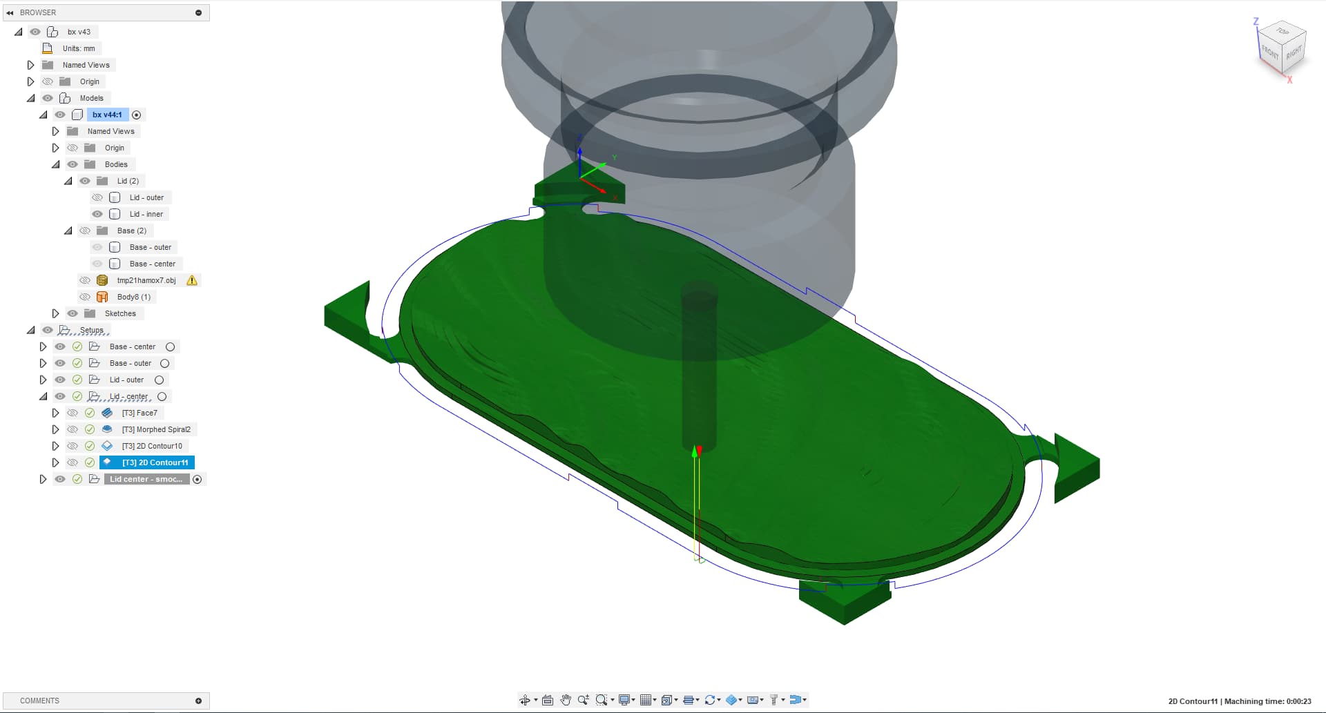
First (and only) operation: a “3D parrallel” operation that will smooth out the sharp edges left by the straight bit

The operation only removes a tiny bit of material, so you can go pretty high on the speeds
Just like the preceding setup/operation, use the “Avoid/Machine surface” setting to only carve the top of the lid

With all those setups ready and verified (always check the simulation! :p), you can now generate 4 gcode files and transfer them to the machine…

2 Likes

Machining the box

As per first setup, start by cutting the lid
I didn’t take a lot of pictures, as - except for the “morph” operation, this is pretty standard…

Second setup: cut the base, but keep it attached by the tabs
From now on, don’t bump the machine or screw up anything, as everything is referenced from this workspace :slight_smile:

Place the lid on the base.
If it doesn’t fit, you can export the “morph” operation once again with a negative “stock to leave” and run this single operation until it fits

Changing to a 1/4" straight bit and roughing out the top carving with the “morphed spiral” operation

Switch to a 3mm lollipop/ball diamond mill and run the parrallel operation

Some roundover on the router table, and a quick wipe with some mineral oil…

7 Likes

This is incredibly cool, wow. This is one of the threads I am going to bookmark, because I usually only think in 2.5D and not 3D when designing stuff. The pattern on the lid is reallly neat.

2 Likes

I refined the process a little trying to save another part I busted…
I think this has potential :slight_smile:

I separated the model in 4 parts rather than 2, alternating colors between center and outer part of the lid and base

A lot faster to cut too, as it’s all contours, no pocketing :slight_smile:

Base - Center → 2min40

Base - Outer → 13min03

Lid - Outer → 21min23

Lid - Center → 10min01
Lid - Center - Finishing pass → 23min55

Grand total: 1h 11min 19s

4 Likes

Cool! Great job!

I really like this Tali wood (bottom in the picture), it has an interesting pattern

Akola’s color is pretty cool too but apart from that it’s a bit plain/boring… and the dust is definitely very abrasive :confused:

2 Likes

More failures than I’d like to admit but the base is done

Need to cut the top part now …

And guess who broke the top half while sanding it ? -_-
Trying to save it with generous amounts of glue right now…

3 Likes

Not sure I really like it, maybe the colors should’ve been reversed?

1 Like

After a quick roundover and a few coats of varnish

I still think there’s something off with this design but hey, I’ll call this done…
On to some other projects now… :slight_smile:

8 Likes

I think it looks great! The only thing that feels slightly off is consistency in the grain direction. It might look better if the grain of the outside top went in the other direction.

1 Like

Noted! I plan on doing door handles with the same wood, and it might be a lot more visible
Thanks for the advice

I think it looks great. It certainly showcases your skills. But I think the piece is appealing on its own too.

How does it feel? Is it a nice fit?

You should be proud.

1 Like

I like it! I’d be happy to have that one in my list of projects complete I reckon.

On thinking about the grain - for a lot more work - I think the sides would be great with a vertical grain, so you’d have to glue them up “butcher’s block” style - and the top running lengthwise… (just thinking out loud in the hope you want to give it a go at some point! :smiley: )

Since the sides are pretty thin I think it might get too brittle then. Just a guess though. :slightly_smiling_face:

1 Like

You know I’m going to have to try don’t you? But not till we get back at the end of the month!! :smiley:

Looking great!

Yeah, it was meant as some kind of exercise anyway, kind of a “complication” If you will
It’s a nice showcase indeed, the end result is just a bit underwhelming given the time it took
I just like the round one better although it was much simpler :slight_smile:

The fit is good although it does not “snap”
I re-located the lid and took multiple adjustment passes until it fitted

There are a few hipcups here and there too, the curves do not exactly match, there is a small gap between the the carved part if the lid and the outer part, and the box is not perfectly symetrical, which is a bit strange

I though about it too, mostly because one of the goals with this second iteration was to save on material, but it makes sense aesthetically too indeed

1 Like