Ok i feel like a dumbass. I just changed my lowrider from the skr 1.3 to a rambo. On the skr i had a button on the touch screen to zero each axis before starting a job. for the life of me i cant find it on this screen. I guess i need to just get a usb extension and run it from the computer but i prefer to do it from the screen. Can anyone help me out. i have search and searched and cant find it anywhere. Thanks!!
OK got the USB set up and moved the pen to where i want to zero (trying to draw a crown) and i sent G92 X0 Y0 Z0 but repetier host doesnt show the axis at 0. What am i doing wrong? Thanks!
Repetier host doesn’t listen to G92. You can send a @isathome which RH will intercept and reset its zero.
The LCD should have a “set home origin” or something like that. I can’t remember which menu it is in. I use a raspberry pi on all my machines.
Pretty sure it’s in the V1 Custom menu.
Thanks Guys! Got it working!!!
Always wondered about this! Will help tons when I accidentally zero the z and y instead of x and y typing too fast and not paying attention.
Well, can you give us a follow the bouncing ball sort of thing on this one.
If I go to custom commands and select "reset all coordinates’. It beeps and does nothing which is fine.
So if I load G Code at this point it knows that this is zero, zero, zero?
ie .
- set up job plywood
- set router up and turn on.
- move router to xyz=0 ie where I reckon it should be.
then …
?
I have been un plugging the power and plugging back in. This sets it to zero. - Or
- Should I go to this reset all coordinates command. Click it.
- then load the gcode and it will start printing from there?
Puzzled.
Here is a video.
Rob
This is a good question. I assumed the V1Custom commands menu did what you are asking but I’ve never actually tried it yet. My build just got moved to my workshop (built it inside the house) so it hasn’t thrown and wood chips yet.
I’m very interested in the answer as well.
https://docs.v1engineering.com/learn/coordinates/
It beeps and looks like it does nothing, but if you have jogged around, it will reset the coordinates to zero.
There are many ways to skin this cat. Where you were resetting the power, you can use that menu item instead.
Yep. You can look at the first screen. It should show zero for all the coordinates. When you first start the machine, these flip between zero and ?, because it doesn’t know where it is, it just guesses zero.
Ryan likes to put a G92 X0 Y0 Z0 at the top of his gcode files. This just saves you from doing step 4/5, because the first thing gcode does is set the current position to zero.
What I do is this:
- Set up router, workpiece, etc.
- manually move the router to the edge of my table, where I know it is square. I also twist the z leadscrews a little to let each side lift and settle back down. This just makes it flat, or at least consistent.
- Start the controller. I make all movements with the controller from here on out.
- I jog away from the end of my table to enable the motors. Then I jog to the origin I want. Almost always the lower left top of the wood.
- Reset all coordinates. I use the G92 command, but the menu item is the same.
- I jog the Z up a little, start the router.
- Play the gcode file.
- Turn off the router and jog back near the start location. Turn off the controller.
I don’t have any endstops, so I don’t ever “home”.
I do have dual end stops and I notice it really helps with squaring my setup. With that being said, could I:
- Tell my system to Home itself (with end stops)
- Jig to where I want X0 Y0 Z0 to be
- Reset coordinates (manually in LCD or with gcode)
- Start job
Would that work? I’m not sure on the limitations of the end stops and if that over rides anything.
Thats how i plan to do it once i get my endstops working. the endstops help square the machine then as long as you dont do anything to disable the steppers it should stay square on its own. resetting the coordinates is necessary or it will try to start the job at the home position not where you jogged to.
Yep. The different in my setup is that I start the machine on my hard stops, which makes it square. Many people don’t realize this is an option, which makes dual endstops very attractive, but the difference to hard stops isn’t huge.
Your approach is perfectly workable. The only significant difference from @jeffeb3’s workflow is the use of end stops to square the machine rather than hard stops.
The real benefit of dual end stops is when doing repeated cuts. You would need a means of mounting the work piece in the same position consistently, but that shouldn’t be difficult. You could then use the end stops as your zero point, or at least as a consistent reference. For instance, you could put a G0 X5 Y5, followed by a G92 X0 Y0, to consistently start your cut 5mm from the end stops.
@jeffeb3 notes that he usually uses the top surface of the material, and lower left corner as his zero point. Just to provide some thoughts on alternatives, I’ll note that I often use the center of the work piece and top surface as my zero point. Especially when doing V-carved or engraved designs or text. Obviously, you must generate your g-code with this in mind, using the center as the zero reference in your CAM software as well.
Also, when doing through cuts, I often find it useful to reference off the spoil board. This minimizes damage to the spoil board. You can generate the g-code with this in mind, and call the spoil board surface Z=0, or just use it as a reference, but set the z to a negative value, based on the depth of cut.
OK, think I have it.
Will give it a crack tonight after work and report back.
Thanks again.
Rob
Great! another puzzle solved.
Thanks you blokes.
The reset all coordinates worked a treat. I think I am slowly getting this.
It’s funny. I have spent hours and I mean hours on Fusion 360 and am also starting to see a glimmer of light.
I have just received the 3D printed parts to put the foam skirt in to try and keep the chips at bay around the cutter head. I have this sort of feeling that the vacuum arrangement I have could be better. I am going to go and buy some bigger hose and see about making up an adapter to go between the hose and the and the router plate fitting.
Is there such a thing? What else do people do? I was thinking some sort of fitting that sort of came down around the front of the plate in behind a foam sawdust deflector would be good. Just that I have a bloody big vacuum cleaner and it sort of is sucking too hard around the corner through the little gap below the stainless cross X bar sort of?
Any top tips?
Rob
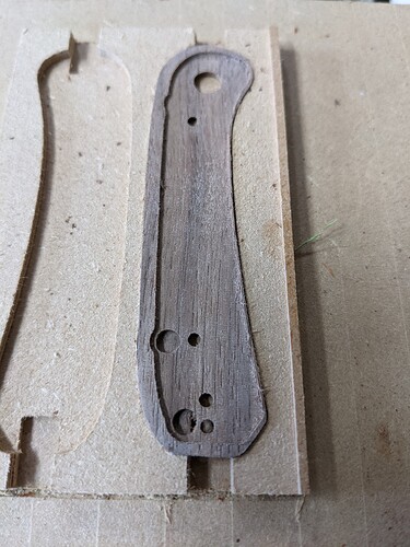
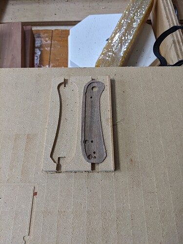
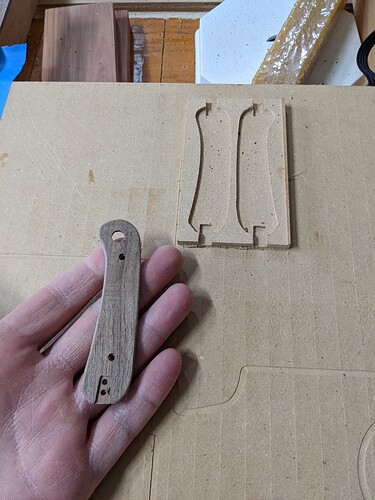
Sorry to drag up an old thread, but I was wondering if it’s possible to set zero to individual axis? I’ve got a fixture on my bed, and my zero point should be the top corner of the fixture. I want to touch off the x, zero it, back off then do the same for y, back off then do z. That will let me get the bit centered on that point more or less dead on.
Assuming your fixture is conductive and you have it wired as signal or ground, you should be able to do what you are suggesting using G38.2. If that fixture remains in the same place, you could just calculate the offset from machine home once, and then just move your machine to that offset in future uses.
unfortunately the fixture isn’t conductive, it’s MDF. I had machined ‘pockets’ or negatives of what I’m working on (trying to do a 2 sided machining), so once side 1 is machined/cut out from stock, I flip it over and put it into the fixture to machine side 2. I’ve gotten it close by eyeball, but still about 1mm off, maybe a bit less.
There are a number of approaches to solve your problem. If you just want something specific to this question, you can wrap the corner of your fixture in foil, and then attach a ground wire to that foil. On this forum, I’ve seen aluminum tape used for this purpose. But I have a feeling that if we knew the nature of your fixture and exactly what you were trying to do, we could offer simpler solutions.


