All the black pins along the “bottom” (in your latest image) connect to ground, which is electronically identical to the blue gnd pin you’re using.
I never meant to say those boards wouldn’t work at all, but that I personally have not been able to get them to work as Normally Closed switches. As long as you use them as Normally Open and connect them in parallel you should be fine.
Many machines have limit switches at min and max of each axis, so the designers of the shield made it easy to connect those machines with two wires per switch. As noted before, grbl can infer which of the two limit switches for an axis was tripped based on the direction of motion for that axis which grbl keeps track of internally.
I’m glad you’re having good luck in your project. One last warning - the 0.9 (and later) version of grbl enabled PWM control of spindle speed by swapping the Z limit and SpindleEnable pins on the Arduino. Protoneer released a version 3.10 of the shield that reflects this, but you can make it work on a v3.00 shield. I can’t tell which shield version you have from the photos. If you can’t get Z limit switches to work, plug them into the SpinEn pin.
The USB connection drops, or the machine stops moving and enters a locked state?
The latter is by design when hard limits are active. Tripping a limit switch (outside of the homing cycle) turns off the spindle and coolant pins and prevents further motor movement. You have to unlock the machine to continue.
If the controller itself is losing USB connection (or resetting), I’d suspect voltage from the LED circuit on the end stops is causing the problem but I don’t have any evidence to back that up.
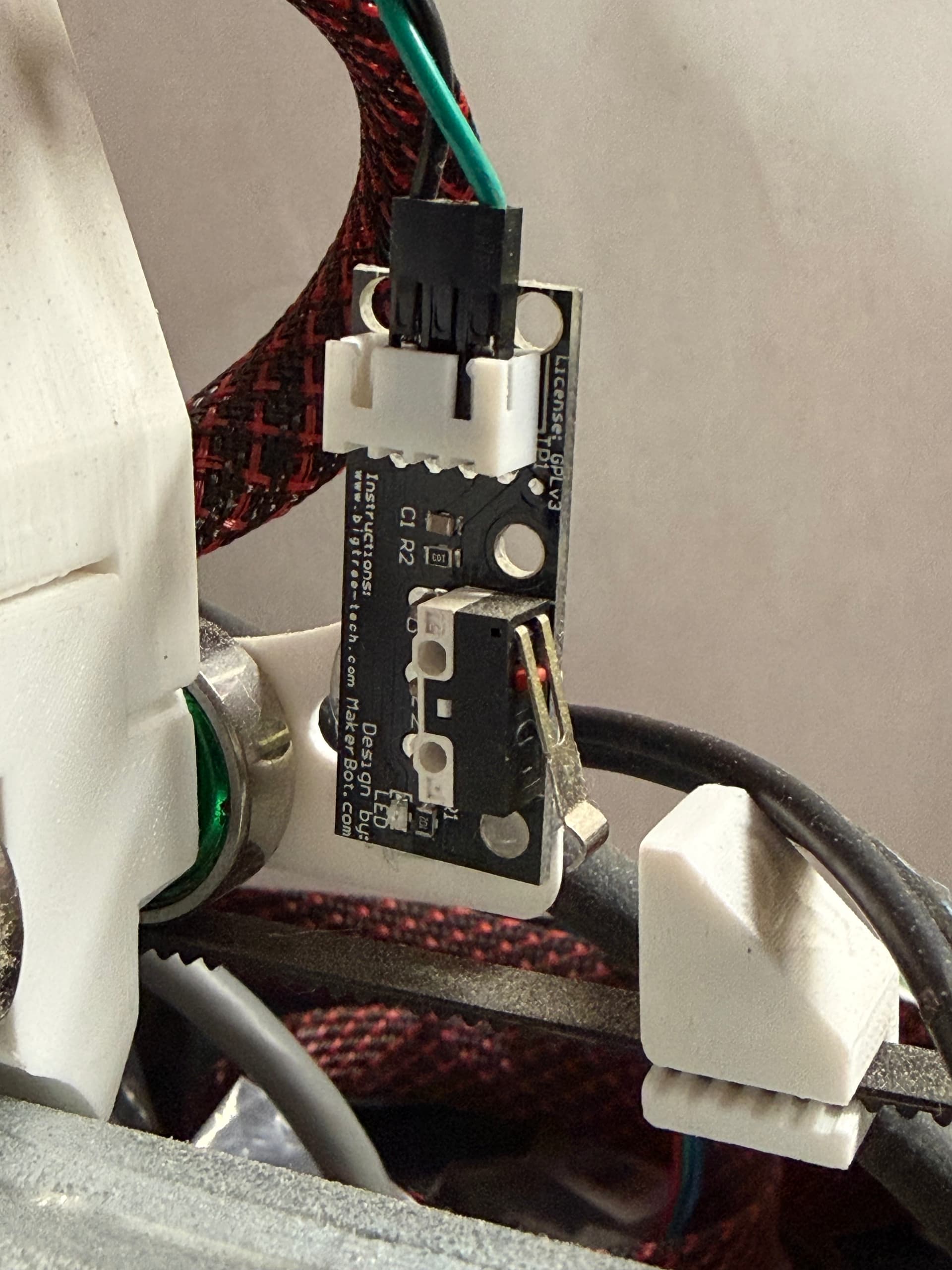
I found what was happening, the limit switch board has 3 outputs but these are not necessarily the same sensor output. In fact, there are 4 outputs on the board but 3 female pins for connection to the Shield V3.
This board only works by connecting to 5V (red wire), GND (black wire) and signal (green wire). In other words, 3 pins must necessarily be connected, and not 2 like the switch connections (COM and NO/NC).
The only alternative for this specific limit switch board is to change the command $5=0 to $5=1. In the first diagram I shared here, I connected it to the X+ (black pin) but it is to the white pin. I did so by connecting one sensor to the X+ (white pin) and another to the X- (white pin).
Anyway, all the tutorials on the internet show this end of course switch acting like this. I will share two links from which I extract this information. The first link, I realized that the same connection scheme that I mentioned was used. And the second (in the video) was used in parallel.
What I didn’t understand is that in GRBL the command $5=0 refers to limit switches that are set to NO. And I’m using it in parallel, I don’t understand why it worked. I believe these switches are developed for the purpose of controlling RAMPS circuit boards.
Hi, I am a beginner, I have the same type of problem with the limit switch, the same board and switch. From your description, should I understand that you cut the NC pins on all the limit switches and wrote $5=1 in the program? When I connect UGS, in IDLE, the LEDs on both Z-axis limit switches are on, and pressing any of them has no effect. When pressing any limit switch on x+, x-, y+, y-, UGS goes into ALARM, I have to disconnect-reconnect and unlock. In the setup wizard, enabling the limit switch, if I trigger any of x+, x-, y+, y-, UGS goes into ALARM, and I can no longer continue, the setup wizard gets stuck. Please, can you tell me what I am doing wrong? Currently, I am at the machine construction stage, without the motors connected with screws to the axes. Thank you.
Probably better to create a new topic than re-open one that’s 2 years closed… In that you should detail what board you are using, and how your firmware is configured.
These aren’t the switches that any of the V1 machines are designed for, they’re meant as active switches, used on some 3D printers, though I haven’t seen them used for a while. I still have a largish bag of them, and haven’t used them for years.
The switch on them is a pretty standard microswitch, and probably better to just use those. They’re cheap, so it’s not an expensive choice.
You did not specify, but I will assume that you are using FluidNC. On as Jackpot board, the default firmware configuration is for a NC (open trigger) switch. If I remember correctly those switches are set up to sent +V triggered, and ground untriggered. They are NOT configured to be usable in series at all, and some hacking is required to do it. This is more trouble than it’s worth. Even more so for V1 machines that don’t mount these things in the first place.
The Jackpot is configured by default to use a regular microswitch with ground and signal pins. A pullup resistor brings signal to +V when the switch is opened, either by being triggered, or disconnected. Therefore only 2 wires to the switch are needed, and should be connected to C and NC on the switch, with NO being left unconnected. I like to connect the Signal wire to C and the ground wire to NC. (This way if you connect 3.3 or 5V to NO, the logic continues to work, and nothing gets fried.) It doesn’t actually matter if you only use the 2 wires though, as long as they are connected to C and NC. To put these in series, Run signal to C and run a wire from NC to C on the second switch, then from NC on the second switch to ground. In this way, if either switch is triggered, the circuit to signal goes open, which the board reads as triggered.
If you’re using the CNC Shield v3.00 board with newer grbl firmware (which was what was being discussed in this thread you’ve resurrected), the Z end stop and SpindleEnable pins were swapped by the firmware developers to allow for PWM control of the spindle. This is why clicking the switch has no effect - it’s plugged in to what the controller believes is the spindle speed output, and nothing is connected as a Z end stop. Plug your Z end stop to the pin labeled SpnEn and you should be okay. The alert behavior is “working as expected” under grbl - the machine should stop and alert if you hit any of the limits, except as part of the homing cycle. (Note that this is different from the behavior of the other firmwares discussed on these forums, where the switches are only monitored during homing and are not active any other time.)
If the switches you have are built on to circuit boards with LEDs, I was never able to get those to work as NC switches. They worked fine as NO switches, but then you need $5=0. I cut the switches off those boards completely and then wired just the bare switches as Normally Closed (using the NC and Common terminals) with $5=1.
Thank you for your help, I am using Arduino Uno, Cnc shield v3, 6 limit switch 3 pin MakerBot Design, Grbl 1.1., Universal G-code Sender.
  I cut each NC pin of the limit switches on the limit switch board.
  I moved one of the limit switch z to the SpinEn pin, the other limit switch z to the D12 pin, but I had to connect the GND for it in the black GND row, in the blue GND row I could not measure GND against 5V.
  Now when any limit switch on the same axis is pressed, the LED lights up on both limit switches of the axis and the UGS enters the Alarm status.
  This operation is valid for each individual axis.
  As I said, I'm a beginner and I'm going to discover the program settings and the operation of the machine. Now I'll have to check if the whole assembly will work correctly when connecting the motors.Thank You Agaton.
I think you’re coming through the translator clearly enough. I hope my comments are making sense when you translate them.
I need to correct my earlier statement - I just went and looked at the machine. I am using the switches as Normally Open. For the X and Y axes I did mount the makerbot circuit boards, but only used the S and G connections.
The LEDs don’t get any power so they don’t light up.
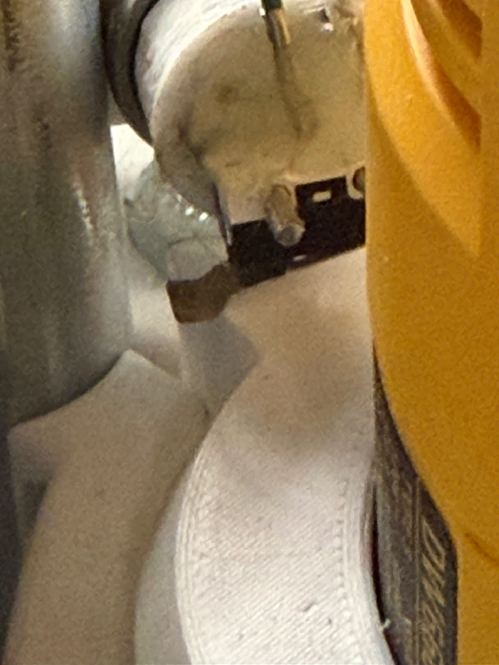
My Z axis homes “up” away from the cutting surface. I clipped the switch off the circuit board and mounted it to a 3D printed bolt cover sorry if the photo is blurry - space in there is very tight on the Burly model MPCNC and I tried to zoom in to show the switch. THere’s a big glob of hot glue around the wire connections to insulate them.
I only use one switch on each axis. For X and Y I have set the soft limits to one millimeter shorter than the physical travel of the machine. For the Z axis I have a probe wired to the SCL pin on the CNC shield, which grbl has mapped to the probe function.