How to connect these limit switches in series?

Well, I’m assembling a CNC and I need to add the limit switches, but I’m unsure.

Let me explain, the CNC works in a CoreXY way, which means that two motors work in sync. For each limit I intend to place an end switch, then… 4 limit switches, 2 for the X axis and two for the Y axis for example.

Ik, I should put them in series, right?

Important Notes:

  1. I’m using GBRL v1.1h
  2. The control board: Arduino Uno+CNC Shield V3
  3. Limit switch model: MakerBot type (3 pins)

My CNC uses three 12V stepper motors and is an “Axidraw”. Should I worry about the famous ?

For CoreXY kinematics, there isn’t much point in dual end stops. You might as well just put one where you’re sure to hit it.

For normally closed switches, you can wire 2 or more in series, because it will trigger no matter which switch opens.

For normally open switches, you wire them in parallel, so that again, it will trigger no matree which switch closes.

Unless, of course you only want the case where all switches are needed to triger a stop.

However, the more switches you have, the more points if failure you have and the more difficult it is to troubleshoot when something goes wrong. I would only use one switch per axis. This is especially true with those 3 wire switches. Wiring more of them together in series will result in a mess, and wiring in parallel will result in shorting 5V to ground. The 3 wire switches sometimes have adequate protection to avoid the worst cases when shorting to ground, but will definitely not produce reliable results even if it doesn’t blow a regulator.

1 Like

I know it doesn’t make a lot of sense, but in this work my project teacher wants two limit switches, one for homing and other for limit axis. My question is, to put them 2 in series I need to connect two of the green wires (signal) to the same pin (X+ or X-) on the board and at the same time the black wires (GND) and red wires (5V) doing the same thing?

I really need two limits (in this case 4 - 2X + 2Y) because this is a school project. Unfortunately, my teacher only wants it if that’s the case.

(This is all that’s needed to complete the project)

Wiring signal pins from 2 switches to one connector on the controller is parallel, not series.

I have not had good luck trying to use those LED-enabled limit switches in normally-closed configurations, and I don’t know that putting them in series would work due to the additional circuitry. I use “naked” microswitches with the CNC Shield on my MPCNC Burly.

My reading has shown that wiring several NC interlock switches in series works for safety switches - you get one loop and any break in the loop triggers the safety interlock. With end stops you’re going to want to be able to tell which one tripped, so linking them all together makes interpreting that more complicated. The CNC shield labels switches as min and max for each axis, but in fact only has one pin for both directions - GRBL has logic based on knowing which direction an axis was sent to move in, so it can discern min from max from a single switch.

You will need to use a 2 wire switch. Just a regular microswitch will do.

So basically you want a minimum and a maximum, and use hard limits on the machine.

Normally closed configuration wires in series. Both switches conduct from signal to ground (typically) and a pullup resistor is used to make the signal logic high when it is not shorted to ground. This will produce a logic high because the circuit from signal to ground will be interrupted when either of the switches become triggered.

There is a downside to this. Since the control board cannot know which switch is open, if the machine is at an axis maximum (IE, the opposite switch is triggered) it will think that it is at the home location, instead of the opposite.

It may be better to re-purpose the Z and A stops as X-Max and Y-Max. Tghis will require some fiddling with the firmware, but can do what you want.

Uh… No. Normally OPEN switches, maybe, but not 3 wire ones. The 3 wire switches do not need pullup resistors, because they take the power source to send logic high to the signal, and ground to send logic low.

Consider 2 normally closed switches in parallel.

Both switches conduct from signal to ground. Result, logic low.

Trigger one switch, and it opens, but the other is still conducting to ground. Result logic low. you would need to trigger BOTH in order to see logic high from the pullup resistor.

For a 3 wire… Both send logic low. This is OK. Trigger one, and one sends logic low to the signal, while the other sends logic high to the same pin. Fzzzt! Pop! This is a bad combination, pure and simple. Some of these do have a resistor between power and signal, and some (as I discovered to my chagrin) do not. The logic pins just sense voltage, so they’re OK with this, so long as nothing else (like another switch) is shorting the signal to ground. I can’t think of any good way to put the 3 wire ones in series, either. The only way I can see to use them is by using an OR gate chip to send logic high if either one (or both) send logic high. That isn’t a difficult circuit, but it’s needless when a simple passive switch is WAY easier to implement.

My reply was meant to convey “that won’t work the way you’re expecting.” Your reply is more precise and details the even worse consequences.

I created this diagram, I don’t know if I did it right, but the logic seems to be correct despite the system not knowing which limit switch was activated. It activates both because it is connected to the same signal pin.

Again, I need physical homing and not just virtual homing. If I give an X- command in the Universal Gcode Sender it will “hit” the structure.

One question I had, to put them in series, if I put one in X- the other in X+ on the black pin of the Shield V3, would it be in parallel, right?

Ok, consider this:

Normally both switches short black to green. No problem, green takes on the 0v potential of the black.

When one switch is triggered, it shorts the red to green, but the other still shorts black to green. The result is shorting red to black. This is bad. Even if there are protective resistors on the +5V potential red wire, the control board will never see logic high unless both switches are triggered.

To get the series logic, the green wire from one switch goes to the black of the second, and the green from the second goes to the control board. The LEDs on the switch boards probably will not work, and the whole setup may not work, depending on the specific components.

Nope. Way better to use a plain microswitch.

Edit:

I see on that diagram that you have X+ and X- as well as Y+ and Y- inputs… why not just use those?

So what you meant is that if I make the same connection as in the diagram but instead of the green pin of the second switch it is connected to the same black pin X+ I will have to connect it to the black pin X- right?

ok, way better to use a plain microswitch… but how will GRBL understand the left and right limit without homming command?

While written as if they are separate on the silkscreen of the CNC shield itself, each axis only gets one pin on the Arduino for end stops. X+ and X- are shown as separate but are electrically/electronically identical (as can be verified with a quick continuity test). The white pins are for the signal and all those black pins are common grounds.

Look into the grbl configuration and homing cycle documentation. From what you’re describing I think you want both hard and soft limits enabled, with switches at the physical travel extents of each of your axes which will establish the overall movement envelope of the machine. You can then use an offset to set a “home” position somewhere inside the envelope with a gcode command (not a grbl setting).

On my Burly, I have one NO switch each for X, Y, and Z and control max travel by enabling hard limits ($21=1) and soft limits ($20=1) and setting travel distance limits ($130, $131, $132 for X, Y, and Z respectively). If you absolutely need limits switches at both ends of travel, use NC switches (not circuit boards) wired in series as shown in the first diagram on the grbl Wiring Limit Switches page. The diagram pictures show the Arduino rather than the shield you’re using, but the pins are properly identified.

I’ll say again that I tried and was unable to get those 3D printer LED-enabled end stop circuits to work properly in an NC configuration even when I tried the other unused pin on the connector - current seemed to leak out from the wrong side of the LED when the switch was tripped and it just didn’t behave properly for my needs. I ended up just cutting the switches off and using them without the LED circuit.

My question is because I always think about all the possibilities. I understood your point, but if the machine axis is moved in any direction and the point is reset (zeroing the axes), it no longer recognizes this virtual homing. I could be wrong, analyzing various types of CNC I came to the conclusion that the best safety for the machine is to “enclose” all its limits.

On this board, how would you recommend inserting the Shield V3 switch pins? If I am unable to insert two limit switches, I will only use one.

(allow me a mildly didactic tangent for a moment) It’s important to remember that several generations of smart engineering folks have been working on CNC and gcode for decades. Chances are if you’re coming up against a problem for the first time, someone else has already solved it. The down-side is, the “by the book” solution probably has a whole lot of (really cool, if you need them) esoteric options that it can be tough to wrap your head around. It sometimes takes investing some energy in understanding some pretty dense documentation for it to truly make sense.

If you use work offsets to set the interior location of the job, this work offset is understood to be in relation to the overall machine movement envelope and soft limits will be honored.

(on a slightly different tangent, bear with me. Sorry if you alreayd know this, but not everyone who might come across this in a search will) The micro switches usually used for end stops have 3 terminals. When the switch is in its resting (normal) state, the Normally Closed terminal is electrically connected to the Common terminal, and the Normally Open terminal is isolated from the Common terminal. When the switch is triggered/activate, the NC terminal loses connectivity to Common, and the NO terminal gains connectivity to Common. Under normal use, NO and NC should never have a connection between them.

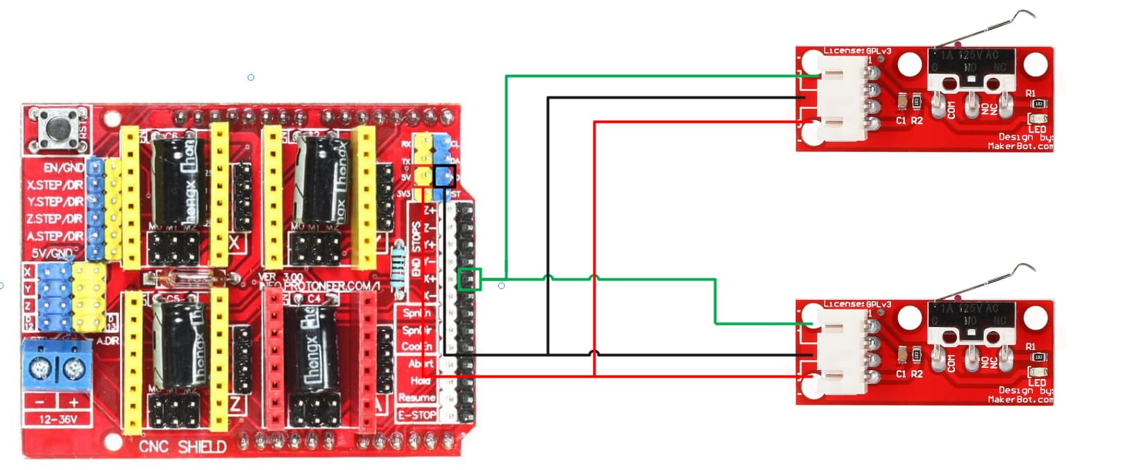
(now to answer the question you actually asked - thanks for your patience) As far wiring the switches, “signal” (the NO or NC lug) connects to the white pin and “common” (the COM lug) connects to the black one on the shield. If you’re using simple switches it doesn’t really matter which is which, but if you’ve got those 3d printer endstop circuits, or a PINDA probe or hall effect sensor, or something else that needs a reference voltage, then it matters. You can get that refence voltage from the 5v (yellow) pin you identified in your picture.

If you go with the first diagram on the Wiring Limit Switches page I linked before, you’ll only have 2 wires to connect to the shield for each axis, so one to white and one to black on whichever axis it makes sense for. Notice how tripping either switch opens the loop by breaking the connection between signal and ground. Grbl notices this change in state and takes whatever action has been defined.

You can also use one or two NO switches per axis, as in the second image. On the shield, this would look like each switch having 2 wires run, one to white and one to black. Notice how now tripping either switch establishes a link between signal and ground. Unfortunately, while there may be two physical switches, they both result in the same digital signal, so the shield, and therefore grbl doesn’t actually know if was - (min) or + (max) that was tripped. In this case, grbl decides whether it was min or max that was tripped by knowing which direction the axis was moving. For example, grbl supposes that if X was moving in the + direction, it must have been X Max that tripped.

You use the $5 setting to tell grbl whether you’re using NC or NO switches. It expects all axes to use the same type.

You’re right that it is safest to have a switch at each end of travel. It’s also safest to use NC switches, the rationale is spelled out in the Wiring Limit Switches page.

1 Like

My friend, I thank you for your patience. I’ll do some tests and see if everything works as expected.

Edit: Just one question basic, in the case of these switches I’m using, it don’t need a capacitor to reduce the noise, right?

OK. I know that RAMPS boards have separate stop pins, but that’s on the MEGA2560, which has a lot more I/O. I’ve never worked with the Uno CNC shield. thanks for the info, I was considering one for a project and I think this puts it out of the running.

It doesn’t need to. If it’s moving left and hits a switch, it’s the left switch. If it’s moving right and hits a switch it’s the right switch. (Assuming that you mean X axis minimum and maximum)

This does introduce a problem if the machine is powered on and at X maximum (Assuming “home” is at X minimum.) When you send the home command the switch will be triggered because the maximum switch is triggered. The firmware will then think that the machine is at X minimum. Worse, most home sequences then try to move away from the switch which the machine probably cannot do if it’s already at maximum, and this will return a homing error when it cannot un-trigger the switch.

However, in any case where the maximum side switches are not triggered, it will work as expected.

Many of the designs that we use here, the default firmware will return a homing error if the machine is more than 600mm away from the end stops when you send the home command. Because these are DIY machines, the actual machine size can be anything, and at some point an arbitrary 600mm X and Y size was specified in the firmware. Of course we can change this and many of us do, but this is a limitation that we can generally live with.

You should not, but if you had it connected to something REALLY noisy like a plasma cutter, all bets are off.

I did need capacitors, but I think that’s because I used a 6-conductor shielded cable and had motor and end stop wires all running together inside the shielding. To test that they solved the problem I just slipped them into the plastic connector that the crimps clipped into at the shield end of the wiring. Once I was sure I was going to keep them in place, I re-crimped the wire ends and captured the capacitor leads right in the connector.

1 Like

I think this limit is a default set in Marlin. For grbl you’ll want to set the $13X travel limits, as that’s what’s used to decide how far to seek the end stop.
Lots of good detail in the $22 Homing Cycle section of the grbl online configuration documentation.

Keep in mind, @ttraband that you were using 2 wire completely passive switches. These 3 wire switches usually have some capacitance because of the extra active circuitry for the LED.

I pulled out the ones that I have here (look the same) and I have 2 different batches. Both have a small cap that I can’t read, and a pair of SMD resistors, one on the 5V line and one for the LED, so at least these are protected from being a dead short if you use 2. (Still won’t work though.) The resistor values are a bit different between the batches, so I would not count on consistency.

@SupraGuy - what project did you have in mind? I’ve got CNC shields running both my MPCNC Burly and a K40 CO2 laser engraver, both with a couple of relays and PWM tool control. As long as you can make do with 3 axes (plus one slave), the Arduino Uno/CNC shield stack seems to me to be a good low-cost option.

I have a question, in this case the image worked and I tested it and it also worked. I know that the X+ and X- are connected to the Shield V3, if I put another key on the X- These switches will be connected in parallel. Just to close this issue, I inserted it in the same way as in this printscreen and the keys worked very well. I don’t understand why there are X+ and X- on the Shield V3 when they are connected (X+ white and black pin and X- white and black pin).