Hi,
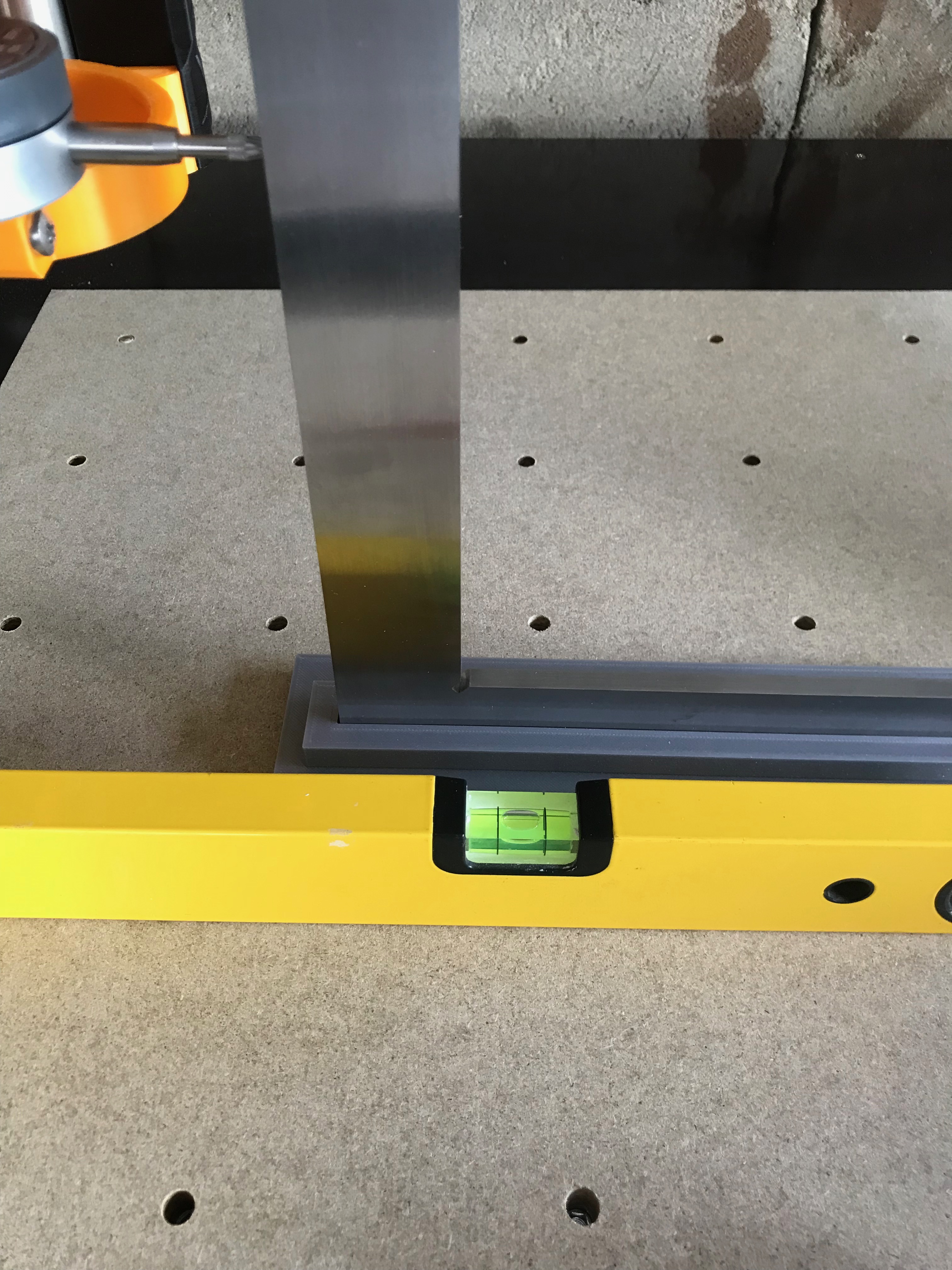
I was building my first MPCNC primo and spent a lot of time for squaring the frame. After the build was done, I did the last adjustments: correcting values for stepper motors (x and y was just 2/100 mm to short, z was perfect), horizontal leveling the frame and so on. At the end, I wanted to adjust my spindle, in order to get them as straight as possible over the workpiece. I was measuring with a clock and a measuring angle (dont know if you guys know about DIN, its maybe more a german thing… but DIN 870-0 its an almost perfect 90 degree angle for measuring and calibration purposes). The angle is on top of a perfectly aligned surface. If im measuring the z axis over a range of 200 mm, I got a deviation of roughly about 1.7 mm. Thats way to much. How can I do any adjustments for the spindle? Are there some screws to get it perfectly aligned?
I made a short video of my measurement:
“youtu.be/H1xqrSr1heM”
The typical way to handle the deviation is to first surface your spoil board using a large (sometimes called "surfacing) bit. This will make sure that the surface is parallel to the XY plane of your CNC. Then you want to use a tramming arm (like this one) and shim your router to get it perpendicular to the spoilboard. There are a couple of tramming arms on Thingiverse, but they are easy to make out of a piece of wood. Because of the way they work, the tramming arm can be pretty rough with the holes out of alignment, and the results will still be accurate.
But with this said, the wisdom of the forum is that it is usually beneficial to ignore this deviation at first until you have some hours with your machine. This will shake out any mechanical issues with the machine and will give you experience with feed and speeds, helping you set up a good surfacing of the spoil board. There are lots of kinds of toolpaths that can handle some deviation.
Hi Robert,
but how can i get a perpendicular router? the tramming arm is just to see if the router is perpedicular or not. are there any screws that i need to tighten, to change the angle?
There are no screws. The way mentioned on this forum (and the way I used on my Burly) was to shim inside the motor mount between the mount and the router. I created my shims from cutting up a cat food can. A small bit of shimming makes a larger difference in angle. But right now you don’t know if you need shimming or not. I did not need it with my Primo. Given manufacturing imperfections in MDF, and construction imperfections in the MPCNC , you don’t know if you have a tramming issue yet. You have to surface the spoil board to create the two parallel planes before you can test for the angle using a tramming arm.
One is the Z rails themselves. Adjustment here isn’t easy, but there is a little bit which can be adjusted in the core clamps, by means of tension on the bearings. If your printer is square and true, this should be minimal, but there is some adjustment possible to the X travel to make it square to the X and Y planes. On initial assembly, my Z axis was as close to perfect as I could ask for in the YZ plane, and just a bit off on the XZ. About 1/16 turn on the outside bearing on one of the core clamps brought it to square.
After that, the Z axis travel was square, but the router was still sitting off true on the YZ. In that case, looked at the bolts that attached the router holder to the Z axis tubes, and tightened one of them about a half turn more than they were. I guess there was a little space in between the tool holder and the V1 backing plate. Not so much that you’d notice it, but it was enough to let the tool be out of true by just enough.
For motion, all 3 axes of my machine were dead on, but the tool diameters seems to be undersized. Though nominally 1/8" bits, mine cut almost exactly a 3mm kerf. I get tabs and slots that work “sand to fit” with a defined tool diameter of 3.04mm instead of the nominal 3.18.