I’m dying over here. ![]()

4 Likes
That looks very effective. At least, a lot more effective than me, just watching them grow and hoping for the best.
2 Likes
That works!
1 Like
You have got this thing stuck in my head.
Planetary gears, fit the steppers in the “wheels”, is way faster better for a yank, or is slow and super strong better…so many questions and ideas.
2 Likes
Definitely this, because fast yank will snap the stems and then you still have the roots in. Especially when pulling out oak seeds with this long ass single root, yanking does not work, believe me, I know… Those damn oaks…
2 Likes
So now how are you going to attach them to your boots? ![]()
2 Likes
Curious if people prefer JST/Dupont connectors, screw terminals or some other no solder wire to PCB solution? For screw terminals, feel like 3.5mm or larger pitch are more fun to use (18 to 22AWG).
- JST/DuPont terminal like JackPot and SKR
- Screw Terminal
- WAGO wire to PCB terminal connector
- Some other wire to PCB connector?
0
voters
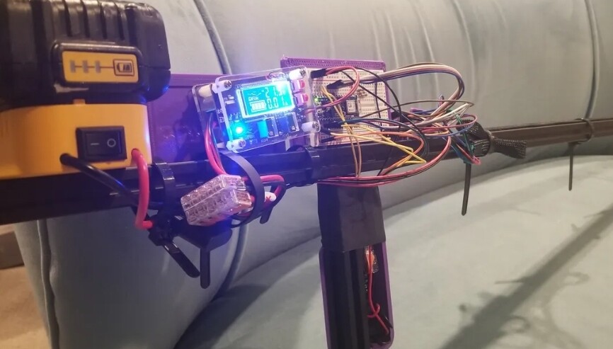
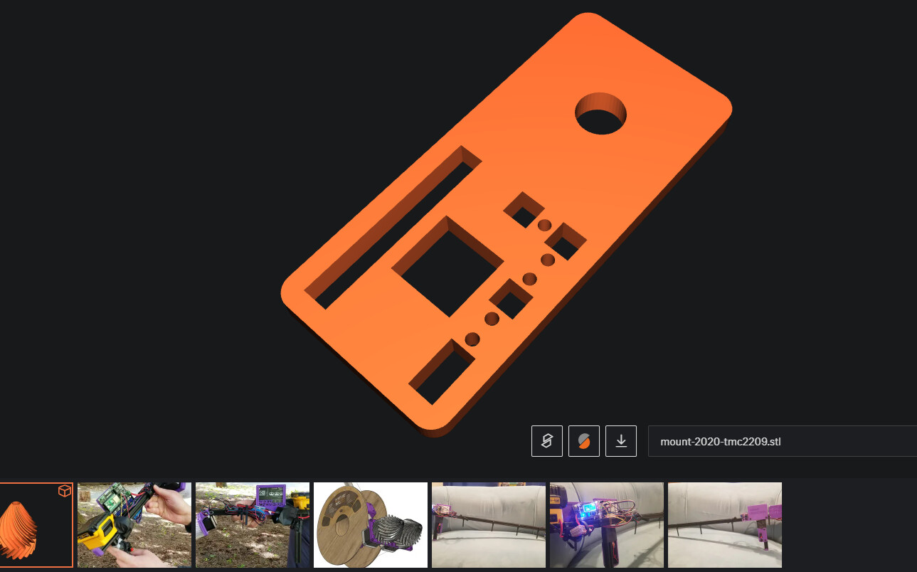
Current wiring setup is ![]()
![]() . So, I’d like to do better and try remixing/making a PCB with just the essentials for a WiFi/Bluetooth enabled questionable semi-auto weeder…
. So, I’d like to do better and try remixing/making a PCB with just the essentials for a WiFi/Bluetooth enabled questionable semi-auto weeder…
tl;dr: Pluggable screw terminals, bootlace ferrules, ferrule crimper, good quality wire strippers, correctly sized technician’s screwdriver. Done.
Depends on the application and what your needs are. Everything has it’s place.
Pluggable screw terminals are my strong preference for DIY/prototyping purposes. Specifically screw terminals with a rising cage clamp and using bootlace ferrules on stranded wire. That way you’ve got the flexibility of screw terminals for doing field wiring, testing, adjusting things over time etc. but also the convenience of being able to unplug the wiring harness from the circuit boards. They’re available in a range of sizes but the 3.81mm/0.15" pitch ones are my preference for robustness and not being ‘too’ bulky. Works for everything from reasonably small signal up to mains and power distribution. There’s a de-facto standard for these where most companies make something cross-compatible. The ones I use are Wurth Elektronic ones but there are TE, Molex, Phoenix Contact variants or plenty of options from the usual Chinese suppliers. The 2.54mm/0.1" pitch ones are too small and cross back over into being inconvenient vs other options. I’ve also not noticed a huge difference in quality between genuine ones and unbranded/knock off ones. Not enough to make me 100% decided on one vs the other, at least. I use housings from a Chinese brand that come with specially made 5.08mm pitch terminals to suit the housings, for instance.
Wagos are great for industrial/cabinet wiring type situations where they may need to be modified but not removed wholesale and won’t necessarily be exposed to as much mechanical stress/strain as other solutions. Also good for wire-to-wire, but that’s not the question here.
Crimp terminals when it comes to production, although very much not Dupont. The world has moved on. I would go with something that has a shape that prevents misalignment during mating, ideally a full or at least partial housing on the header and ideally some form of retention clip. Also receptacles with multiple sliding contact surfaces, not just a single one. JST (actually a company, I can’t remember which exact product that usually refers to) are fine, as are most of the products I’ve seen from them. I’m a big fan of the Molex Mini-Fit series or TE Micro Mate-N-Lok. That’s what I use in some of my products. The genuine ones are decently priced but you can get knock-offs. They’re a bit bulky but there are other similar products stepping down and down in size. The smallest I’ve used recently is the Molex Picoblade which is great but fiddly to use. The single biggest thing with crimp terminals is that there is a MUCH wider range in quality for the crimps themselves as well as the tooling between genuine and knock-off, as well as a huge random range in quality from Chinese suppliers. Some people have zero issues, some people can never get a reliable crimp because the dies are deformed. It pays to know what to look for and have a plan for how you’ll QC the crimps themselves, even just by careful inspection and pulling a few to failure. The field-application crimp tools I have are between $400 and $800 each and wouldn’t really be considered good enough for production. We’d be getting production wiring made externally by a company using semi or fully automated presses.
Edit:
Some other thoughts:
These are the things I mean for pluggable screw terminals:
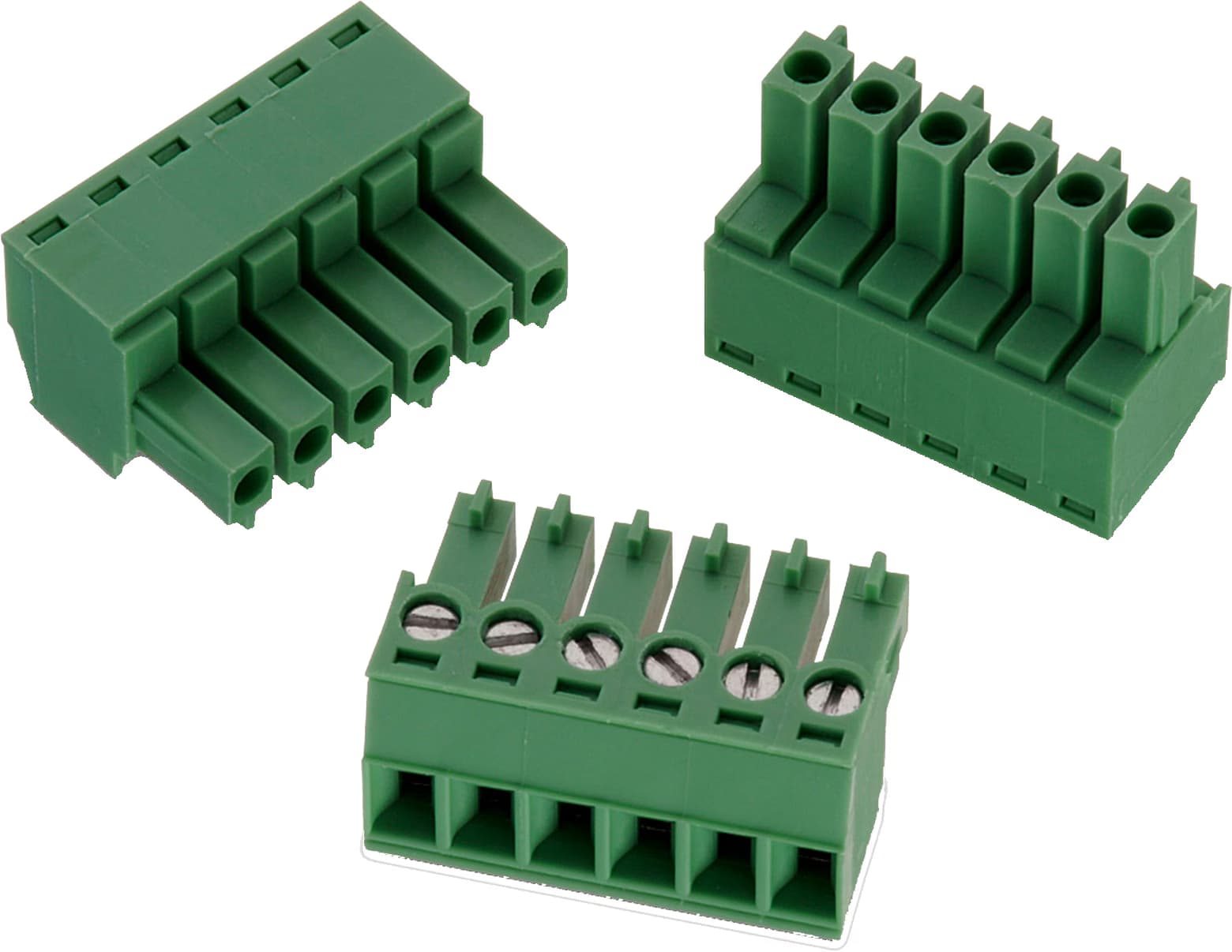
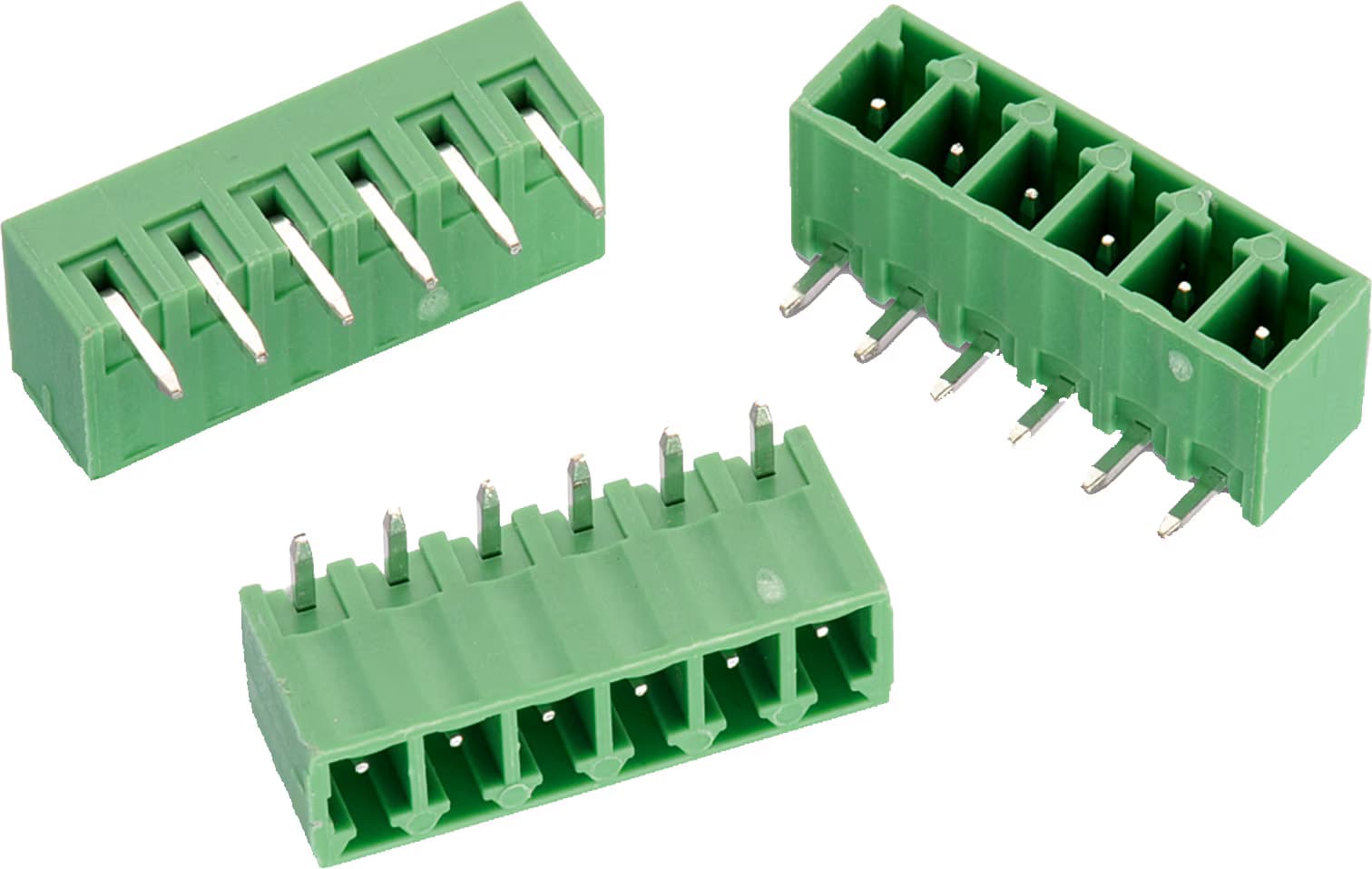
That’s the combo I’d use most often. I default to using the horizontal PCB headers at the edge of a board and then use vertical PCB headers if I don’t have space off the board at the edges or need something in the middle. I almost exclusively use the ‘vertical’ style of plug where the cable exit is in line with the mating direction, although there are styles that come out at an angle or at right angles which could be useful in the right situation. With well fitted through-holes in the board I’ve never had any robustness issues with these and the right-angle ones are somewhat inspectable on the backside for proper solder flow through the barrel. For extreme environments you can get versions that have the header mechanically secured to the PCB with screws/pins and others where the plug screws into the header. I’ve never found an issue and think that in general those are better handled with strain relief on the wire and other design features etc. For me that has proven fine even in heavy industrial/automotive environments.
Having a good quality set of semi-automatic wire strippers is super helpful, as is a good ergonomic ferrule crimper. Get a range of ferrules that suit the wire size (don’t mix and match). Getting ones that are also the correct length for the screw terminals is nice, but you can easily trim them with side cutters if you’re not doing hundreds. I think for the 3.81mm pluggable screw terminals I end up with 6mm ferrules instead of the more common 8 or 10mm ones.
Wire stripper - https://www.digikey.co.nz/en/products/detail/phoenix-contact/1212150/2553355
That’s what I use at home. There are tons of companies that make similar ones and while some are nicer than others, I’ve not run into any that are ‘bad’. I’d avoid the ones that are like that but at ‘right angles’, or the ones that are like old-school electricians ones like this:
https://www.digikey.co.nz/en/products/detail/klein-tools-inc/11063W/6804883
Ferrule Crimper -
Self adjusting ones are cool and convenient but a bit of a luxury. Any set that fits well and has the jaws close tightly should be fine, it’s not a super high precision situation. The ones I’ve got from a previous job are Phoenix Contact self adjusting ones but they’re in the $300-400 range so definitely ridiculous for most situations. The main thing is making sure they work well down to the sizes used as some (looking at a Klein set) are clearly more towards electricians and only go down to 22AWG. I’d say down to 24AWG would be better, although they’re probably still work on smaller stuff well enough for DIY cases. Whatever the case, I’d look for ones that crimp to square or trapezoid rather than hex, personally.
4 Likes
Yeah, using a breadboard, amzn ESP32 breakout board and TPU based Driver scrote mounts are a great way to make rats nest controllers… Hoping to make a less fluffed up custom PCB with custom firmware setup (2-3 steppers + misc sensors) after I get stall detection working more reliably. Am not planning to run fluidnc/gcode on this thing.
Started with a JackPot, tried Arduino Nano on breadboard just because, currently… Going back to ESP32 on a breakout, before custom PCB. Can’t mount stock TMC2209 breakouts onto breadboard, so, this was my good enough solution…

2 Likes
what firmware are you customizing or are you rolling your own?
Rolling my own, or at least trying to… There isn’t much code. Stepper config and control via UART has been straight forward, except for StallGuard… Am unable to reliably trigger stall Diag pin when a step is missed, am resorting to sampling EMF in rolling window and kinda guessing, can only detect bad stall happened. Good enough for this silly project, but feels dirty and inadequate for more precise motion control. Guessing my understanding of StallGuard is still lacking. Am not adding position encoder(s) for this project, but would for future precise things.
EDIT: FFS, spent more time on StallGuard Diag than I’ll admit, then, shortly after writing this post, I get it working after removing a bunch of setup/config stuff. PITA, but works much less bad now.
From what I’ve seen for StallGuard, it’s rather particular and probably not well suited for what you would be trying to do. It still seems to be best suited for sensorless homing and that is still finicky.
1 Like
ok then… Steppers 've been trying are stalling too easily. Was hoping they’d be good enough to minimize parts. So, am trying couple of StepperOnline planetary gears, but they’re pricey and the dimensions are not great.
Anyone have affordable 3:1 to 5:1 Planetary gears they like using? Looking for metal, but am open to 3D printing some as well for comparison sake, if only to see how quickly they get destroyed.
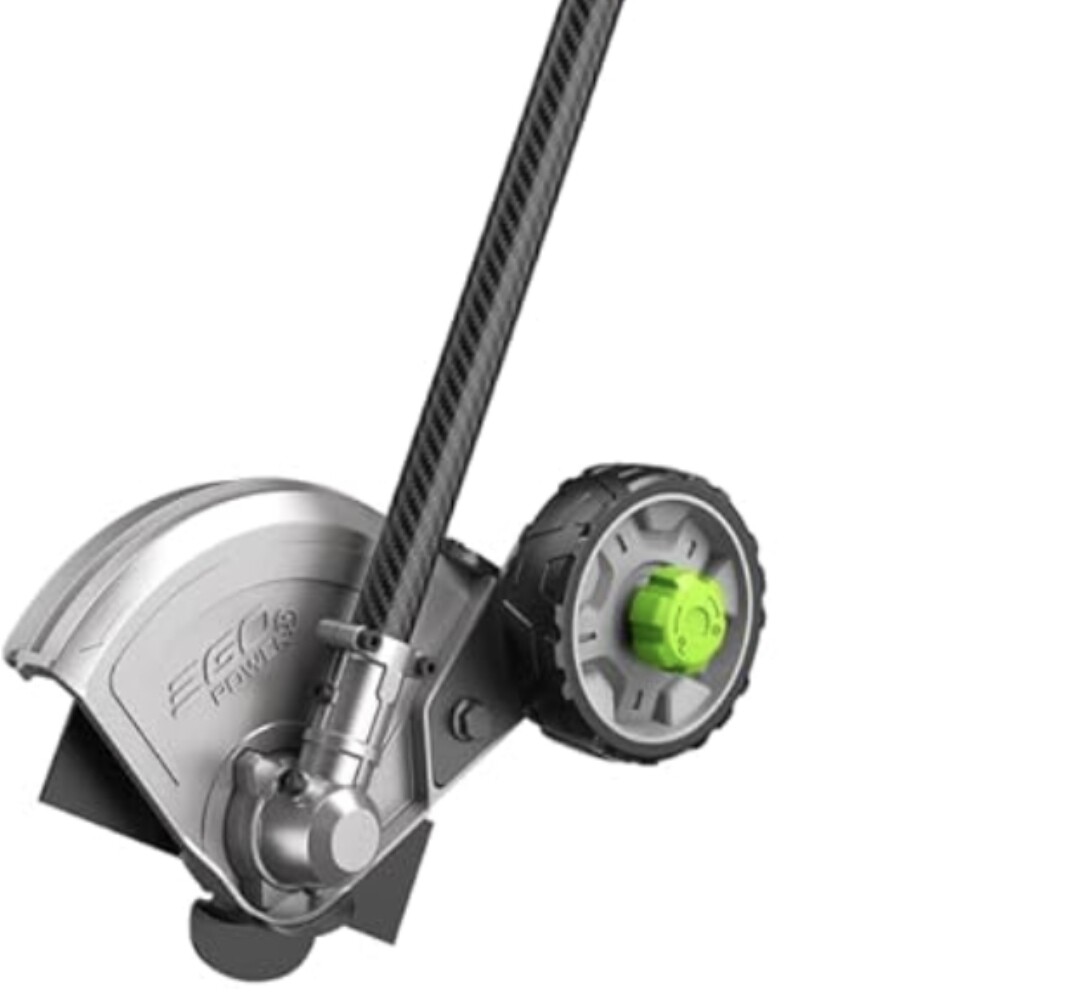
Left: Previous grinder, Center: Updated grinder, Right: Father’s Day edition grinder…

1 Like
How many pins are you actually using off of the board?
Can I be the odd man out and say use a soldered on DB9 connector with the screw terminal to help keep it from vibrating off?
1 Like
There are a couple of decent NEMA17 sized planetary gearboxes on thingiverse and printables.
Not in a spot where i can pass links today but maybe late today or tomorrow I will have a chance
1 Like
Thanks @MakerJim, agree, there’s some neat printable Planetary Gearbox designs out there. Look forward to trying out a couple after I figure out what’s possible with the metal ones, and some less messy wiring.
That could be cool. Personally have a special place in my heart for DB9 connectors having spent many years fiddling with Commodore 64 and Amigas.
Arduino (v0.2) and ESP32 (v0.3) version ended wire up like this, and just as messy IRL…
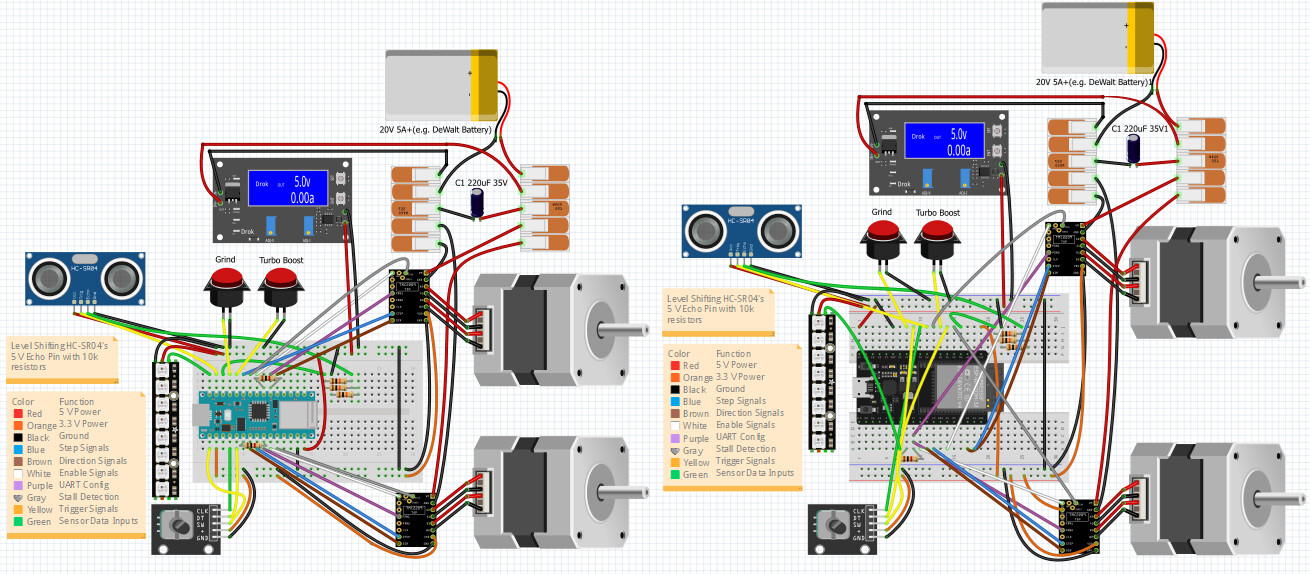
Was neat getting my initial JackPot (v0.1) prototype experiment running, was relatively fast to configure FluidNC. But JackPot’s overkill for this silly tool, so, I will loosely rationalize this project as an opportunity to try making a smaller slimmer pcb with 2-4 steppers, “SidePot” ?
Maybe also consider simply smaller diameter? Like if you had tall cones, the tips would have higher force and could also reach closer to the root. Maybe a shield/floor so it doesn’t pull itself into the ground and lift up dirt
1 Like
There’s smaller Nema 23 options, but they’re way heavier than I expected ![]()
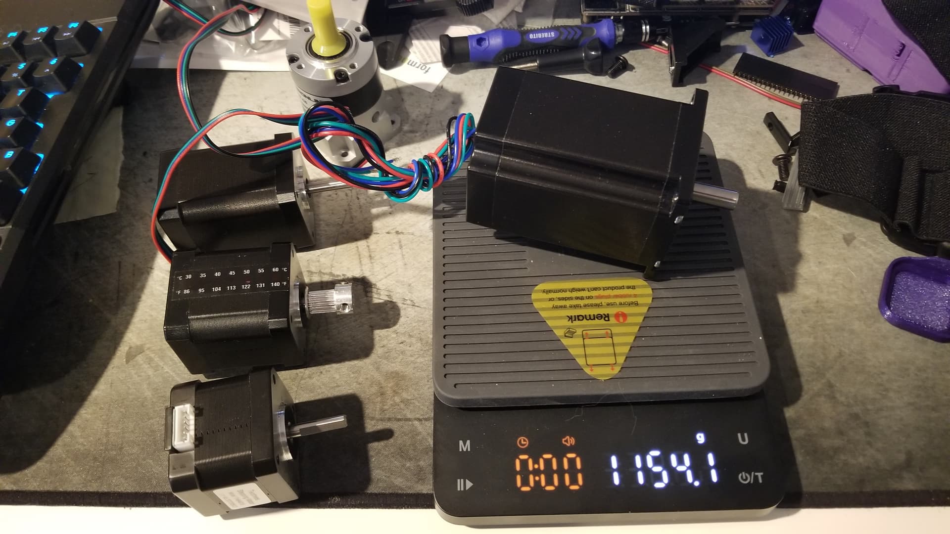
Looking at geared brushed/brushless motors…
1 Like