It is definitely a price hike, going from $2 a meter to $3.22 per foot from one supplier I use for closed belts
When building, I thought about, but never tested the effect belt tension had on the linear accuracy of X and Y movements. We built it, tensioned the X & Y belts so they didn’t shake too much in operation (4x8 ft working bed area, ~5x9 ft actual bed size), and started making parts. Is there a spec? Since we have not used any quantitative method to measure belt tension, I couldn’t tell you what our tension is even if we had a spec. Has anyone looked at the pitch change with belt tension?
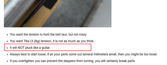
Yes it is listed in the instructions, 7lbs. Once you get past 3-4 lbs I doubt there will be any change. The belt overall does have some stretch but tension just makes for premature wear, not a longer belt.
No, luckily we can not stretch into place. When we see more test numbers here I hope to prove that. The numbers for the belts from me should all be very consistent and the tension from each user will be all over the place.
If tension mattered too much we would be in trouble for lots of reasons.
*belts are fiber lined, not just rubber, so the fiberglass or Kevlar fibers should not allow for any stretch.
so does this belt “feature” answer the MP3DP v5 periodic structure question? @Michael_Melancon
I’m not sure.
I changed just about everything on mine to try to get rid of it.
I use different belts now, but I also saw it some with the different belts as well.
I haven’t noticed it as much lately, but haven’t printed much with large flat sides.
I did print the LR4 braces and didn’t notice any ripple there, though. It’s really hit and miss when it decides to show itself.
I am thinking out loud here, as 3-7 lbs seems to be quite some leeway, yet the less prescriptive the instructions are there is a corresponding lack of clarity, particularly for someone unfamiliar with how a belt works.
We have a lot of human resource here, (and I have a lot of projects and no digital strain gauge or scale), but would it possible to create a collaborative project, to determine either pitch (like Prusa does) or measure with a belt tension meter.
It seems to me to be an almost trivial thing to take a 2.4m belt, stretch it correctly, measure, then to account for an infinite number of build sizes, repeat at even 100mm increments, although I suspect 250mm will be OK, then create a table based on average results from those who particpated.
Is there a flaw in this logic?
The 'audio tuning" method works really well - and there are a ton of free apps which can read the pitch.
If there’s a pitch, it might be too tight ![]()
I honestly struggled with this with my LR3 build because I had no idea about any of it…
My belts were waaaay looser on my LR3 than on my printer.
Since the precise tuning doesn’t matter as much, maybe what would help is just a short video that says “This is roughly what it should feel like/look like/sound like”, etc
The range is so great it really doesn’t matter, but if you wanted to know for sure you can put a scale on the back of the Y belt blocks and give it a pull to see exactly what 7 lbs feels like, and adjust the tension screw if it moves.
The audio thing, is not as easy as it sounds, we all played with that on our V5’s and it is pretty solidly hot or miss and about 5x more tension that I would ever put on a CNC. I am actually pretty convinced some sites are reporting the wrong audio tuning specs. I have not seen prusa’s guide, but I am pretty sure they also still use a 6mm belt.
Tension has always been hard to quantify without a gauge. I can make a sell a gauge but anyone else that makes one would not be the same as mine. There is a 3D printed gauge with some sort of standard wire, I forget what they use now, but it could work. I just never felt like it was very necessary.
I think it is a piano wire or something.
I have one. The “suggested numbers” that are out there are usually for 6mm belt, from what I’ve found. I had to set my numbers a bit higher I believe to match the correct tension by lbs of force. I think I documented somewhere the numbers I got per lb of tension using a fish scale… I’d have to dig that out somewhere
If you give a meter for people to print themselves, then the springs have to be consistent for everyone or you’ll get slightly different numbers.
Maybe I can see if we have our tension meter.
This whole talk reminds me of the old dc3 elevator cable tension story.
Big long run of cables that if you tension at a warm temp say 40 deg c and then you fly up to an elevated cool airport or at altitude. And the cables are very loose when the structure (aluminum contracts ) in the cold.
Iirc and it’s been probably 20 years but we used to tension alternator belts on the Navajos simply by using a ruler 1/2” flex at the mid span.
This might be something that could be built into the belt and conduit calculator. Like if you have a full size table the correct tension should be at mid span 3” deflection with a 7lb pull on a fish scale. Idk
I think some of this might only be for the temp controlled large table guys a manual read out. does seem like a good quick check but some form of go no go guage could work.
Like your two spot check. But maybe with a counter sink.
That ruler method could actually be a pretty good one, you would need a ruler and a scale.
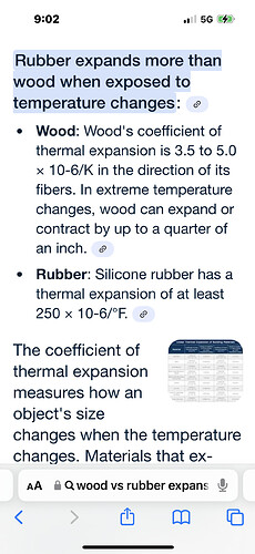
The belts are fiber lined so temp should not play a big role unless you are the extremes.
If someone has a fancy tension tester setting the tension to 7-9lbs and checking how far off you are would be great. I a very confident the best way is just test along your longest axis with a no load dot or poke and set both axis the the correct offset. I doubt tension is going to have much effect at all.
I think this is a good thing to discover there can be manufacturing variations in the belts.
When I first put my LR3 together I did notice some significant variation in my cut lengths vs. CAD lengths. But to be fair my belts were too loose initially and after I tightened the Y belts evenly it got rid of the majority of variation I was seeing. To the point that I think there is hardly any CAD to cut length error. I guess the point I am making is any minor error due to belt variation seems secondary to having the belts too loose.
To now think it is possible to tune my machine even further. ![]() So I am happy to follow the proposed extra calibration step.
So I am happy to follow the proposed extra calibration step.
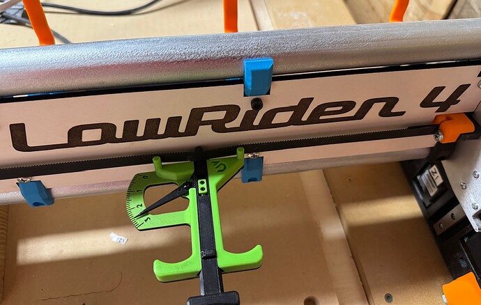
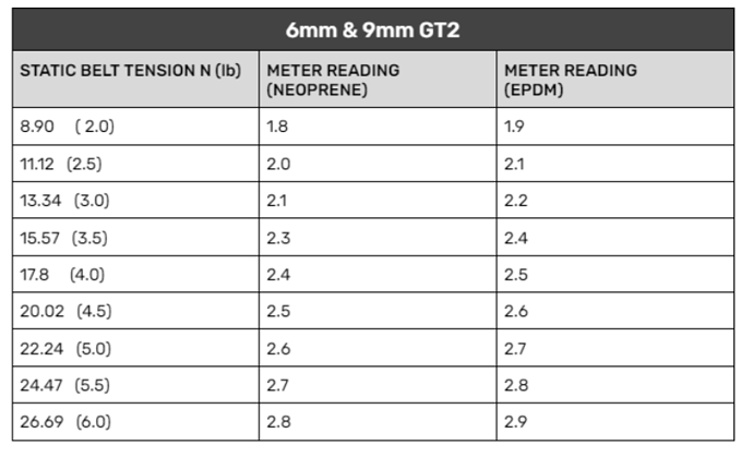
I just printed the tensiometer from West 3D. Looks like it has the range to handle the relatively low tension of the Lowrider belts (There are charts that roughly convert it to tension.) The piano wire is used to adjust the tension on the spring. It was a reasonably easy print. Its a little fiddly, but I needed it for a problem with my printer (in a twist of fate I did actually need to tighten the belts which I usually try to leave at the lower end of the spec.)
When I do convert my LR3, I can try to use the device on the belts and report back.
I have a tension gauge coming as well.
I got an official one I bought when I built my V5
This seems about how I was running my LR3.
According to the chart, that’s ~4.5lbs
Nice tool ![]()
Ok, so now that I have my Y belts back running, I tested again, and that setting seemed a bit loose on Y.
I now have it right at 2.9-3.0, which should be in that 6-7 lbs range.
This feels “tight enough” and roughly equivalent to where I was running my LR3
ohhh, sounds like someone might be making some test cuts soon???
I decided to revert to the 50.0 setting after I realized:
- my 48" X axis is actually dead on (hole poking test) after all, with my lr2 era belt, as far as I can measure with my tape measure.
- With 50.73 setting, jogging 100 mm increments on my fluid dial would end up with weird rounding issues like displaying 99.99 after jogging. This was the biggest annoyance that made me revert.
- A test cut of a 100x100 mm circle seemed as accurate as I could measure with my calipers, within about 0.05 mm or better, so close enough for the next project…
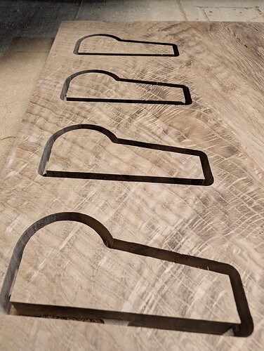
(some craftsman furniture, will post when it’s done!)
will need to bookmark this thread for my next test, i did wonder about steps per mm as i have to do this with the 3d printer
