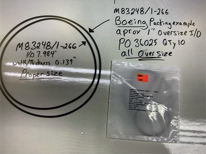
SWEEEEEEEEET!!! ![]()
Just curious if they have any batch or cure dates ?
That’s how we track our defective things.
Should also let the vender know as well.
It says Boeing, so don’t pretend you wouldn’t still use it whether it fits or not… ![]()
Don’t get me started on that company lol. Mc Donnell Douglass dudes messed that all up.
But at least the vender can track it down to a batch defect and correct it.
None I can see to report back to them,
Absolutely.
Possible data point: I seem to have my belts from my LR2, apparently I didn’t use my belts I ordered for the LR3 (“PowGE” markings.) Same steppers and gears.
With my LR4, measuring grid lines I engraved, the 1200mm seems to be actually 1198 on the Y axis assuming my tape measure is accurate. I verified the X axis engraving is off by about 2 mm, so it seems consistent? It’s MDF so slightly “blurry” but definitely a wee bit short. I will do a more precise check if there’s a change suggested.
Same jackpot etc as my LR3, so this isn’t new I guess. Just never noticed!
The older (lr2) and newer (lr3) belts I have seem to mesh identically when pressed together, but only checked on a short section. I didn’t order any belts for lr4, mine are all “old”
It’s my understanding that @Jonathjon likes to buy 1km worth of belt with each order. ![]()
I came across this issue back when I was building my Primo. I ended up changing the values and was able to dial it in very quickly using a long steel ruler and cleaning pick.
I decided to make the change because the X & Y values were off by the same amount, and I thought it was related to part and assembly tolerances. Just like feeds and speeds are build specific, I thought steps/mm would be the same.
I probably would have been fine not doing it but I just wanted to minimize the chance for any potential issues down the road.
How I calibrated my machine for possible belt stretch: tape a shiny, long, quality metal ruler down to the spoilboard, parallel to the axis being adjusted. Fix a very sharp needle into the spindle (make sure it is not bent).
Move the Z so that the needle is pretty close to the mm marks on the ruler.
Set (0,0) at the ruler’s origin.
Command a movement to nearly the full length of the ruler.
By aligning the needle’s reflection on the ruler with the real needle you can eliminate any parallax error. Sight with one eye, to measure how far it actually went. You can get accurate to about 100um with this method if you are careful. For my 600mm ruler, that is one part in 6,000.
Adjust the Steps per MM in the firmware and repeat the measurement. My numbers were only about 0.1% off.
Be wary of any backlash in the system: You should approach the origin from the negative side to start, and then continue in that same direction to make your measurement.
You can also use this setup to measure how bad your backlash is in X and Y.
LOL I used to order extra every time worrying about it. Now I just get whatever comes in the kit ![]()
I wound up with 100.1 to get my parts close to as designed sizing, was able to see it with a dial indicator over 1" in a couple places (some spots were closer than others to what was commanded).
No this is a very bad way to calibrate.
There are so many things that add up to an actual part’s size. Error stack up, runn out, slop, flex, temperature, bit sharpness, bit accuracy. This is a no no that I will be watching out for in any calibration posts.
I strongly recommend you do the two marked dots test. From there your parts calibration is all done in CAM, never step calibration. Two marks test your machine under zero load, while cutting load and flex will vary drastically.
Feedback on belts. I’m sure there are better ways to measure this, but here’s some quick and dirty information.
My machine is 30 x 60, so my movements needed to be in that range.
First - My spoilboard plan (on Sunday, September 18, 2022) included a grid, along which I burned a pattern for a metric ruler.
To compare when the belts were new, and starting at 100, 100 (Its due to laser offset):
Moving 500 mm on X (Its pretty close, parallax is showing it off more than true):
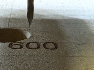
Moving 1200 on Y (It is visibly short.)

And moving 500 X against my metric tape measure (parallax makes the x move look more short that true, estimate 1 mm) :
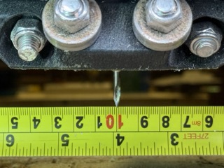
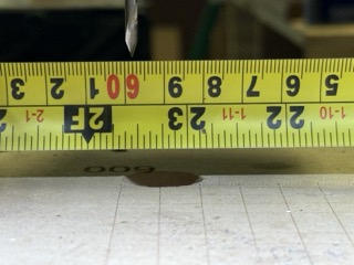
Moving 1100 Y against the tape measure (estimate 1.5 mm short):
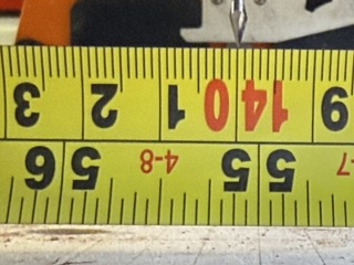
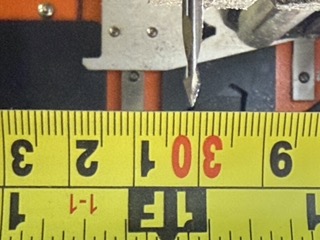
Hope the data is helpful in some way. It feels like there’s been a little stretch perhaps due to the number of times I’ve removed the X-belt to service the machine. But the machine does appear to be moving short when compared to the tape measure. (0.2% in X, 0.14% in Y)
Its interesting that Y moves visibly short of the pattern burned 14 months ago.
I’ve been happy with it.
Awesome thank you.
This is interesting. Hoping the difference is just measurement error. Since we are off by so little and error on a smaller measurement is compounded more. I do like seeing the same 0.14%
I have been thinking about this alot.
Now start chasing 0.18 mm with the delrin rack&pinion each turn…
Based on the part alone, yes I agree, that’s why I moved to measuring travel with a dial indicator in multiple spots because I noticed the machine was not moving as much as it should have been (undersized external AND internal features). Some parts of the belt is actually sized as it is supposed to be (1.000" commanded = 1.000" of movement), most spots I wound up with less than 1" of movement per 1" commanded hence my adjustment.
Are you using my belt or did you get your own?
If you are only moving one inch 0.00146" is a tough one to measure.
Yours from my Primo, and .0015 is pretty easy to see on an indicator. Wasn’t always .0015 short, like +/- .001" variation on that from what I remember, was a while ago. Those belts have turned out quite a few good parts out of aluminum since.
That is a bummer, if you got them that long ago they were most certainly from a differnt supplier.
If your change was less than a year ago, would be likely then. Unfortunately with gates belts 10mm width is a non-standard width, 9mm and 12mm being “standard”.
9 is fine, but the price is not.
