So this is an ongoing project, but the Lowrider2 - pingpong build Has been indispensable, and I’m seriously impressed with todays efforts so I just had to share progress to date!
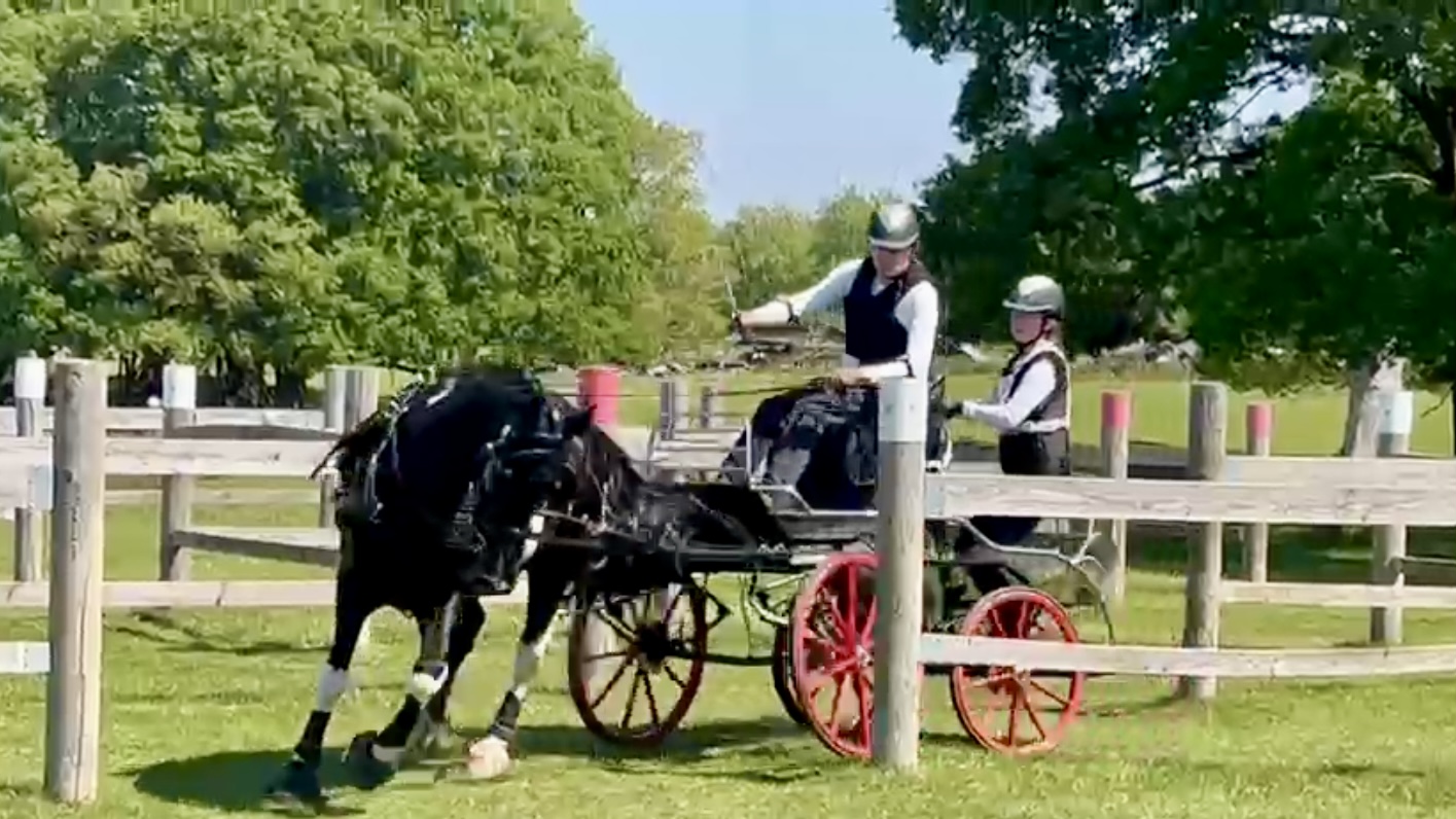
A bit of background, I compete in an equestrian sport called horse driving trials (known as combined driving events in the US). It’s like ridden 3 -day eventing, but we drive the horse from the carriage towed behind it. The carriage essentially a 4-wheel turntable trailer. The front axle moves with the horse, and is mounted under a ball bearing turntable, above which the body (to which rear axle is attached) is mounted. It is a feat of engineering itself with front and rear disc brakes, and a delayed steering system that means that when the horse turns in a competition obstacle, the carriage behind doesnt cut in and hit the post on the inside of the turn.
On slippery ground the back end of the carriage can “oversteer” or drift out, which can cause stability issues, so the competitive (expensive) carriages have a brake system on the turntable or 5th wheel, which we can preload to increase resistance to the back end stepping out, or to mash a foot pedal lock it on when everything gets sideways! My carriage, 23years old and while still good, does not have this system, but we are getting more competitive and the horse has more than enough power to make a turntable brake a must-have for next competition season.
I reached out to a guy I know who builds and modifies carriages to ask how much to add one - he came back with a quote of £1000! I don’t have £1000, but im a mechanical engineer, with solidworks, a lowrider2, and a stubbonness to achieve that usually gets me where I’m going. I’ve always thought the systems were overpriced, so Ive set a budget of £200 for the full system, to include pedal, custom 1/2 circle brake disc, calliper mounting bracket, and custom pretensioner system. Really the cost doesn’t matter, but it would be nice
First job was to measure up the carriage and model the turntable area.
Then find a brake calliper… we run MX bike hydraulic callipers on the wheels, but I found a mechanical calliper (golf cart work brake) on Ali-express (£18 posted!) the T-T brake, as havent got space or budget for another master cylinder.
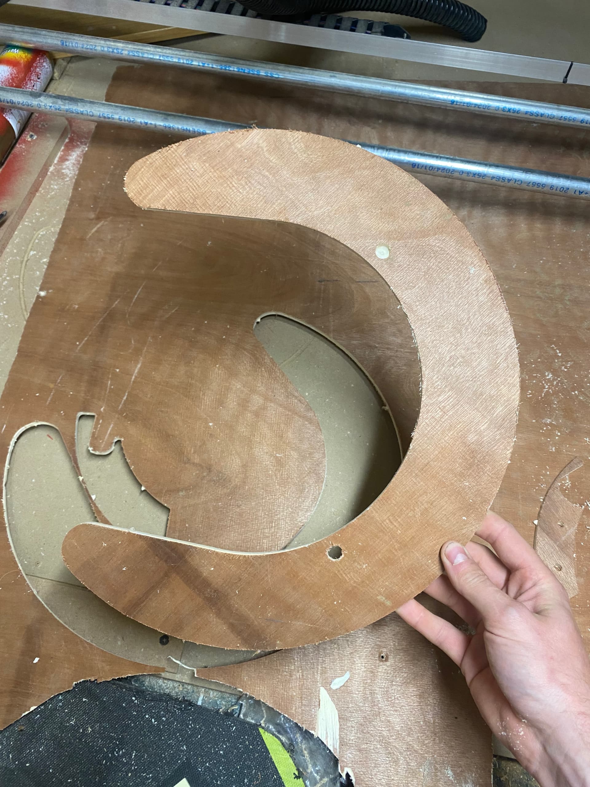
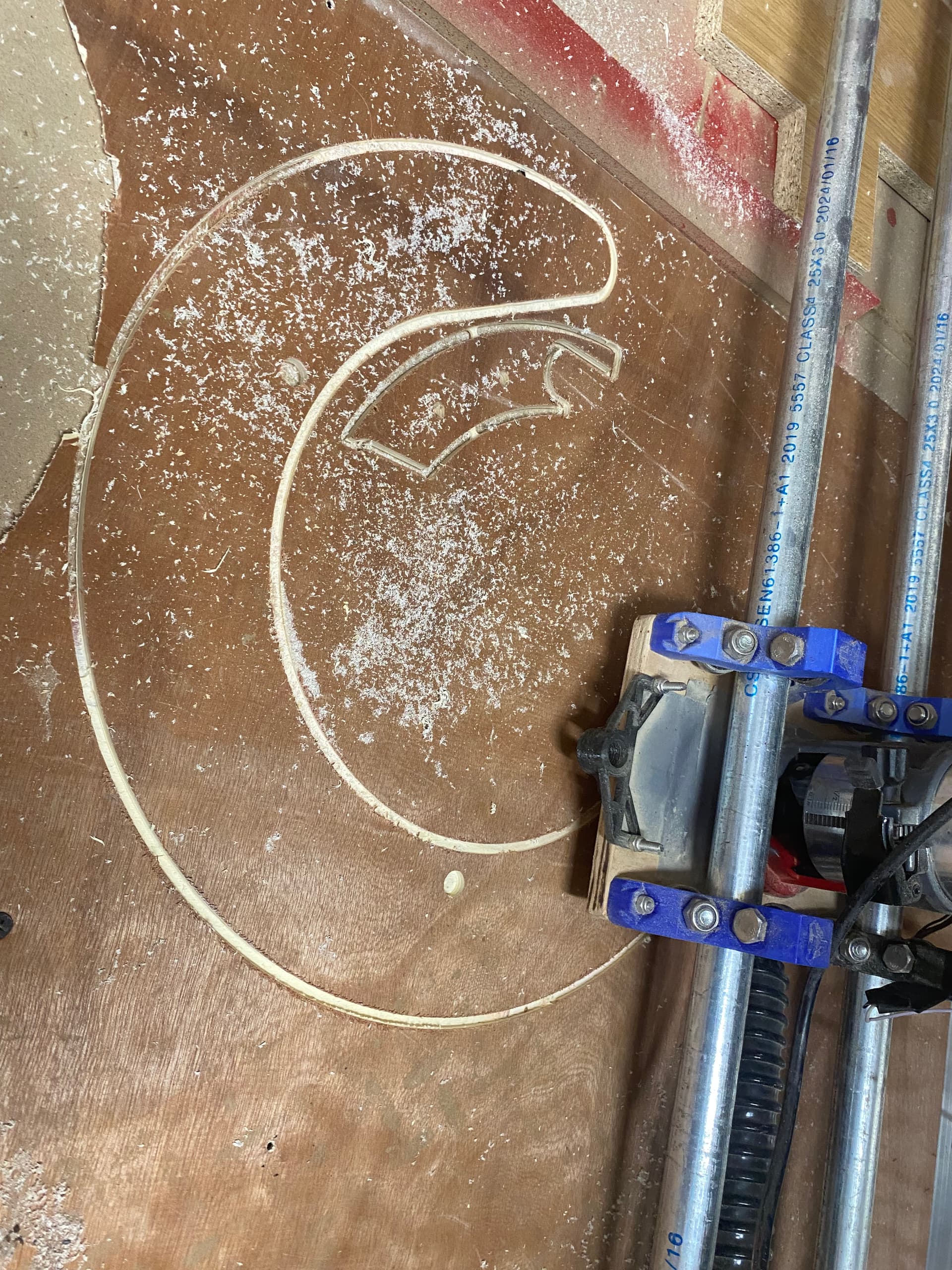
From there I could design a custom brake disc to bolt onto the lower half of the turntable (front axle side). The front axle only turns approx 160 degrees under the turntable, so a full disc isnt required (adding lightness, a la Colin Chapman of Lotus Fame). After 3 iterations in 6mm ply I had something that aligned and missed the turntable grease nipples etc.
I could then start designing the calliper mounting bracket to pickup on existing holes and locate the calliper on a place that picked up on the brake disc without fouling anything as the fore carriage turns relative to the body.
The lowrider was indispensable here as could make new templates quickly in mdf to test fit. The final bracket will be aluminium (sent-cut-send or equivalent) but I wanted to make sure that the CAD was right before committing. There were a few variations including one in EVA stockboard which was the first time milling a plastic.

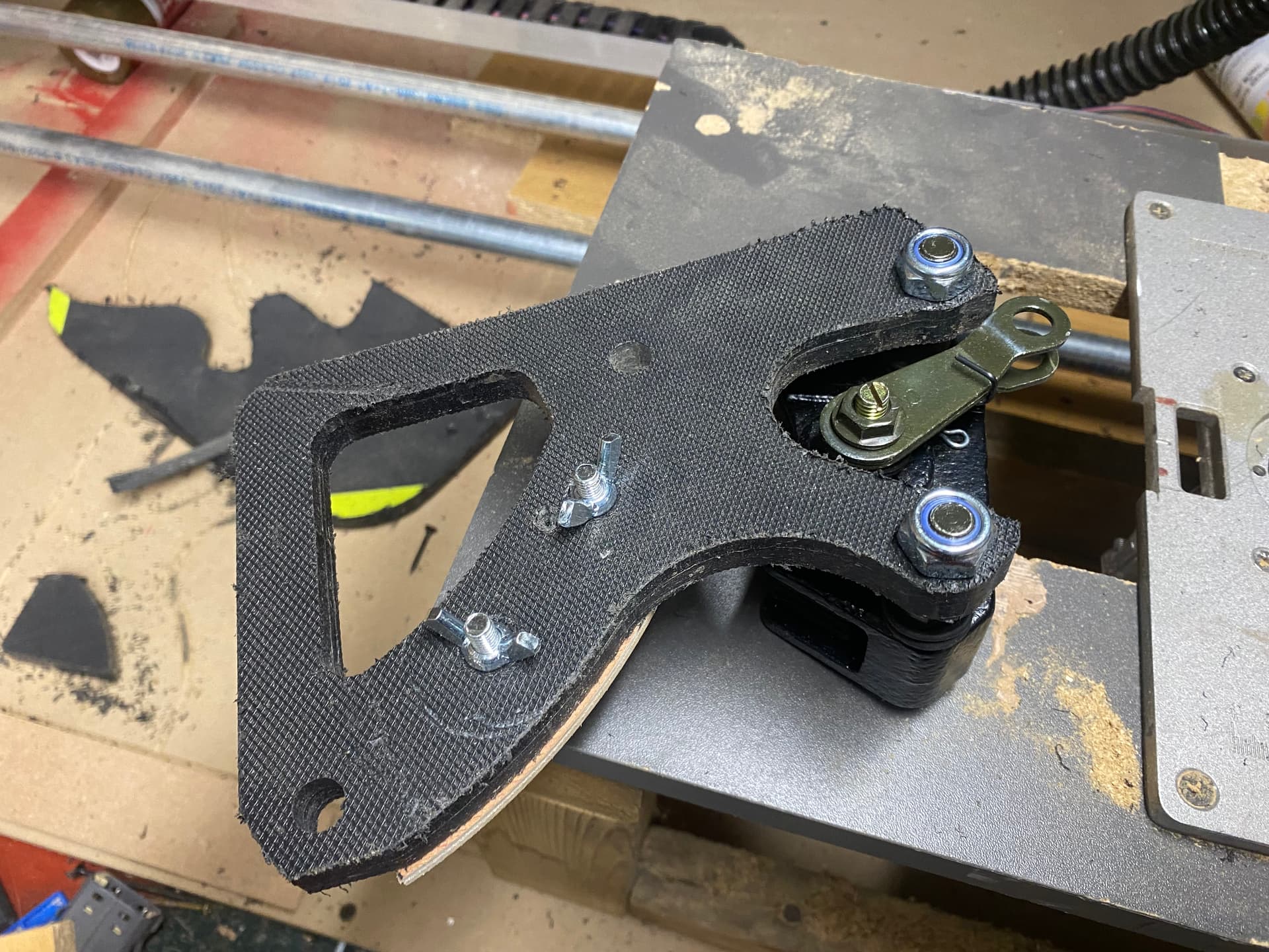
With the shape right I needed to account for some pockets required, and to create a boss through which the cable could pass and restrain the outer sheaving - cue more modelling in solidworks (I learnt it at uni, and now pay for the hobby licence). Eventually I had a design I was happy with, and so set about sorting the gcode in estlcam.
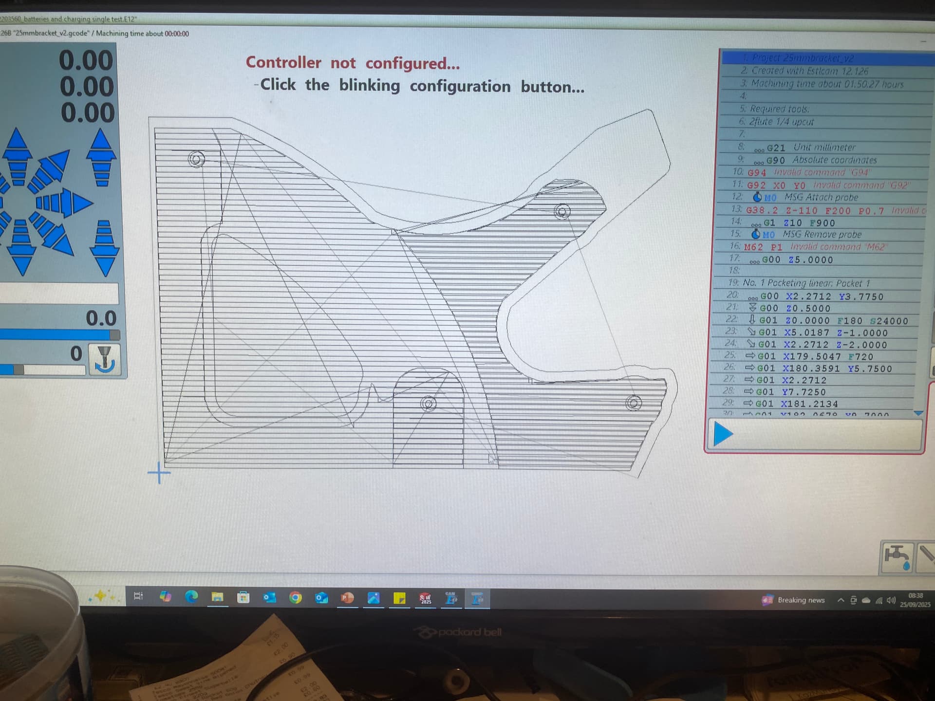
I have a l-shape fence setup at my origin on the machine, so for efficient material usage I do a lot of edge engraving to part-off the finished item, but it turns out my pocketing strategy needs more work as could see I was wasting time in the way I removed material. overall part depth is 25mm and I wanted it to be strong enough to actually mount as a test piece so I went for LDPE as a prototype, it cut really well but I did manage to block my dust extraction by putting a paper template on top of the workpiece held in place with double sided tape - caused a gumball of plastic chips in the pipe! Dust extractor is a 30mm flex pipe attached to a whole house wall mounted 1000w vacuum cleaner, so clogging is a thing, I have several short lengths of pipe joined by 3d printed couplers which make clearing the affected area easy with a long stick.
Because of a 25mm cut requirement, I ended up using a 1/4 50mm 2flute upcut, wow that thing it’s loud. I don’t have 1/8 collet yet, but would be worried about deflection.
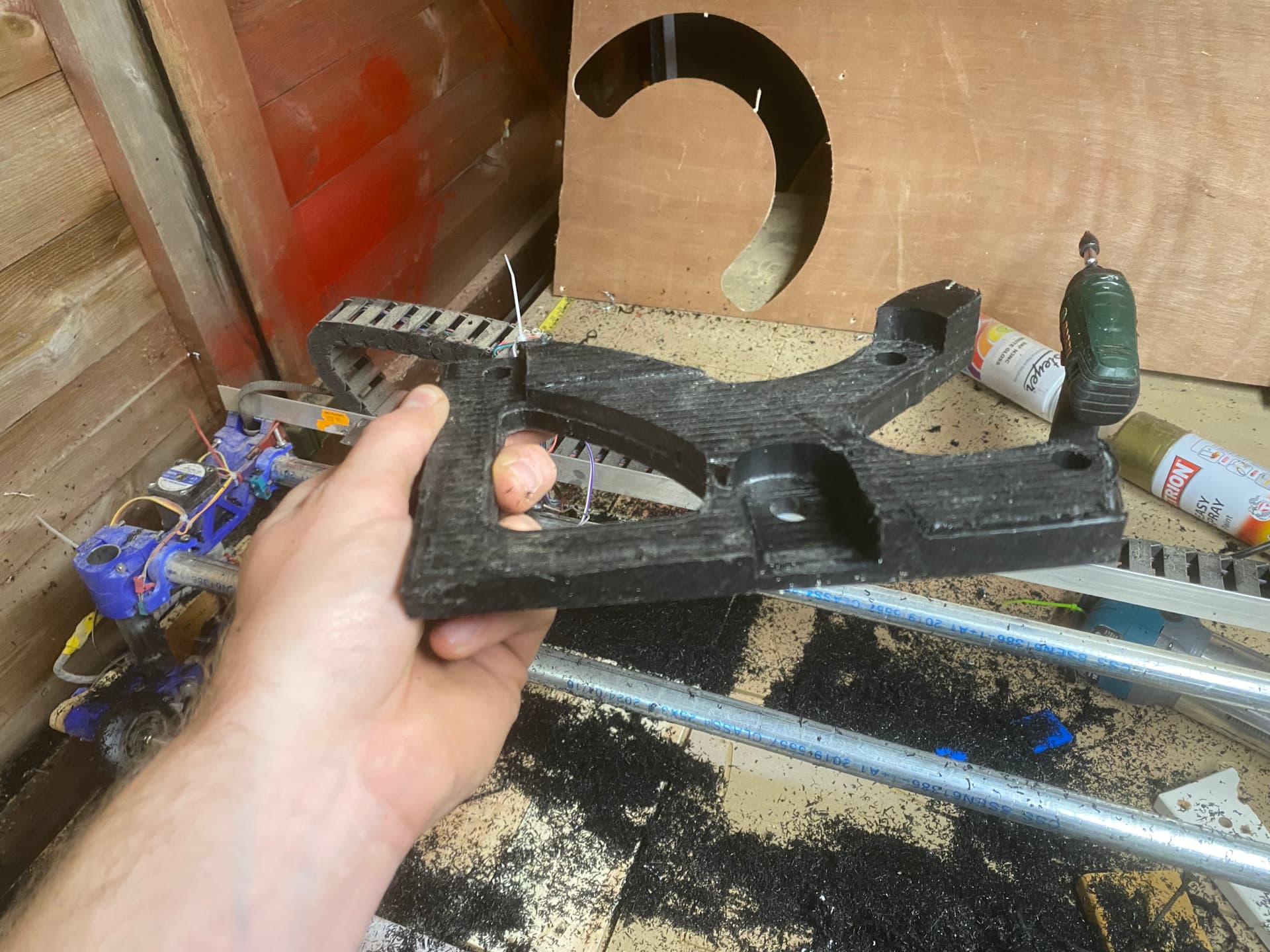
Ive been stacked out with events and a house renovation since July when I got the gcode finished but today was the day. My table is anything but level (saggy old pingpong table) but I have put on a second mini spoilboard which I have surface for for a work job which gave me a flat (enough) basis to mount this bracket job to.
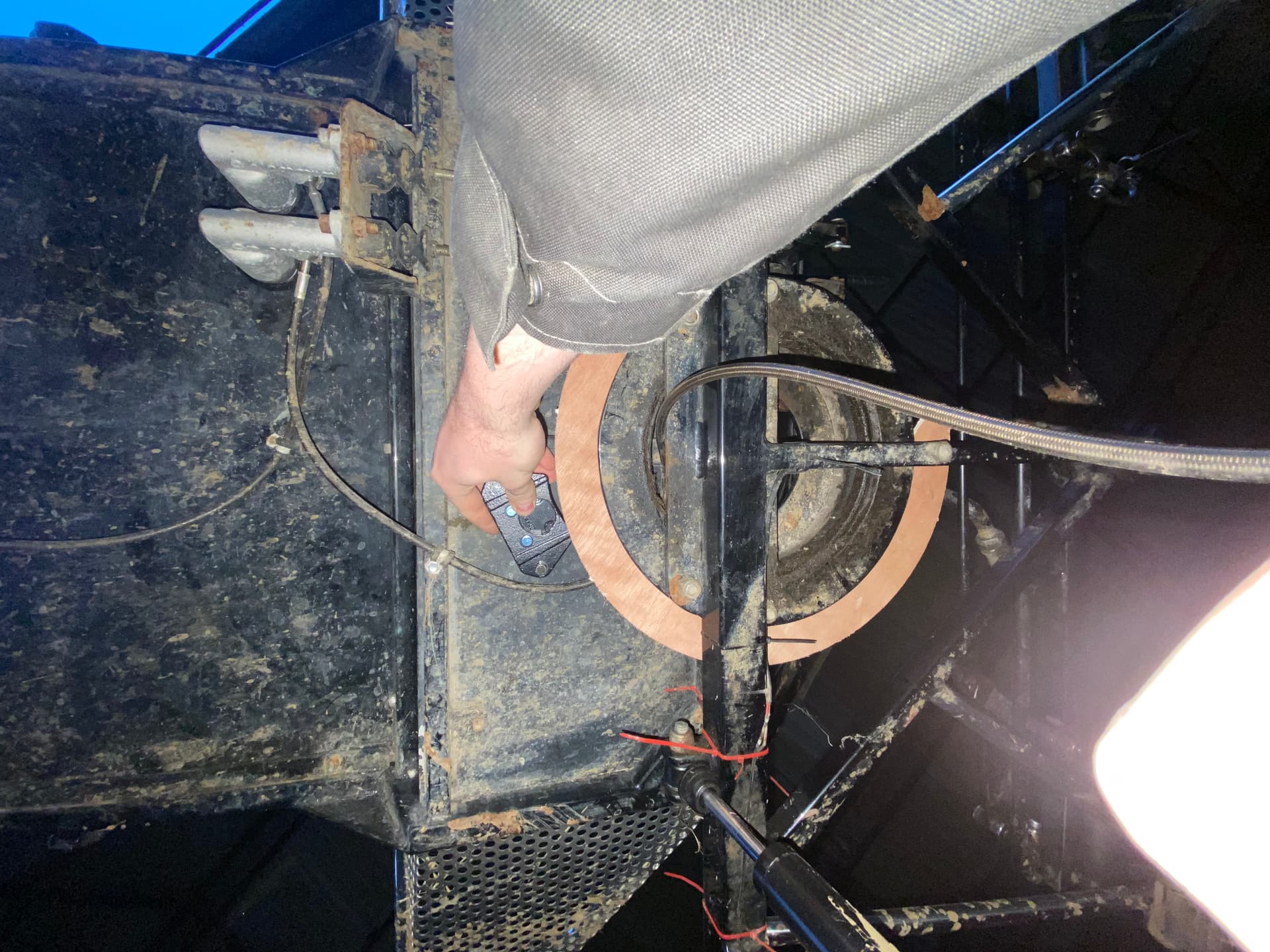
I am so so pleased with how the part came out! Definitely could benefit from better feeds and speeds, but this is rough prototyping, so can clean up any swarf etc after. The part is surprisingly solid, so it may make it to the actual function test phase, provided it fits!!
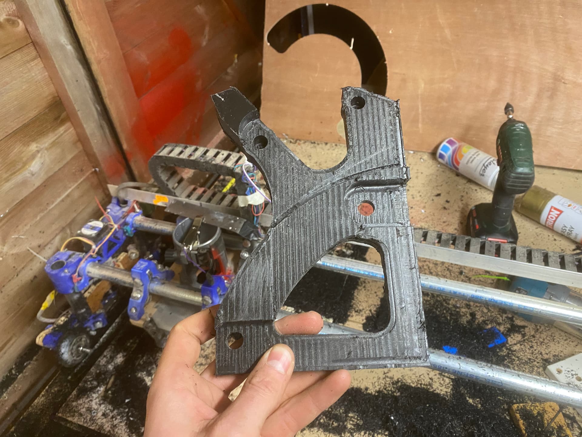
Will test fit today and report back, but in the meantime all I can say is a massive thank you to Ryan and everyone on the forum for their support and assistance with my oversize build and for being the inspiration to try this project in the first place!