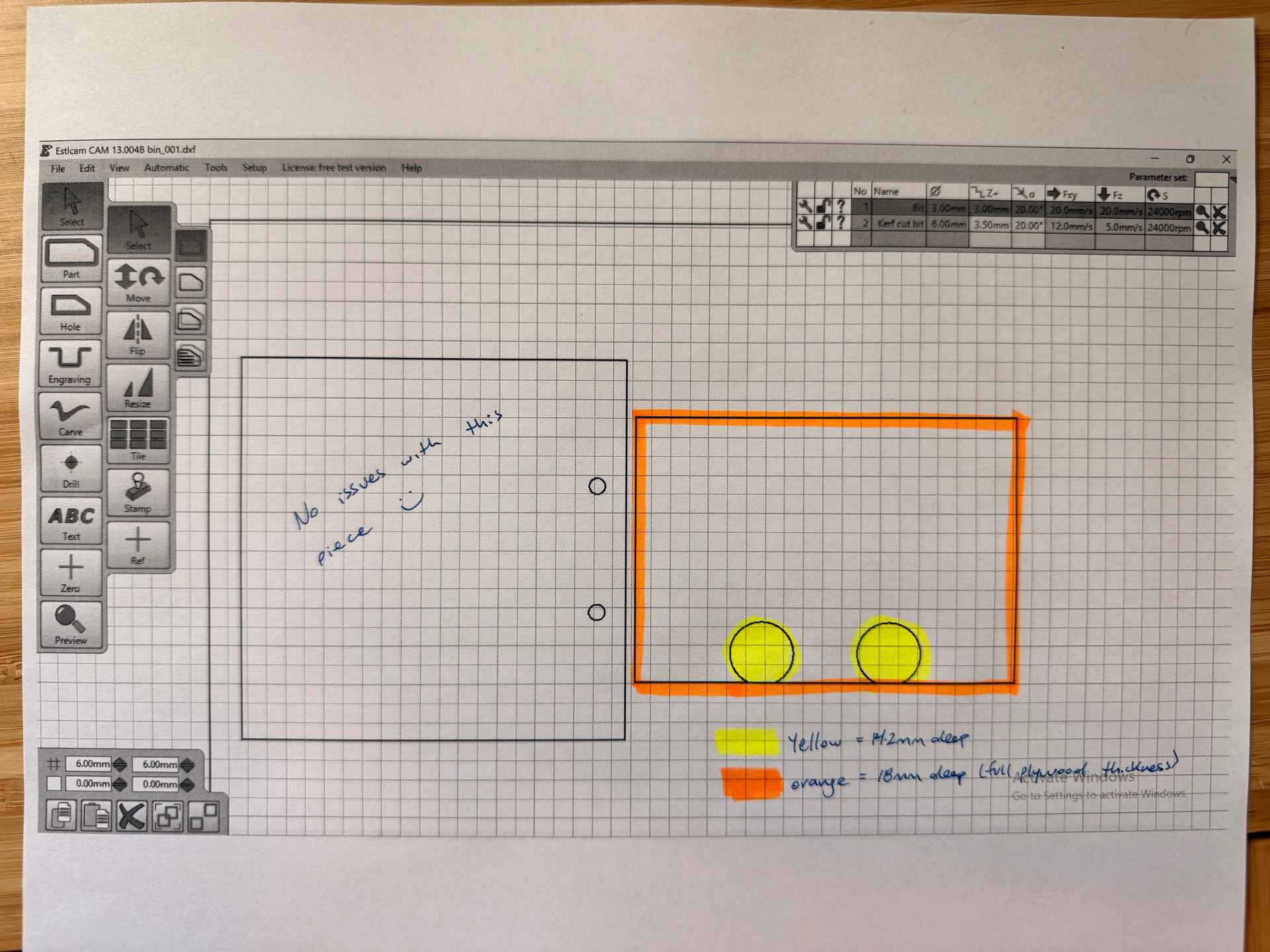
Hello, I’m setting up tool paths in Estlcam to use Hafele Rafix 20 connectors. Some of the machining that’s required is milling a 20mm diameter blind hole partway through the material (I’m using 18mm plywood, and the blind hole is 14.2mm deep). The blind hole is not a perfect circle, but rather a “D” shape.
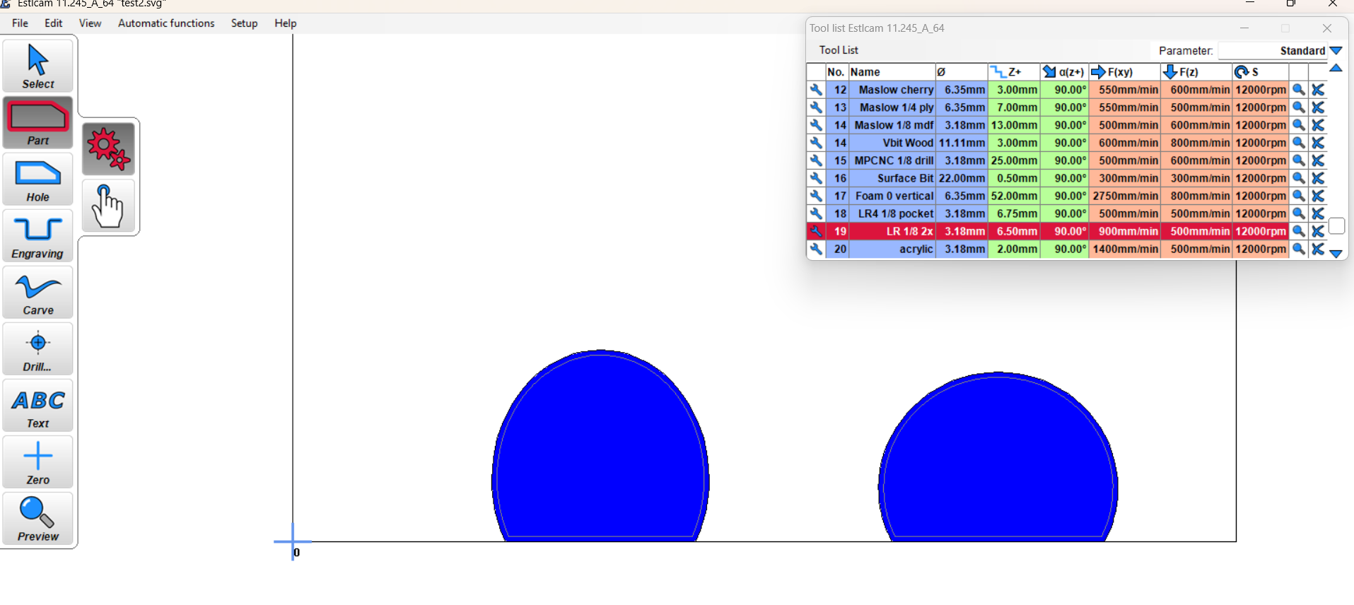
Could you please provide guidance on how I can mill the two 20mm blind holes (yellow in the image below) at a shallower depth than the rest of the piece (orange in the image below)?
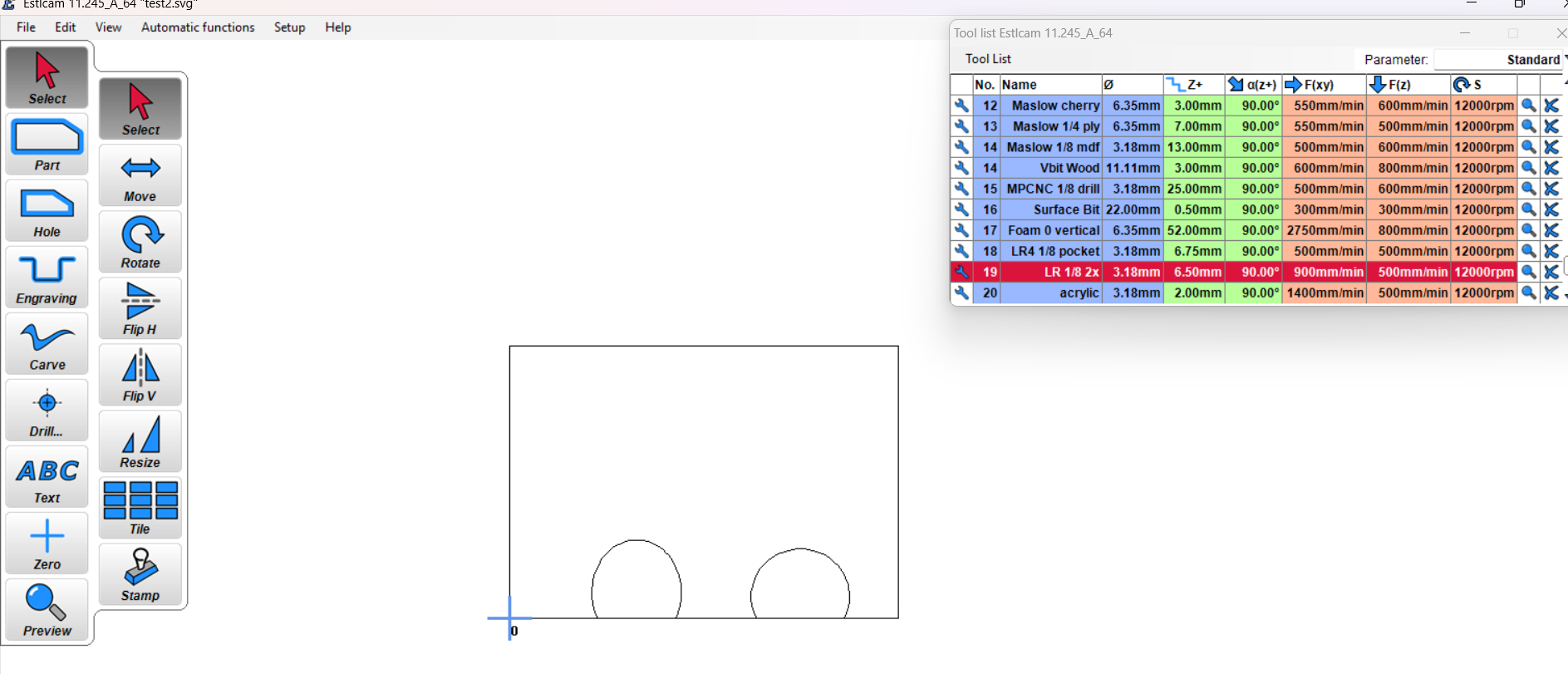
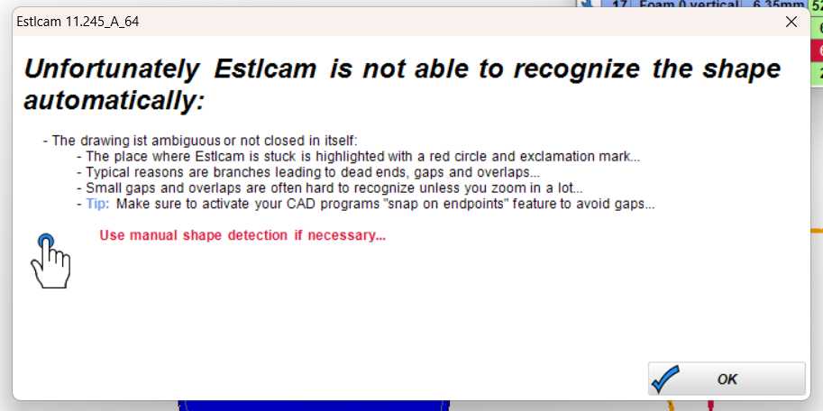
Click on your yellow-marked feature (one of the circles). If the shape is not joined, then you may need to use the trace tool, which is to the right of the hole tool with the finger and the dot.
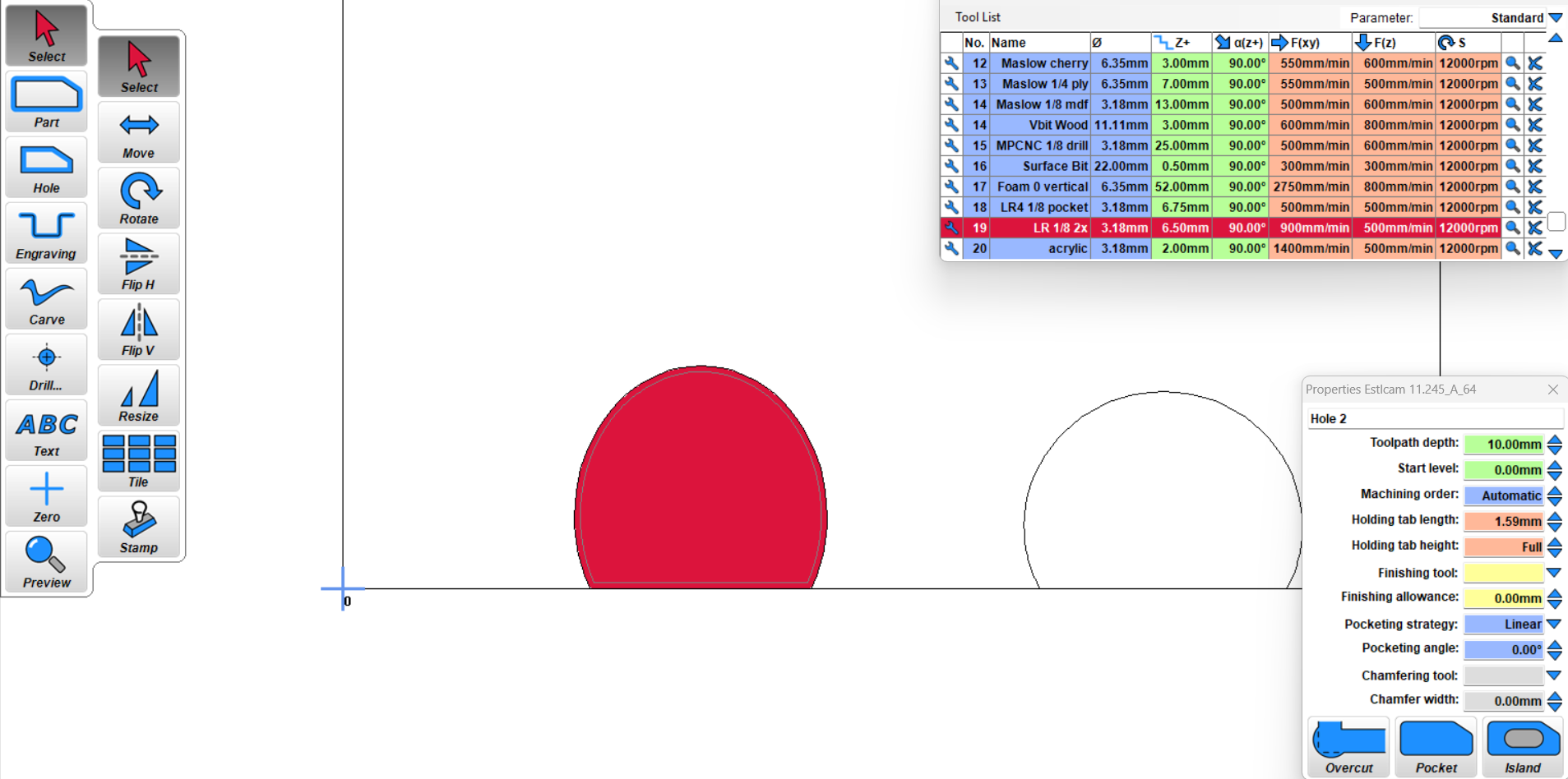
click on the circle somewhere and then move your mouse around the circle and Right click to have it follow the curve. The circle should be highlighted with the red cut mark on the inside of the circle. If you wanted to cut outside it, you would use the part tool.
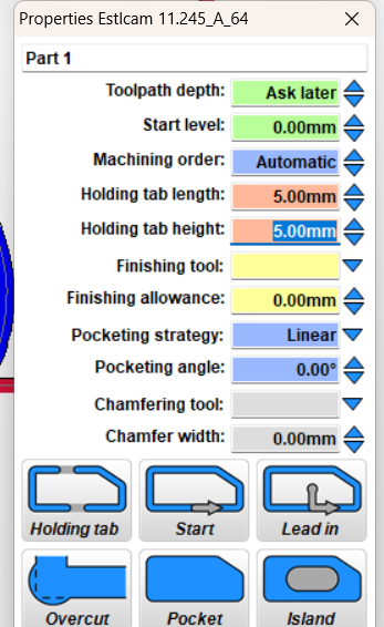
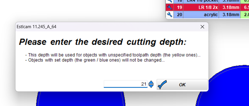
In lower right click pocket option and manually set toolpath depth. Repeat for the second yellow part.
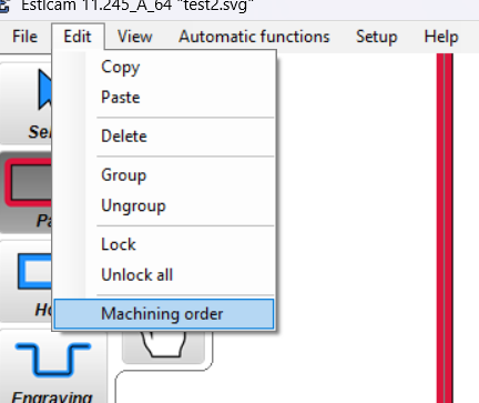
For another perspective. I start with Create objects automatically whenever I can. I try to set path properties in the order that I want to machine them. Path properties always includes a meaningful (group) name (visible in Preview and G-code), machining priority, Depth and whatever else is appropriate (e.g. a finishing allowance and tool… and tabs, my bad). Note: A bug in v12 ( Dave Lers : Workshop : CNC : Estlcam : v12 : Issues ) makes group naming a PITA (one of the reasons I mostly use v11).
You guys are amazing. Many thanks for spending the time to provide such thorough feedback. I’m at work still today and out of town this weekend but I’m confident I’ll be able to get it going with this guidance when I return next week!