Does this indicate twist in my gantry, and if so what is the best way to address it?
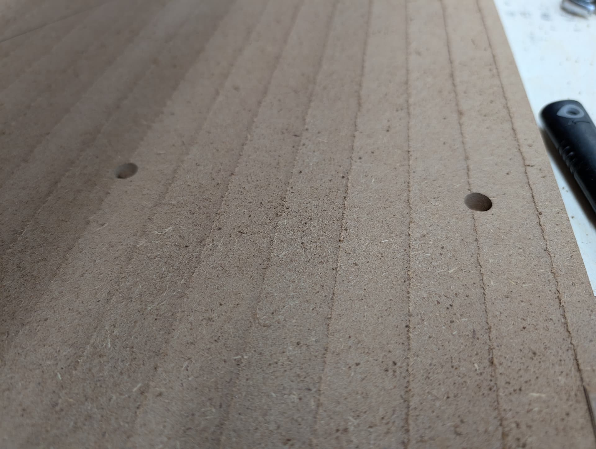
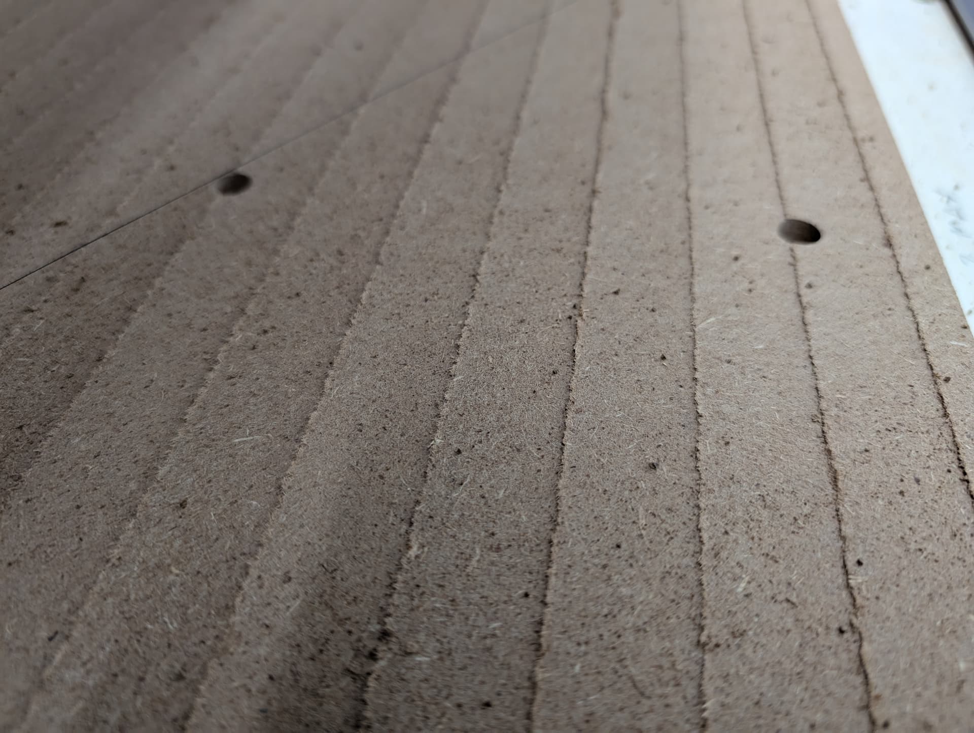
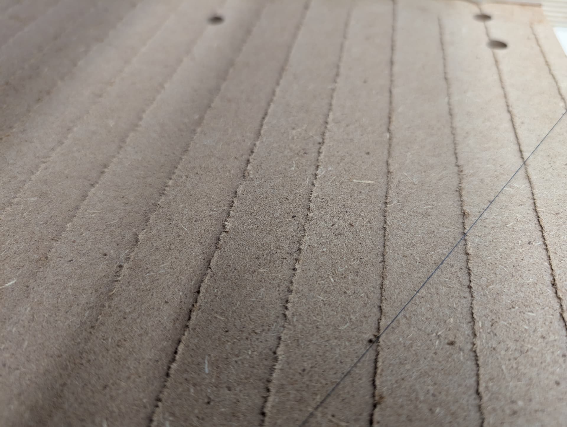
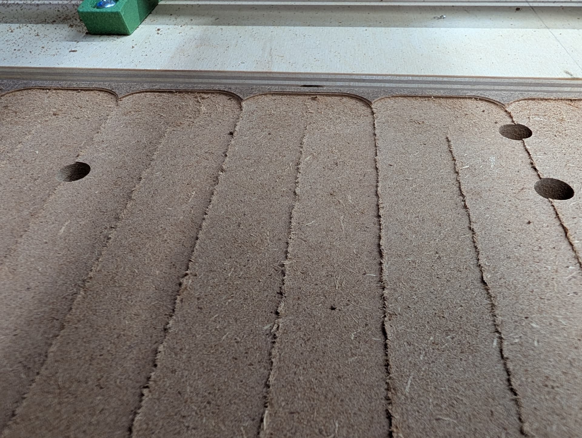
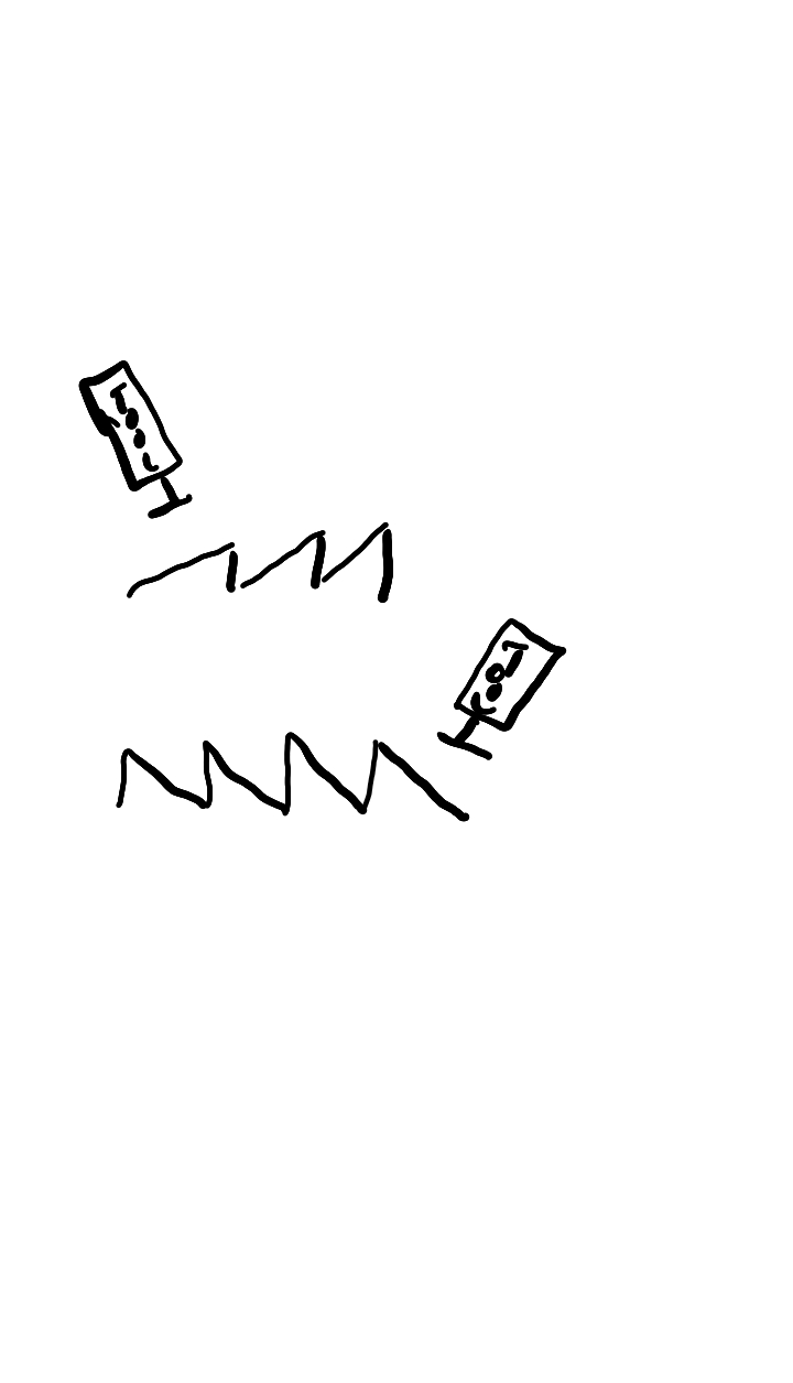
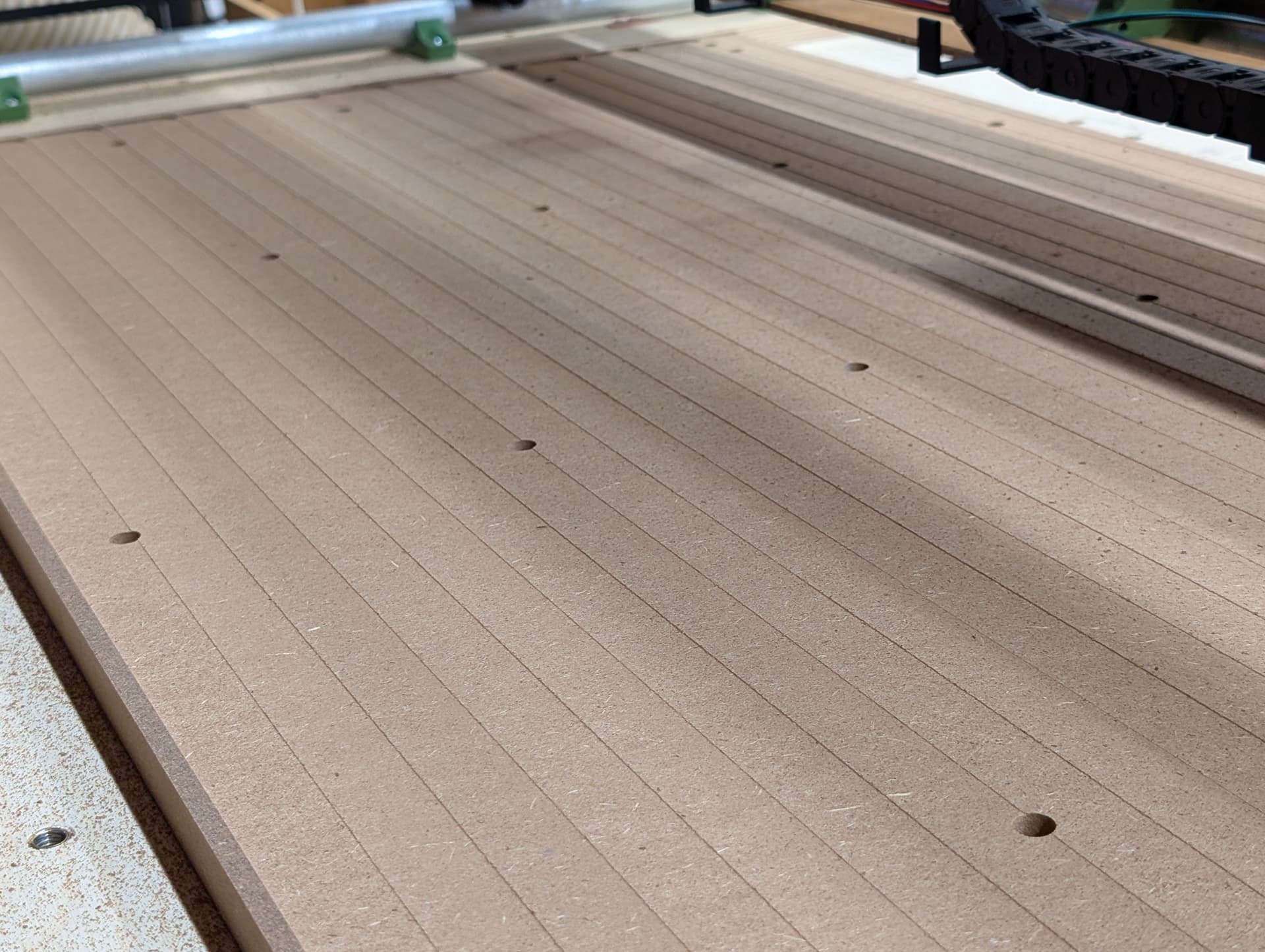
As the router goes from xmin to xmax, the sawtooth pattern becomes more pronounced, from barely visible at xmin to kinda crappy at xmax (it does cut deeper on xMax so perhaps that’s a factor too)
If you see more of an issue with 1 side vs the other, its because your gantry and bed are not level in relation to each other.
That deeper cut will take your minor tram issue and make it more apparent as it moves deeper.
Tramming issues with core tilt will give an actual saw tooth pattern, which shows you which way the tool is tilted.
Once you have your level set, you will sees a consistent tram issue, and if you fix tram first you see a consistent leveling issue. Both are fixed independent of the other and i dont think it’s important which one you fix first. But you want to correct both issues.
Okay I’ll run another pass with a different stepover and see where things stand, I do see minor tram issues in the Y direction, I was just puzzled by the increase over X, but yeah perhaps it was just depth of cut on that first run.
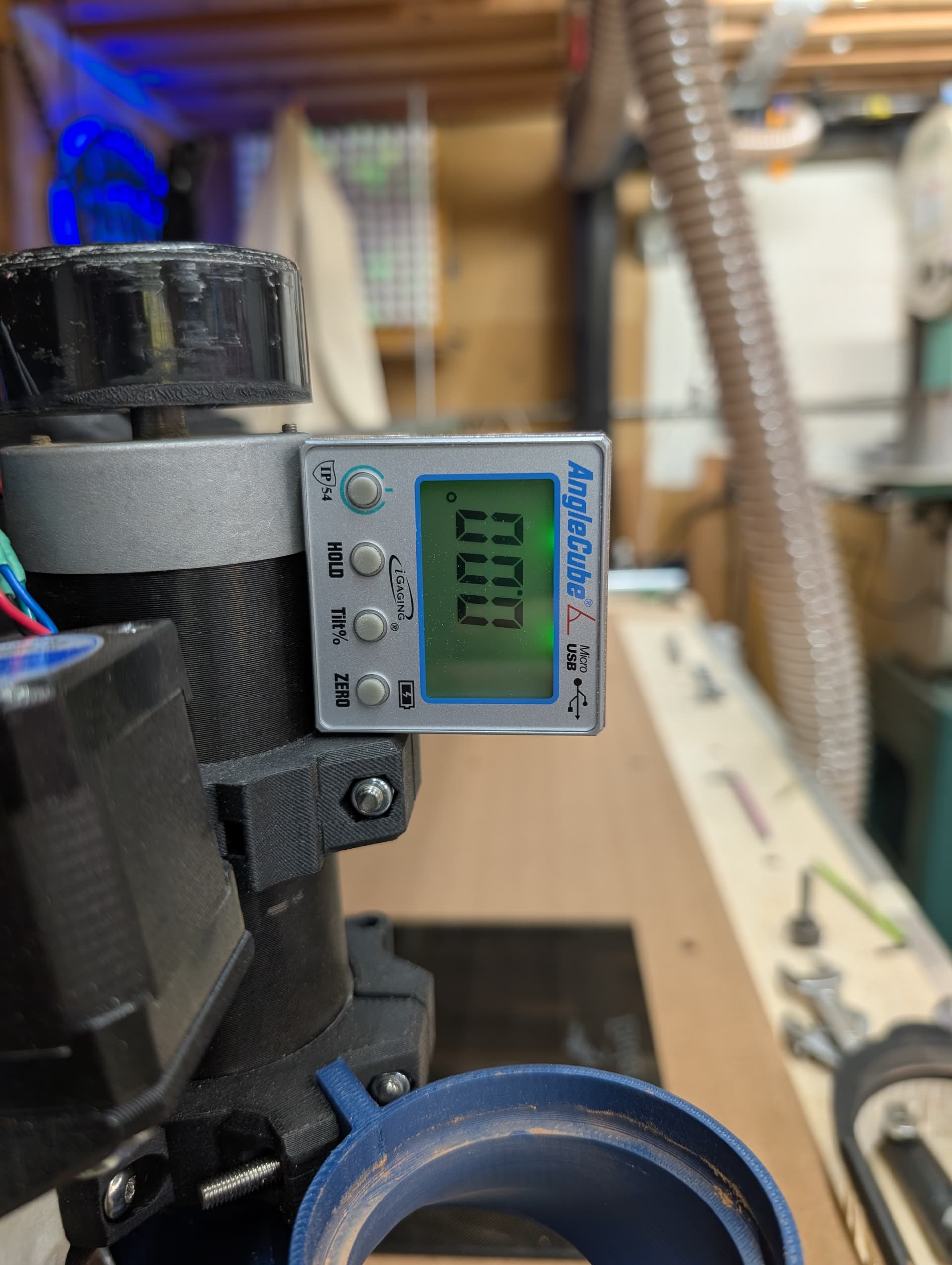
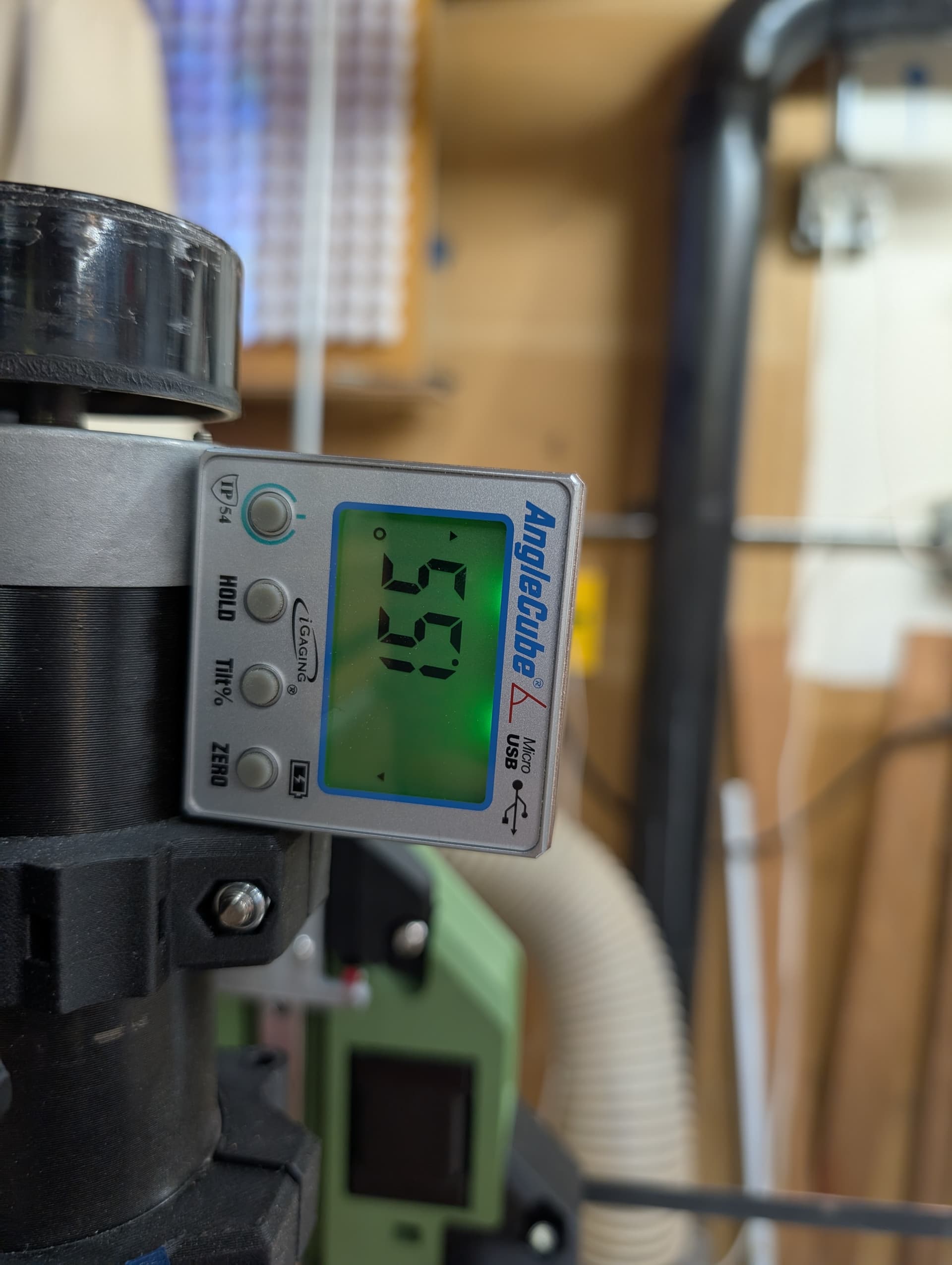
So at xMin the bit is perpendicular to the table, at xMax not so much. I was able to reduce the error to about .5 degrees by loosening the three screws and twisting but having a hard time completely zero-ing it out.
Is it worth disassembling such that I can potentially rotate the plate a bit after loosening the eight screws that attach the plates to the blocks? Any other spots I can tweak?
You don’t want to check if the bit is perpendicular to the table, you need to verify the router/bit is perpendicular to gantry/plane of motion.
Once that is fixed, surfacing will fix the table
There’s a long thread about this somewhere. Search “LR3 Traming” or something like that. It’s that thread, as well as the thread that caused that thread to start.
Fabian drew some diagrams to help explain, but having the bit perpendicular to the plane of motion is the most important thing.
Leveling the gantry with the table then makes it so surfacing removes the least amount of material to make it right.
Only other thing I can think of, would be to check and make sure the rails don’t extend outside of the braces near the XZ plates. Rails should have been cut with some room to spare and inset from the end by 1mm or 2.
We have seen that cause some funky behavior in the past.
There was another thread around here where someone else had a twist like this in their LR3… but I don’t remember what the solution was… I’ll search real quick and see if I can find it…
Your diagnosis is correct. You have a twist in your beam. (Side note, I’m going to start using that phrase in conversation )
Somewahere along the way between the early LR4 beta and now there has been discussion about stopping to check the beam isn’t twisted before continuing on. A 1.5 degree twist in the beam is way too much.
I’d start carefully examining the side that is 1.5 degrees out of whack, and if you do take it apart I’d start with that side.
Neat angle measure. Maybe find and compare various reference edges on XZ plates and YZ plate to figure out where offset is creeping into overall assembly.
Since 1.5 deg is on the Max side with rail/pipe, and we’re assuming Min XZ assembly and Router mount are good and both 0 deg (and not perversely offset but cancelling out to look like 0)…
Are ALL the Rail Rollers Bearings making contact with the Y pipe?
Asking because my Max side (rail side) rear bearings were floating even though front bearings were making contact.
Fix for me was to square up the belt holder blocks better (on Min and Max sides), set even belt tension on both sides, then square machine better.
I’ve tried a lot of these digital angle finders and this one is by far the best, highly recommended.
Think so but will double check.
I loosened and retightened the strut plate while twisting the beam back to zero which has helped a fair bit, down to 0.5 out but will dig deeper too see where things went awry.