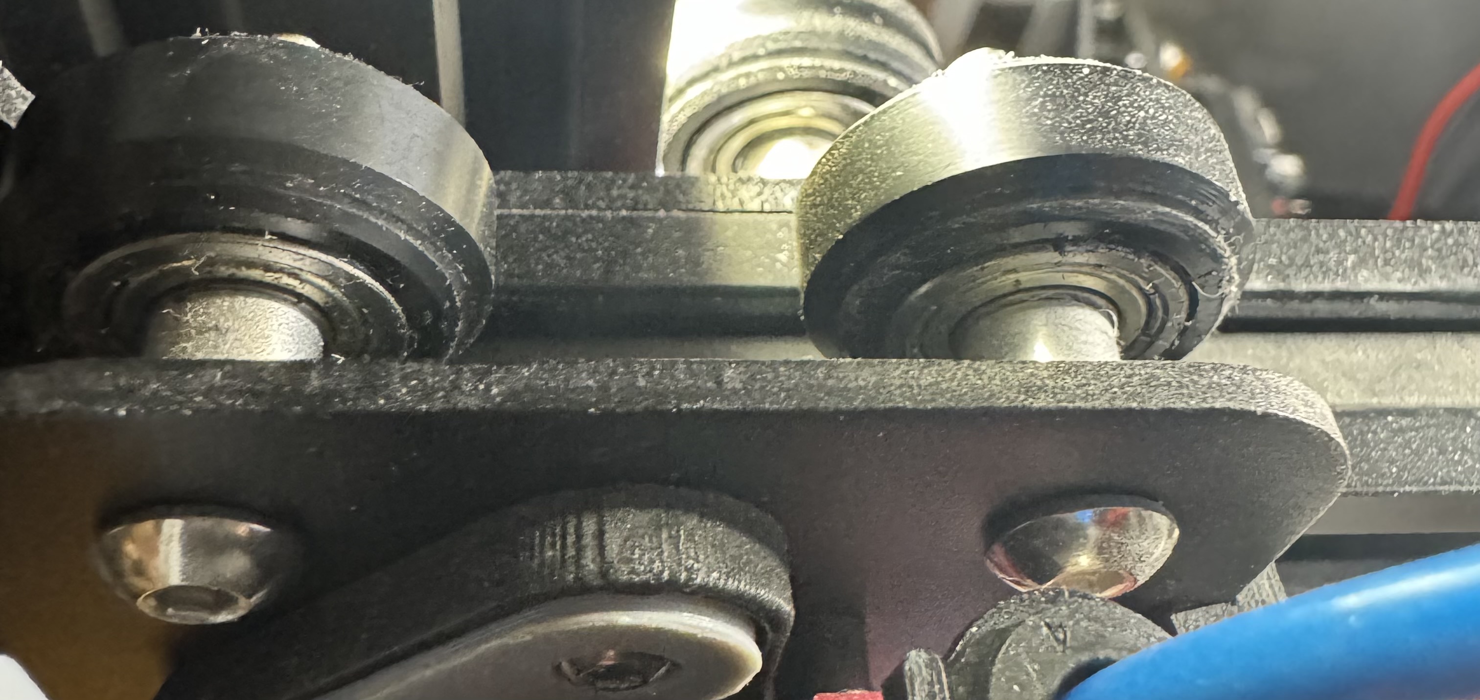
I have a DIY kit based pick-and-place machine that uses V wheels and it has been an abject nightmare with random binding in spots, the wheels picking up crud and running rough, all sorts of issues. I probably have less than 100 hours of work on it and the thought of it gives me mild PTSD…
Hopefully I’m the only person with this issue, but I doubt it
Adding a picture here would be rad so everyone knows what it would look like, pretty please.
Yes
yup
Not sure what that is, why do you think it is better?
I am purposely not being a cad monkey and CADing up every option. That is a waste of time. I really want to narrow this down. The CAD gets complicated quick if you have to go to far backwards it is usually easier to start over. My goal on the CAD part is not to make 6 printers.
I have never used them on anything but I trust that. The tolerances on two angled surfaces are crazy. That is why I do point load on a round rail for everything else.
Yeah, exactly. I’m sure they work decently in some circumstances but I think it becomes a case of how the pre-load against the wheels works out. In the machine I have it’s an eccentric shaft that’s used to set a very fixed position pre-load. As a result the pre-load goes from no force to bending parts levels of force with very little variation in size. That, combined with relatively lightweight steppers, made it a nightmare where it would just randomly skip steps if it tried to move over certain points slowly.
I have an O-drive board and a couple of hectic BLDC motors to mod into it at some point, but that’s one of those things that’s WAY down the list…
I get that completely! I have many of trashed CAD tries because of this lol. Honestly was surprised you were going there already. I figured for now you’ll just make pieces and not the whole deal. But you are the CAD master not me LOL
Linear rails are usually seen as an upgrade, and a lot of people do linear rail upgrades on these printers.
Unless there was a significant savings (including maintenance/replacements/etc. over printer life), I’d probably be inclined to go with linear rails over these.
better put 18 in the BOM so you always have a spare set on hand LOL. But then I would lose them and order a new set, then find them as soon as the new set arrived.
Yeah, they’re nicely made bits of gear. Pretty intimidating, though. I was having mine do step moves with enough acceleration that the entire 500g motor was leaping off the desk.
The lid’s extrusion doesn’t necessarily need to be on the bottom on the sides. They can be offset up from the vertical pieces on the front and back so that the bottom horizontal pieces can clear something moving on the top of the printer’s sides.
Right. The panels would sit on the outside of the extrusion.
The linear rails can sit on top of the extrusion.
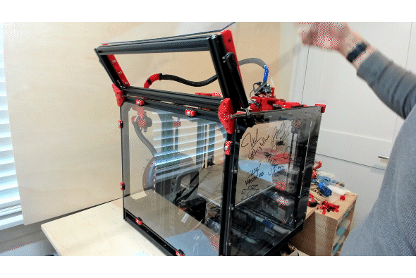
The lid’s horizontal extrusion can sit above the linear rail ‘stuff’ and only have the 4 vertical corner pieces go all the way down to the printer. I’m doing this on my printer. I’ll go take a picture.
Yes, exactly, we are talking about the same thing. Just trying to get the point that we can’t make a non extrusion box, and the panels can not be in the extrusion grooves (super clean but takes a bit of extra work).
If the rails are up top to save any room the steppers would need to be up top as well. Otherwise I think the belts and idlers take up about the same room as they are now. I have them as close as possible to the side (happens to be the thickness of the rail on its side (belt is just over the surface of the bearing).
So I think we are at rails sideways steppers internal (same as it is now), or rails on top steppers as well.
Some advantages to the rails being on top have been mentioned, but what is your opinion from an Engineers standpoint? I know you had Z height concerns with your print farm. Is there really a difference and if so is it enough to you being ok with it all being on top? And I’m sure there is a tradeoff in the enclosure department moving it all on top. Which it looks like David has already mentioned a good idea to overcome that.
If there is no advantage to moving the rails to the top then I don’t see an issue with them where they are now.
I am pretty sure I prefer them as they are now. I don’t see any huge downside to on top other than the top surface becoming a reference plane. As I design it is easier to keep track of three planes than 4. That could be better or worse, kinda hard to say. Having more surfaces to work with can be easier, though.
The plate sounds like a good idea, I looked at it last time, it just seems expensive.
The way it is now is a blessing and a curse. It takes adjustment to get it perfect, the blessing is you can easily adjust everything in an extrusion build. and the idea of making a wood or plastic box is appealing to me, but I have not done it in a couple years.
As it is now, seems more compact but in reality you have a reverse bowden sticking up so there is really no treason not to go up. We can route wires lower but we can not kink that bowden so that sets the height.
If we went under the extrusion, that is basically extending the sides up and going on top…if that makes sense. False wall.
Need a glaring reason to not go one way or the other, and its just not really there at this point. Really any of this sounds good to me. But I’m not the one who has to make it all play nice in Fusion LOL