I know its not the current topic but can we PLEASE put on the list when the time comes to talk about the use of heat set inserts instead of captive nuts??? PRETTY PLEASE!!! LOL
I want to look into this. I’ve never tried it, but I see people talking about it, and I saw it in the Voron docs.
Do you know of any videos out there that do a good job of showing the right way to do it? I saw some heat set sets with special tips on Amazon.
I just am not sure what is required, and previously when I’ve tried melting things into pla like nuts, etc., it seemed hard to get them to align just right, but maybe my soldering iron was too hot.
1 Like
I got a set of different tips off amazon cheap and they make it much much easier. As long as the hole is molded the correct size for the insert then its super simple and works great!!! I’ve used them in some things around here like my sensor boxes in the garage that I know I’m still messing with and will need to take the lid off several times. CNC kitchen has some good videos on them


He even sells his own and the tips for soldering irons…
1 Like
My concern is I’m pretty sure they are weaker. You’re relying on the bond between the teeth and the PLA. With a capture or through nut with the right orientation you get the full strength of the PLA.
On something like the bed bolt to the z motor bracket there is no tension at all. I know its not something we take apart often but it does sometimes need to happen and when it does its a REAL pain lol
1 Like
Well, they do make it for sure, it’s what I use for those.
The 6mm belts have a singular advantage in their use with the V slot extrusion.
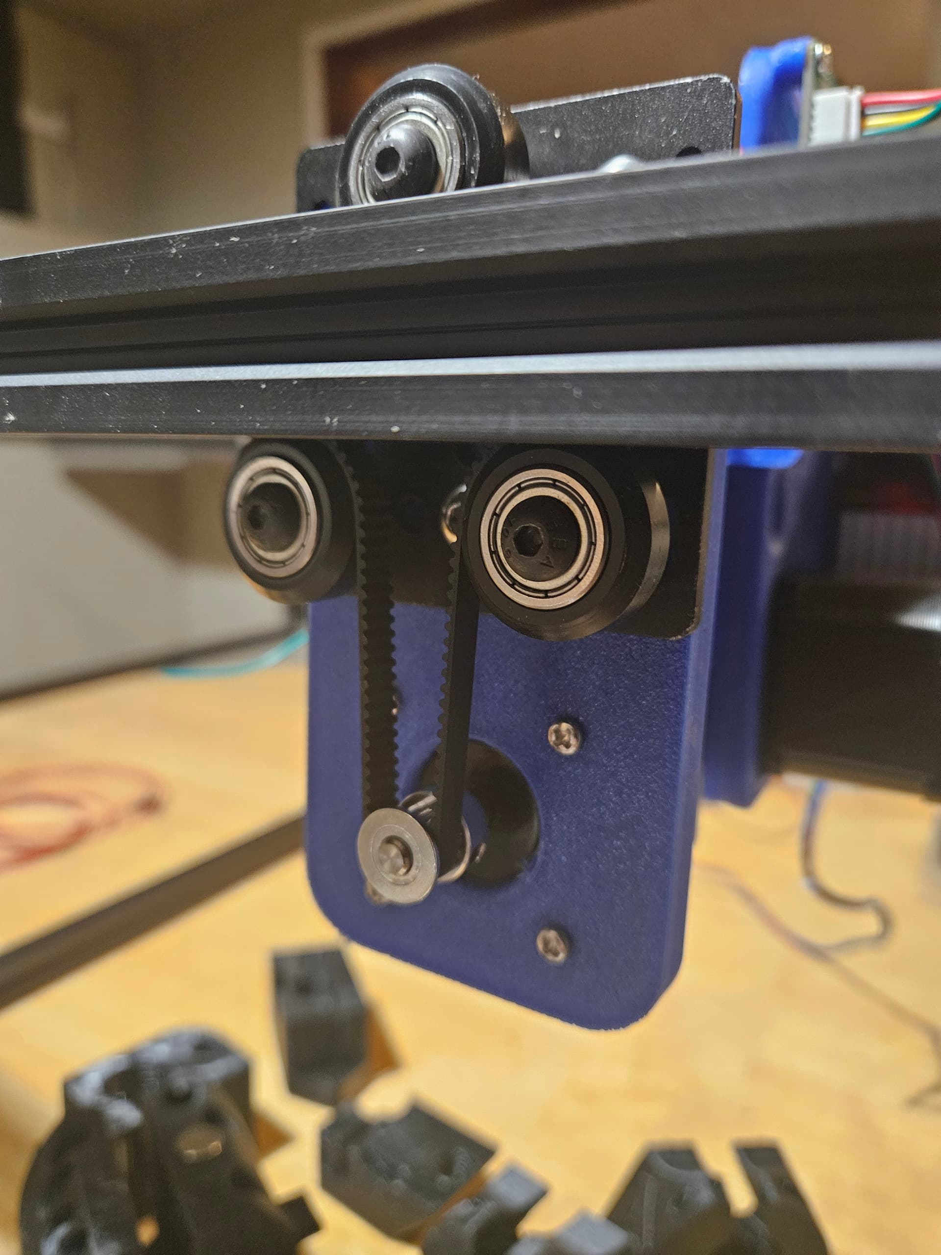
And there it is. No separate idler pulleys, reduces part count and complexity. I think 3 of these is plenty adequate for the Z axis at the very least, and then for the XY stage, using 6mm simplifies the BOM. Note that any gap between the gantry plate and motor is unnecessary. I have it for reasons which seemed like a good idea at the time, but I’d do differently if I started over. (This way is less critical of assembly order is all.)
I don’t think 6mm belts are too limiting for a 3D printer. Nothing a printer does should exceed the strength of a 6mm belt.
Would I use it? Maybe. Honestly I like the 10mm belt more, but as I said, I dont think that 6mm belt is a limitation. Some pretty fast printers use 6mm belt to great effect.
In your case though, it is a separate set of inventory. Motor pulleys, smooth and toothed idlers all need to be separate items, which is inconvenient, not to mention the belt itself. Its only real benefit is to remove 6 idler pulleys (plus associated M5 screws) from the mechanism? Thats a pretty poor cost/benefit ratio, and when you add in people’s bias towards overbuilding, it may make the printer less appealing
So while I think it’s possible without sacrificing the superior bearing parts, I likely would not make that design choice for a printer. (I did make that choice for my CoreXY to make the XY stage have a smaller height dimension, and for the new laser to rid the design of idler pulleys and hide the belts in the extrusion.)
This is cool. Glad I thought of it ![]()
Note that if you short both coils, it doesn’t (really) matter if it falls anyway, back EMF reaching the board will still be zero, because it’s been shorted out. With one coil shorted, what matters there is if it’s enough to slow down any drop to the point where the board can handle the back EMF.
2 Likes
Personally? I think v4 is already there, minus the belt attachment on the core ![]()
3 Likes
I agree and disagree. Its a great printer and it has taught me a TON!!! But I do think there are some refinements that can be made to make things better/easier as well.
2 Likes
I think you have done very well with that so far and it is cool to see the process unfold. I like the v4 I built. I would like some of the assembly aspects to be easier and the wire routing to be recommended, but it is functional.
So we have core xy, size, z bed motion / motor mounting / braking, xy stepper location, extrusion frame or panels, belt width, rails or carriages… Where are we?
I keep the first post updated.
1 Like
Just curious. Whats keeping you only slightly favoring the back position for the xy motors?
The consensus did not seem clear, and when we get there we will see if it costs space. I am going to start that way, though.
For bettor or worse those parts are going to be pretty large, I think I can contain them all in a 42mm width across the back.
1 Like
That was painful on my phone to scroll up that far… Kept initiating a reload and had to start over a few times. We are on gantry rails. Top vs plate vs side. The y rails are on the sides currently and the x is overhead. I would ask for a lower profile top end so whatever way that works is fine with me. I could envision the y rails below the top extrusion, but that makes enclosing more difficult. A side mounted x axis might be interesting, but not sure there is a compelling reason unless we could shave space.
1 Like
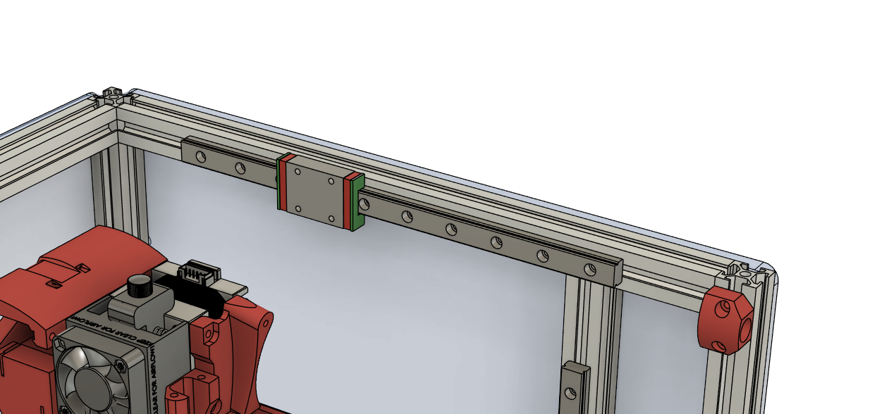
Side Mounted Rail, top mounted rail, or plate mounted rail (top or bottom).
Side
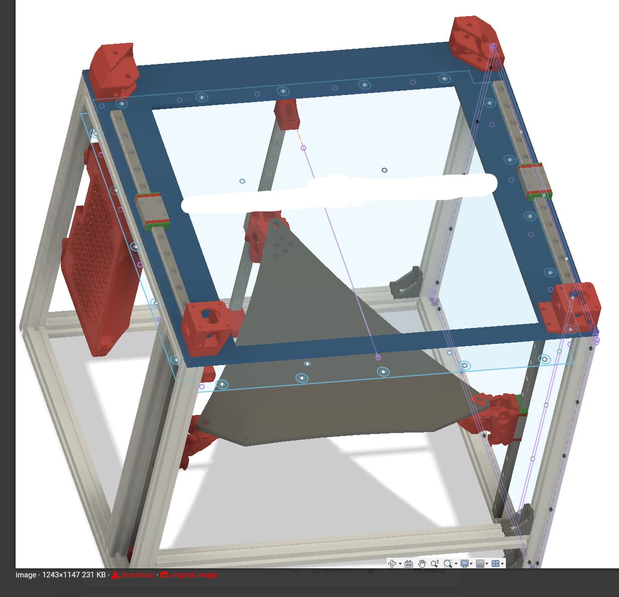
Plate top mounted.
The rest are variations.
Side mount, Pros - Slap it on an extrusion and go. Z skew is easily fine adjusted. Cons complicated connecting part and XY adjustment is frame based (trapezoid).
Top/bottom mount rail on extrusions - Similar to side mount, XY adjustment is easy, Z skew is frame based (one piece of extrusion for each rail).
Plate mount Top/bottom (optional front brace) - Pros can be easy to assemble XY squaring should be the easiest, this would sort of be drop an XY system on a frame. Cons - cost of a precision metal plate with tapped holes (or just m3 nuts). Z skew is dependent on the 4 corner posts (a super thick plate makes this better but the arms can still flex up and down. The other con is if you want an extrusion based lid this will cost space mounting the rails flat bringing them in 20mm on each side. The 4 corners would only be supported on one side not inline with the belt force so the piece would be larger to distribute the load.
1 Like
After this one we can take a break and I can start on some CAD for a bit. We will switch to minor CAD choices for a bit.
I did not ask about V wheels up here because I do not think they are well suited for this high abuse section. I assume we are all good with the longevity of linear rails in this situation. (Z is still open for discussion later).
I “think” I like the Bottom mount better.
This is more of an “I feel like” thing though, rather than substantiated in anything. Somewhat based on other printer designs I’ve looked at.
Does putting them top/bottom free up any space for motion of the toolhead?
Or what about torque on the rail block due to gantry weight? Is it better one way or the other? “Feels like” maybe worse on the bottom…
Side mounted: Seems that the majority of the load would be on the top of both the rail and the bearing truck. It does minimize leverage from the weight of the gantry though.
Top or bottom mounting: Evens out the load. I agree that the joiner is far easier to develop and probably print. Top mounting will cause issues with motor alignment as they MAY need to be moved up out of the box envelope to keep belt tensions under control.
Plate Mounting: Not a fan. Adds one more part that requires machining or very careful cutting. opens up issues for misalignment unless you have a precision cutting system (I know most of US do but what about the average builder)
1 Like
Not if you think in terms of adding an extrusion based lid, at that point it loses 30mm or so because you have to move them in to clear the frame. Make sense, if you have the rail on top the extrusion there is no room to stack an extrusion on top of it. It has to be a frame less bottom and at that point It would need to be an externally mounted panel.
With that said, using a top or bottom rail means An extrusion or plate is necessary. Currently, we use three planes, top or bottom requires a 4th plane. So we can currently still use a non extrusion box, this would mean extrusion or plate is needed.
Liking my lid with just extrusion at the rear.
Is this also a con for top mounting to extrusion? But with bottom mounting you at least have 4 Z extrusions or walls to fasten to?
Bottom mounting being mount linear rails to underside of upper Y extrusion?
What about mounting to angle extrusion?
1 Like
There you go with all the tradeoffs again. LOL. I get it I do.
I completely agree with you. I’m good with them for Z but not for XY.
oooooooo… Pretty Pictures!!! Seriously though sounds exciting. Always makes it easier to see it rather than just envision it lol
I’m not sure I’m following you here. Trying to picture what you mean by “plate mount”.
1 Like