I really like the look of this! Would be super simple to mount any combo unit to that front plate. Also would be super simple to extend that front plate out a little bit to mount an extruder on the top and hot end on the bottom as well! This seems to really give a ton of options with the bearing on top.
I guess this depends on if you have a door on the front of your machine or not. If you’re OK with the fan sticking out from the front of the machine, then you’re correct. Moving the fan to the back takes more space. But if you’re trying to keep things from leaving the front of the machine, then moving the fan to the back allows the extruder to travel further forward. You’re just shifting the build plate forward the amount of space the fan used to take up.
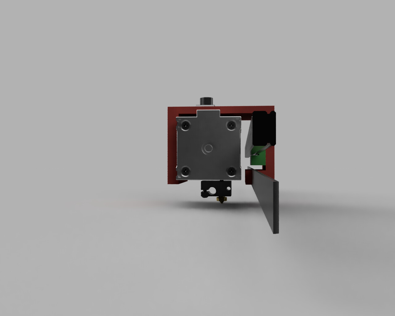
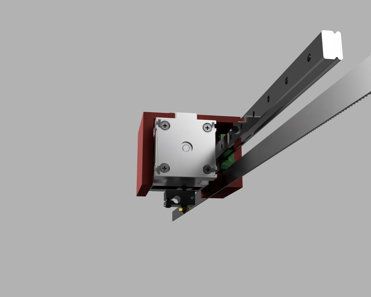
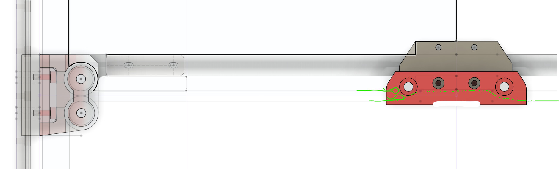
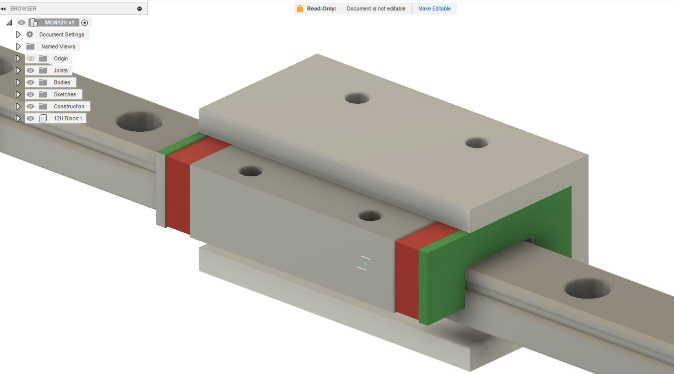
I tried to throw something together. What I’m trying to show is that if the extruder bolts from the front of the U, then that leaves that big opening where the extruder is to hook around the bearing block before screwing to the bearing. This leaves the area under the bearing block available for belts. The extruder could be brought closer to the back of the rail and clearance would have to be made for the stuff on the top of the extruder.
The red part in the picture is the ‘core’. You can see how it hooks under the bearing block for belt attachment (to be designed later).
Yes. Absolutely. Out of everything on the machine, this is worked on the most and needs the easiest access. If I can easily remove 4 bolts and undo a few wires and remove the entire thing for servicing, even better. For those of us with the means, it may even mean the ability to dedicate different extruders for different filaments. Want to print ASA at really high temp? Put in the ASA extruder. Want to print carbon fiber, toss in the one with the stainless nozzle. No more worrying about different plastics in the nozzle causing clogs or trying to fiddle with a wrench under the extruder swapping nozzles.
For those with machines in production, if an extruder fails, drop the whole thing, install a backup and keep printing while you work on the extruder on the bench.
1 Like
Thoughts on single extruder, but REVO nozzle per filament type if diff material types is causing clogs?
1 Like
That just means another parameter to enter into the CAD. It works either way. If it is on the back you need a stop so it does not hit the belts, if it is on the top or bottom no parameters, front and it exceeds the Hemera dims then yes another parameter but you do not have to adjust the back mount plates to add a stop to not hit eh belts.
Does that make sense?
Same if you add something to the side you would then need to move the endstop.
Not saying it is not an option, just that it seems harder to account for.
When we get further we will need to start adding parameters beyond bed size and Z travel.
And adding a stop so you can not drive into the belts.
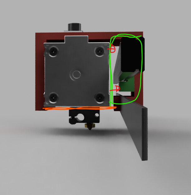
So if we made the green part, you are just trying to not have those red screws facing back?
If you want to have those screws in the front, it would really really need a orange brace.
I think in any orientation, that sort of Mount would work.
Do you have to get at your extruder Mount screws very often for it to be a big concern? On mine, I have to pop the heatsinks off every so often but never touch the actual mount. On the v4 you can get at all those screws from the back if you have to. But in doing this you are moving the bearing screws to the back, would they not be better up, or down so you are not getting to them from the back as well?
Man, if they priced those a little lower they would take over. They do seem to solve a ton of problems. Maybe they are more prevalent than I realize. I have ALMOST switched over sooooo many times.
Could take advantage of software limits to keep that from happening.
The other stuff is only cheaper if your time spent unclogging it all the time is not worth anything.
I’ve paid that price for too long, from now on anything I build will take this into consideration.
Only when playing with different filament types and monkey tightening things and breaking them.
So… Yeah. I’ve had to remove mine a few times since building it last summer.
Up would be most preferred. But not sure how well that would work with belts over the top too.
Oh. What about homing the machine to the back left instead of front left?
I have not had a single clog since I went to 0.5mm nozzles.
That means a parameter in CAD and in firmware, and the firmware one only works if you home first.
Has anyone else had this issue? I am not sure if I need to include this as standard or just account for it in in the design as an option? I know my experience with the farm is not the typical users. I use mine a lot more than most but I am not changing things all the time I just maintain and run. So on the farm I have not had an issue getting to the back or needing to remove and tighten.
The belts are currently in the front / side.
We can, then you could put your fan wherever and use an adjustable extra switch mount (or sensorless stop).
Is anyone else wanting the fan in the back?
I’ve had to remove mine a few times as well. But I always chocked that up to my numerous newbie build errors.
I might depending on how other things play out. Homing to max on X and Y wouldn’t hurt my feelings at all. In Klipper you have to home before you can do anything else so that’s easy as far as bumping into anything. Homing in the back makes it where at the end of the print its already back and out of the way if you rehome XY after a print
1 Like
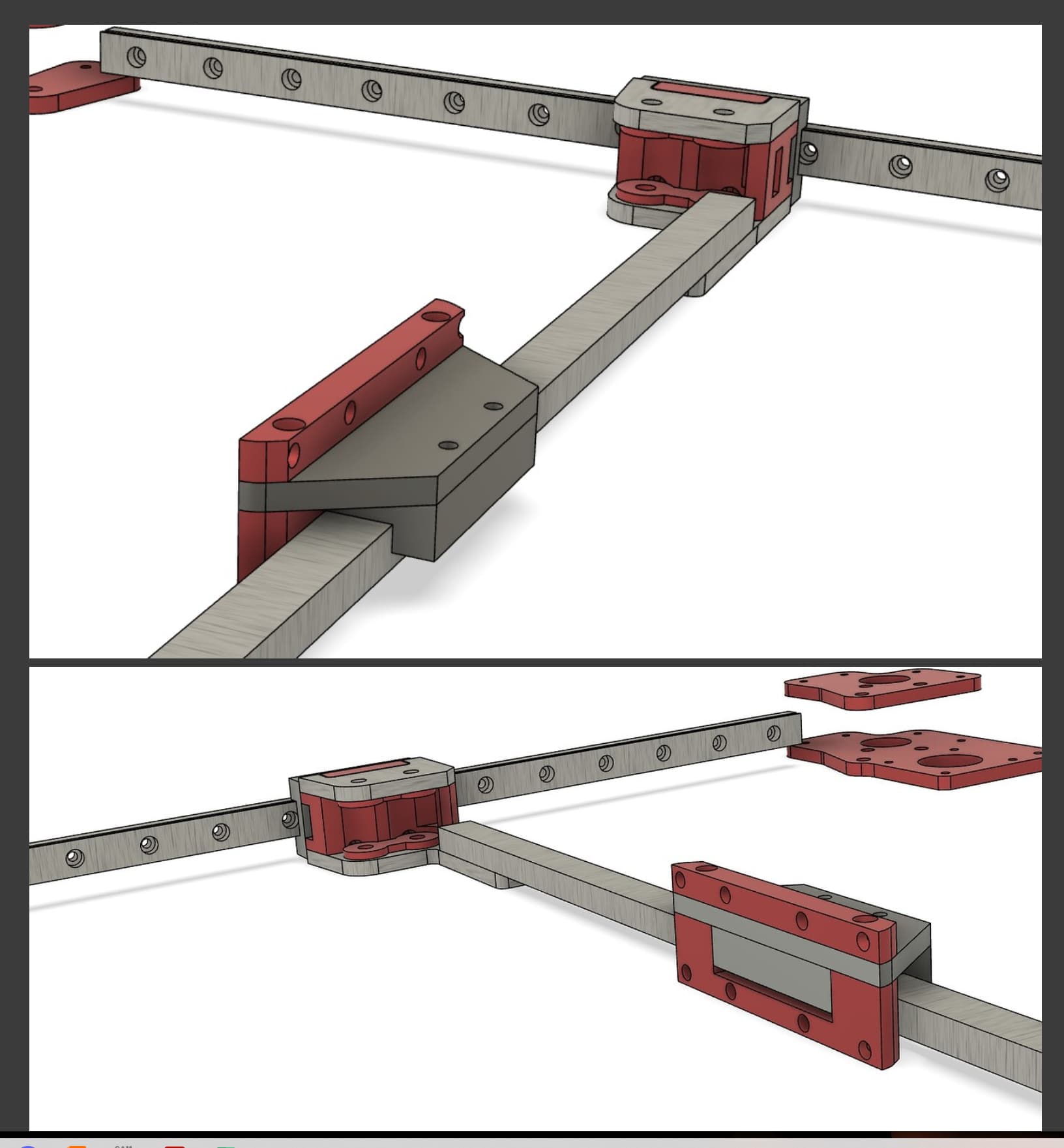
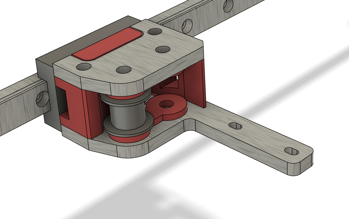
This is about as far as I want to take this until the X rail orientation is decided.
This is about where the belts fall The front is out a bit too far I just eyeballed it wrong.
The belts would get secured into the bottom piece and the top locks them in. This does mean the extruder would have to come off to get to the belts. Although they are far easier than V4 and do not get pulled into place so I suspect most will get them right first try. And I will know to leave more than 10mm per side adjustment.
The inside belt needs to get terminated, the outside one does not have to, not seeing a huge advantage to leaving it other than I think it is a bit easier, terminating would be a tight fit but probably a stronger option., I think I can leave room for both. This would be pretty similar to a vertical plate. Unless we get the rail above or below the belt line.
After looking at this, what I am seeing is bearing screws at the top, printed mounting plate in the front. and the lower truck plate holding the beam and idlers. If we go vertical, the bearing screws will be behind the extruder and on the trucks either the idlers get the plates, or the beam get the plates, both probably will not fit.
If we go vertical plate with the bearing screws facing the back we have a “C” channel printed part the extruder and things mount onto.
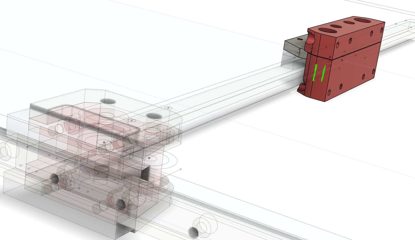
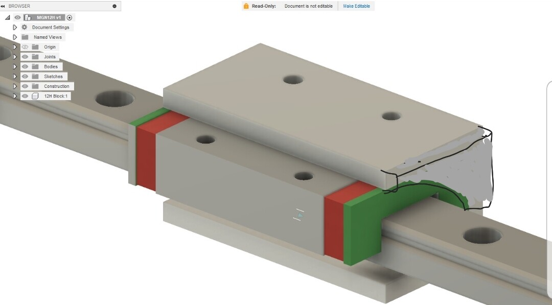
Like this, or the green way,
So my vote is either the way I am showing in the first picture in this post, or bearing screws facing the back (green way). Either will be fun, I kinda like the idler and rail sharing the plate better.
If I am following you correctly, with the bearing block on top we get the idlers and the rail secured to a plate at the Y trucks correct? If so that sounds like the strongest option to me and gets my vote
That doesn’t bother me at all. I Like it!!!
I was thinking up ideas, and the one I like was for vertical orientation.
C channel. Bolt the C channel to the rail car from the back. Easy screw access, and mojnt points for belt.
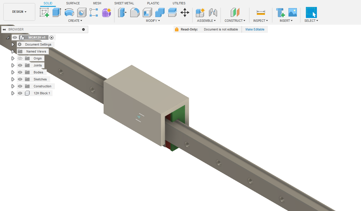
Bolt the extruder to the C channel on the front. Use 5/8" ID (7/8") × 1/8" thickness. The MGN12 rail is 13mm “thick” on edge, and you get about 3mm clearance to the back of the rail. This makes your bolt surface about 6.2mm from the back surface of the rail. You do only get 2 screws to attach to the car as a downside, I guess, and just the 23mm or so width on the front in aluminum, but the extruder will be closer to the center of the rail than any other orientation I could think of, with minimum compromise of space in Y or Z.
It would probably have to be a printed C channel That is a lot of holes to get just right to Mount to a back plate, get the belts in, and mount an extruder. I am seeing this as a metal backplate on the bearing and a printer part screwed to it. otherwise, a lot of things will need to get drilled into a C on multiple faces. Thai is asking a lot when a printed part does it easier. Thank about multiple fans and can bus cards.
Unless I am not reading /visualizing that, right?
I will check back in the morning.
1 Like
Yeah, it is a lot to get right, but I was actually thinking 4 holes. 2x 3mm on the car face
The back surface still gets 2 screws into the car for a printed part to hold the belts. It should be enough.
But … yeah. To get the holes in the right place for the M3 screws pretty much requires a drill press. (Which, of course I have.) Maybe a printed guide block could manage with a hand drill, or of course the possibility to CNC machine the 2 faces isn’t impossible.
The alternative for a printed part would probably be a tube that you have to fit the rail through before bolting it to the Y axis. This would allow it to have the strength to tolerate the belt pulling for high acceleration in the X axis. This part would then also include the add-on parts that would hold the belt, and could use all 4 screws on the bearing block.
I was thinking of the C channel as a “skeleton” of sorts. A rigid mount for the extruder to the bearing block, and then printed parts to hold belts, fans, daughter boards, etc.
I like the balance of having the extruder as close as possible to the center line of the load bearing blocks in the Y axis. It feels like that would result in less wear and tear on the bearing block.
1 Like
If printed, are you guys thinking sidewall reinforced C channel?
Guessing overall printable area is being kept in mind. So many variables and tradeoffs ![]()
Sorry. I meant to say cables.
Does anyone ‘not’ home before printing? I thought that was the norm on 3d printers.
Again, my only real argument for the fan on the back is to counterweight the extruder on the front.