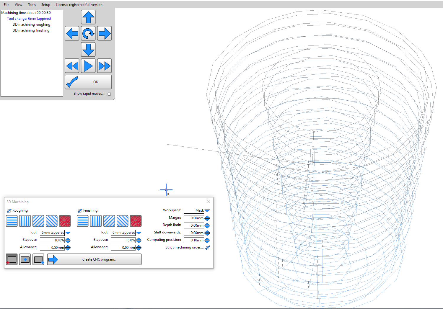
Does anyone have suggestions for generating circular gcode for each layer. It is a truncated cone, but the generated code consists of short straight lines.
My machine “understand” G02 and G03. I use GRBL settings because my machine is not in the list.
This is just a guess but have you tried changing the computing precision to a smaller value?
1 Like
And have you tried it with 11? V12 is still alpha. ![]()
you are right, did not try it in 11.
Update:
In 11 the same, and with the suggestion of Dreyfus, the lines are shorter but still straight.
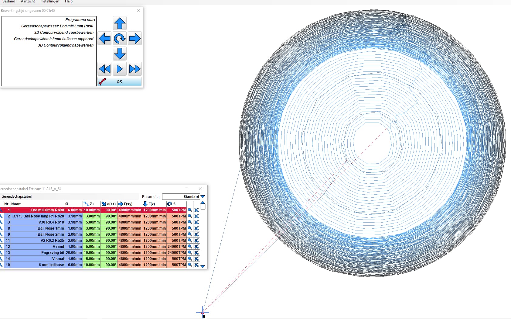
This is kind of weird, have never seen this so far. ![]()
The most optimal gcode would be a helix. I can generate the helix in my cad program, but how do I get Estlcam to generate the gcode of this line…
The second option is to draw every milimeter a circle but then again; how to get Estlcam to generate the gcode automaticly
I would check to make sure that the .DXF is actually a circle. This can be a bit tricky, but if you open the .DXF file in a text editor, you should be able to see if it’s a single circle or arc object, or a ton of small lines.
I know that some programs will see a bunch of small lines approximating an arc and try to automatically replace them with an arc, but I don’t know if ESTLCam does that.
Jono, Tnx for your input. I am very sure the dxf is a circle because it is not a drawn line but made with a formule in a professional cad program
For sure, but having worked with ‘professional’ CAD programs a lot (Solidworks, Creo, Altium Designer, Mentor Graphics), it’s still worth verifying the underlying fundamentals.
My approach is usually that if there’s a problem, double check all the assumptions about what is causing the problem. It’s very easy to spend a week searching high and low for a problem that doesn’t exist because it’s somewhere upstream. Spending 10 minutes checking to make sure this isn’t the case sometimes pays dividends ![]()
What’s the diameter of the outer circle roughly? Wondering if the straight line approximation is reasonable if this is a small cone.
top diameter 18.960mm
bottom diameter 13.338mm
top to bottom height 20.0mm
it is a truncated cone
Guessing actual cut will look pretty smooth if hole is just ~19mm wide and compute resolution was already tweaked.
How do things look on the screen if you zoom out to actual scale? acceptably smooth?
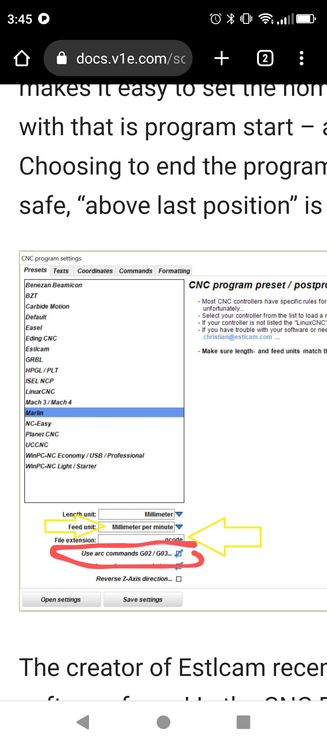
Able to ‘Use Arc Commands’ setting in EstlCam? Looks like that setting’s available for Marlin and GRBL in “Setup Menu > CNC Programs menu item > Presets tab”
For the naked eye it is smooth but I was wondering why a perfect circle was represented in short straigth line instead of G02 or G03 code with a center, radius, start and endpoint.
update: sure G02 and G03 are enabled
Useful info, at this point I’d double check the .dxf like @jono035 suggested to see if the CAD program exported a true circle entity, and not an approximation (represented by short lines)? Assuming EstlCam is parsing Circles/Arcs within the DXF, then… Am curious whether maybe EstlCam was coded to generate short straight line segments because that approximation is easier to code than doing the math for a 3d spiral (not circle arc, but a spiral with an ever reducing radius) using G02/G03. At this scale maybe Dev thought this was good enough? Maybe same strategy is applied to large tapered cuts too.
1 Like
Thinking about it, I wonder if it is because it’s tapered. If it were a continuous cut then you couldn’t do it with a single arc because the radius would be constantly changing, so it would need lots of shorter arcs, at which point maybe it’s better to not saturate the controller and do short lines?
If it were approximating the taper by cutting circles at each height then I could see that being a single arc command, move and height change for each height.
Edit: Regardless, I’d still want to check the underlying file.
Is it something you can post so we can take a look at it?
1 Like
Betting @christian-knuell knows whether, and why, straight lines instead of arc commands are intended to be generated for tapered holes? ![]()
1 Like
Try with another Gcode viewer as well. It might just be a visualization thing.
2 Likes
I agree with this. It looks very much like an export setting from your CAD software, I don’t think it’s the fault of the g-code. My son-in-law was experiencing exactly the same thing with F360 - it renders as a complete circle in the CAD package but exports at a lower resolution.
What CAD are you using? -
1 Like
And sometimes Solidworks does the opposite. Renders faceted holes but exports .step files with actual cylindrical features.
1 Like
Rhinoceros 3D, generate nurbs curves.