“Lines, arcs and circles in Rhino are good to go.
Twisty Rhino NURBS curves need to be converted to arc chains. If you don’t convert them, they will be approximated by hundreds of short straight lines.”
Not necessarily. Some tools, as I think I mentioned above, will attempt to detect things in import files that it thinks are curves.
In this case, there are clearly 2x Circle fields and a Polyline which will be the square around the edge so it’s definitely exporting ok.
So the next thing I would try is to have ESTLCAM pocket the circle and see if it does that with an arc command, then perhaps change the scale and see if it still does it?
I wouldn’t be so confident about what is going on based on what is shown on the screen vs what is real. As I said above, Solidworks will render cylindrical features as faceted in some circumstances. Just because it looks one way in the tool doesn’t mean that it is. This is why there was the suggestion to find a different visualisation software to see if that was still the case. I think it would be obvious by the number of lines in the gcode, though.
Actually, what are you importing into ESTLCAM? That DXF or the step file? If it’s the step file then I’ve never worked with solid models within ESTLCAM. Perhaps try import the DXF and see if it works as a pocketed feature?
Just as an ‘out of interest’ example, that’s what an extruded cut looks like in Solidworks formed from a 6mm diameter circle. As you can see, it’s clearly being rendered as faceted. If I export that face as a .dxf then it has a circle field defining the position of the circle and if I export it as a .step file, there are circle entries that look like they’re being used to define the hole in the middle, so it’s clearly just rendering the part as faceted, not actually working with it as facets.
Very interesting. Definitely seems like it’s the case. It’s slightly unexpected because it looks like it’s choosing to cut circles and then do a height change, rather than anything slightly more crazy like trying to cut a descending helix with a decreasing radius.
Perhaps the path handling for 3D objects isn’t quite as polished as it is for 2.5D. I expect it’s a lot easier to look at a circle in a .dxf and go ‘that should be cut with G02’.
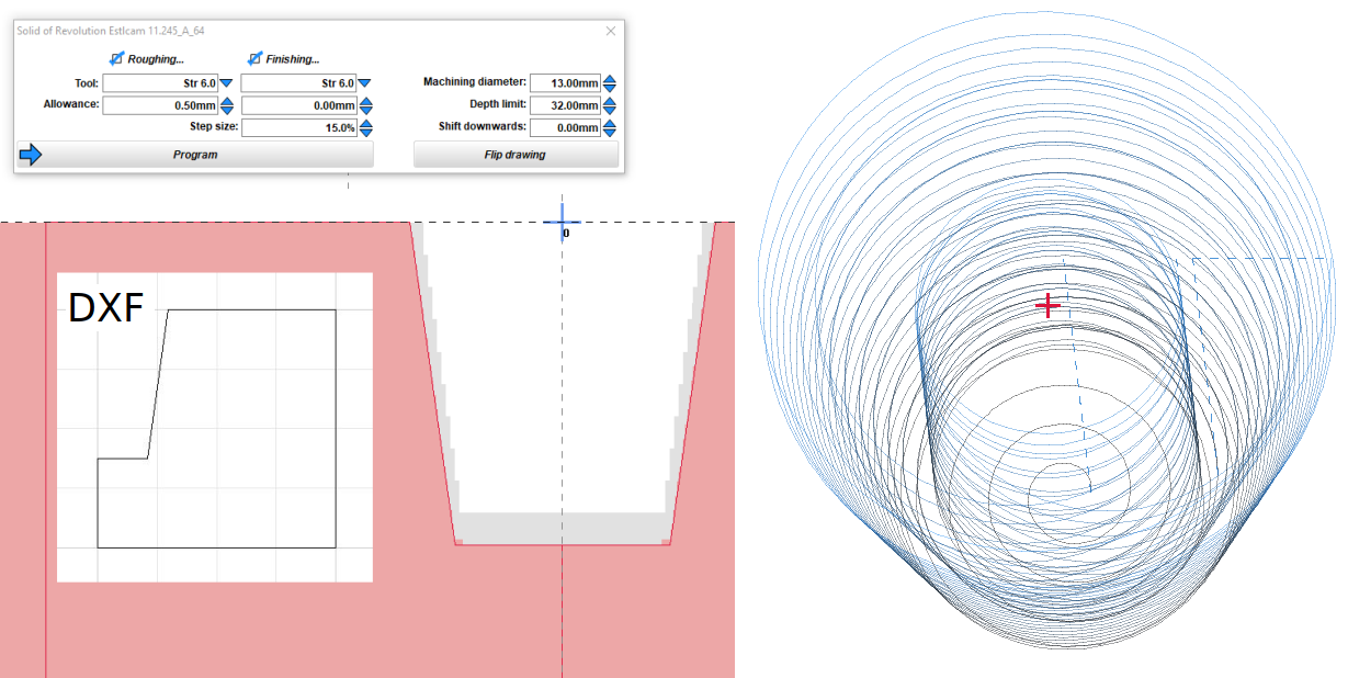
Solid of Revolution (v11) generates helical paths from half a 2D cross section, e.g. your truncated cone. Getting it to machine just a pocket (or hole) requires reducing Machining diameter (I also edit the g-code to remove everything from the 2nd to last clearance plane move).
the solution with solids of revolution was already mentioned, but a bit of background on the issue:
STL Files consist of triangles only - they can only approximate circles no matter if the design file format used real circles or not.
Some programs allow to adjust the conversion precision for STL export - and Estlcams 3D machining also has a precision setting - but for 3D in Estlcam the result will always be lines.
The 2D part of Estlcam uses real arcs and circles.