They must have gone to my junk mail! ![]()
Oh you gotta find them! Let me know if you cant
1 Like
Also, I think the z axis housing will work perfect for those who use the Y max homing and also for the core
1 Like
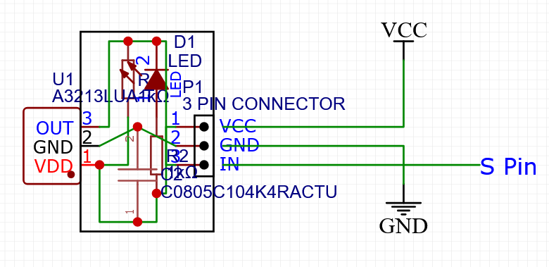
Definitely want a current-limiting resistor on the LED. You can set its brightness with that. With no reststor, it will flash brightly for an instant and burn out.
1 Like
Is that what these are in @which_carpenter post?
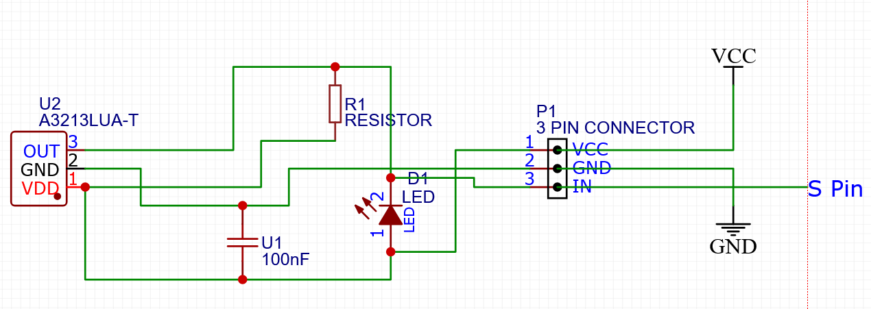
I’m very much a noob with circuits sorry. Where would I put the resistor and would the ohm’s be determined by the LED chosen?
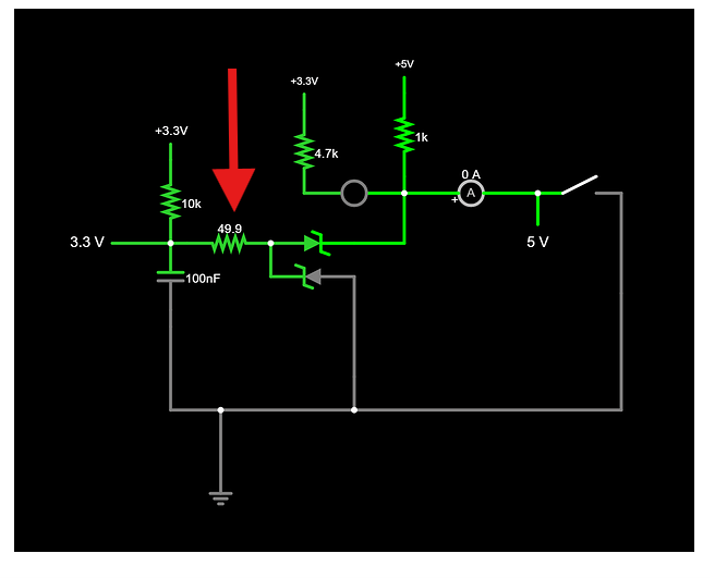
That green and black circuit makes no sense.
On your diagram (white background), put the resistor in series with the led on either side of it, before you get to the red dot. 100 ohms, very bright, 2k maybe too dim. It really depends on the LED, so play around with some with the lighting you will be using in your workshop, to see how bright it needs to be.
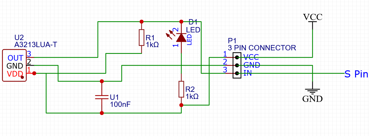
Yes, perfect, except try a few values of the resistor. If you have a 5k or 10k potentiometer lying around, you could use that to decide which fixed value to use. Just put a 100 ohm safety reststor in series with it while experimenting, or else the led will blow at the 0 ohms end of the dial.
2 Likes
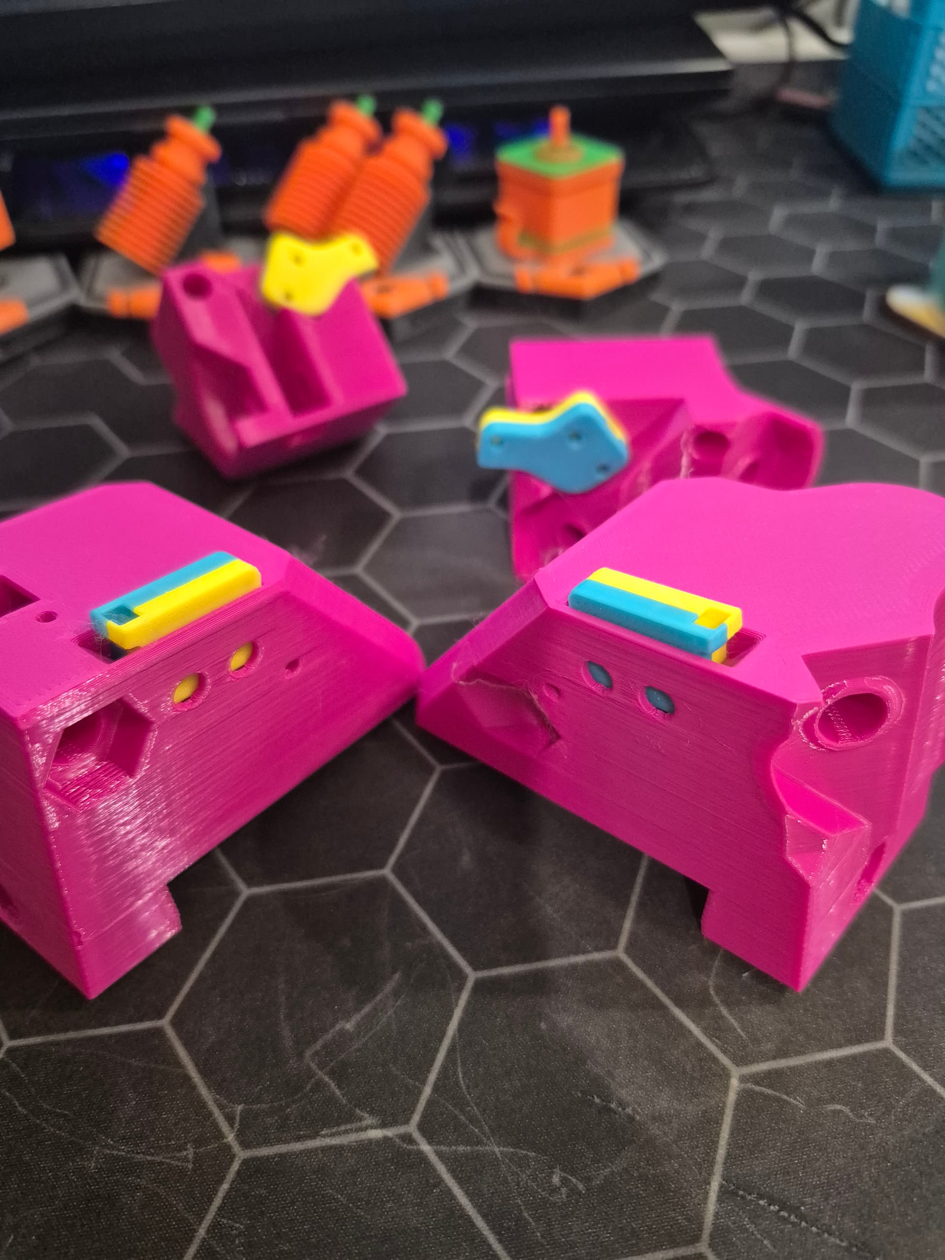
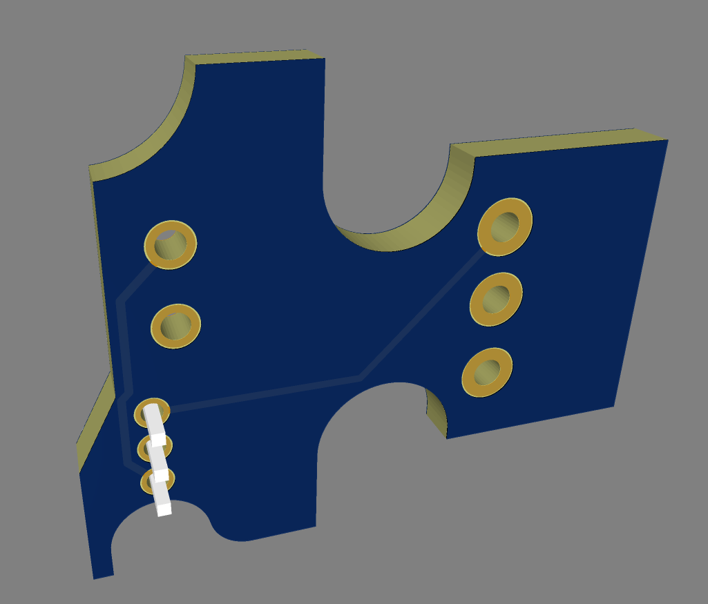
Thanks Steve! I will have a go at making the circuits as soon as all the stuff arrives. I might have jumped the gun a bit today with this project. I have been looking at the space available in the current housings. I have added a bit of extra mass to @which_carpenter Z Axis design (As I will most likely be using Max Y for homing so those will be the same for all my endstops) so that it will take a 3 pin JST 2.54mm Pin Male Plug with the pins turned down 90°.
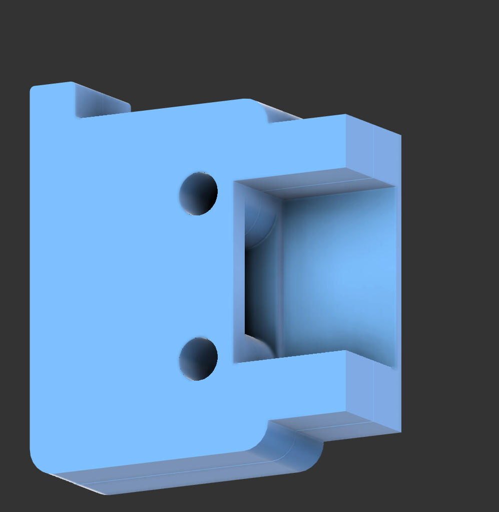
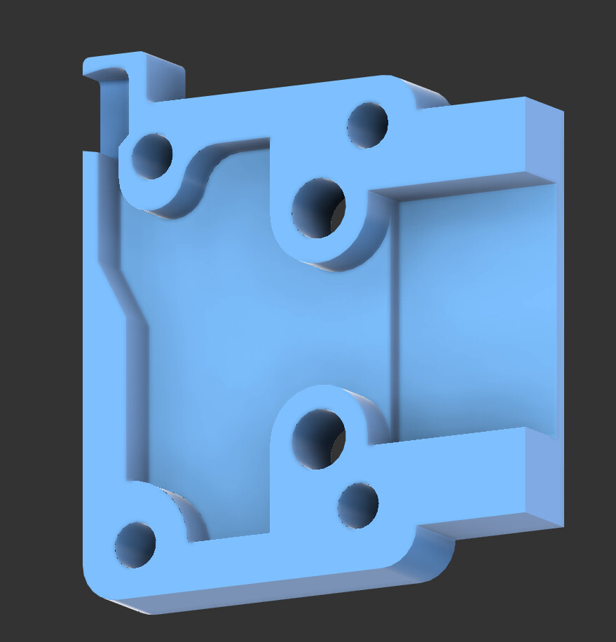
I wanted a LED status light to show when it has reached the limit. Will modify the housing to allow the light to shine though or have the LED bent to sit just proud of the housing. The other Idea was to have a SMD LED and have a 90° defuser to shine thought an opening in the housing.
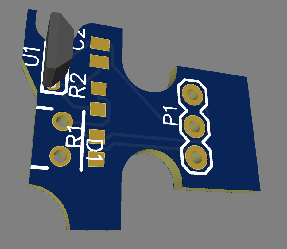
The HALL effect will most like be installed with the legs asa shown but will be bent up and away to the opening that is in the housing design.
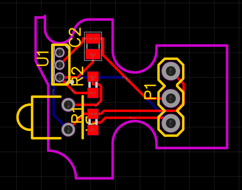
This idea might have gotten away from me a little. Not sure if this is classed as over engineering. But its my first attempt at circuits/PCB design. Thoughts?
7 Likes
Looks cool! I would see if it costs any extra to put a couple in a row with snap off pcb edges. It may be the same cost to make 5x instead of one.
4 Likes
Did a quick breadboard test today. Really impressed - the magnet could be up almost 10mm away and still trigger I defiantly prefer the idea of a ‘passing by’ arrangement.
1 Like
That’s the best kind of engineering.
2 Likes
This section of the circuit is from the jackpot 1 schematic. It’s where the end stops connect. The left 3.3v is a measurement not a source.
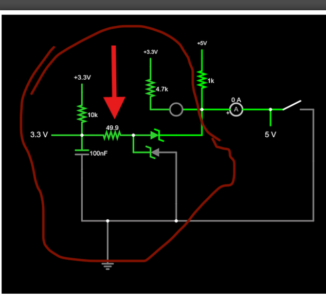
1 Like
I think the passing by arrangement would definitely be better for the z axis where crashing is more prone to move things around. I like the adjustment of magnet position for the y axis and I think it would get complicated to rig up a similar adjustment for a pass by but I’m sure it could be done. Another solution might be to just set up some sort of hard stop that before it hits the sensor which is what I plan on doing.
1 Like
Thanks for clearing that up @which_carpenter
Yeah it’s definitely more reworking of the belt tensioner block to make an adjustable pass by magnet block that way.
That said nothing says they have to be one piece I suppose.
I can’t do any more till my Amazon tray of ceramic caps arrives.
1 Like
I wince when I hear that. No offence intended to anyone but it’s not engineering at all, it’s just a way of saying “I guessed”! ![]() (and to be clear, there’s nothing wrong with that - we have to start developing the design somewhere).
(and to be clear, there’s nothing wrong with that - we have to start developing the design somewhere).
During my time racing and developing sailing boats we had a mantra - “If it didn’t break, it’s too heavy, if it did, it wasn’t strong enough” getting those things exactly balanced and calculating a safety margin is engineering, anything less should not be besmirched by the term! ![]()
2 Likes
Ignoring what I’ve said in the above reply - I’ve been half-following the above, and wonder if there’s a reason for having the electronics so close to the sensor. It seems to me that they could be located anywhere between the control board and the sensor, which may enable a much smaller package?
I wondered about a “hat” that fit over the endstop headers (with the 5V soldered in) and had the electronic elements on it with connectors. Similar to how the daughter boards work for the spindles and whatnot. Might make them “all or nothing” though. (All axes would have to be Hall switches.)
1 Like