Any help here @johnboiles ? I’m certainly not qualified to modify code for digipots seeing as how I just had to google what a digipot is.
I’ll be switching back to Marlin soon. Gotta get my machine back up and running after having high hopes for using GRBL again like I had on my little 3018.
You don’t have to code anything. I imagine it is in the config.h file and marked pretty clearly. It is already setting the digipots, you just need to change what value it sets them to.
Instructions: Paste the cpu_map and default setting definitions below without an enclosing #ifdef. Comment out the CPU_MAP_xxx and DEFAULT_xxx defines at the top of this file, and
the compiler will ignore the contents of defaults.h and cpu_map.h and use the definitions
below.
config.h
line number 690
*/
I was able to track that down in the config.h file. Mine looks identical. Is 135 the appropriate current value? I purchased my steppers from Ryan.
I may try reflashing again tonight and see what happens. Maybe something just got corrupted upon transfer?
EDIT – I refreshed and it’s alive! Not sure if it was something in the initial transfer, or if I may have had a very very low federate set up in UGS (10 was the default). That actually could explain the sound of steppers trying to move but not moving (enough to be perceptible). I’ll play around some more and send some GRBL gcode from something like Carbide Create and report back. Steppers are definitely still warm.
Tim – thanks for all the assistance in troubleshooting. I never really got a stable connection, and never got UGS to reliably send code without chasing error messages. I never even got around to trying to drop the current on the steppers. Waived the white flag and just reflashed Marlin. Already up and running and ready to make some chips again.
negative machine coordinates throws me off, work coords ok
no lcd, miss the dial for feed speed
no control when paused (“feedhold”?)
no way I know of to turn on/off “fan” terminals in g-code (I have relays tied to this controlling power to router and solenoid for air blaster)
Without the last one I cannot use this firmware. Anyone help with that one? I also noticed the speeds were a lot faster. I know I can turn down, just noticed.
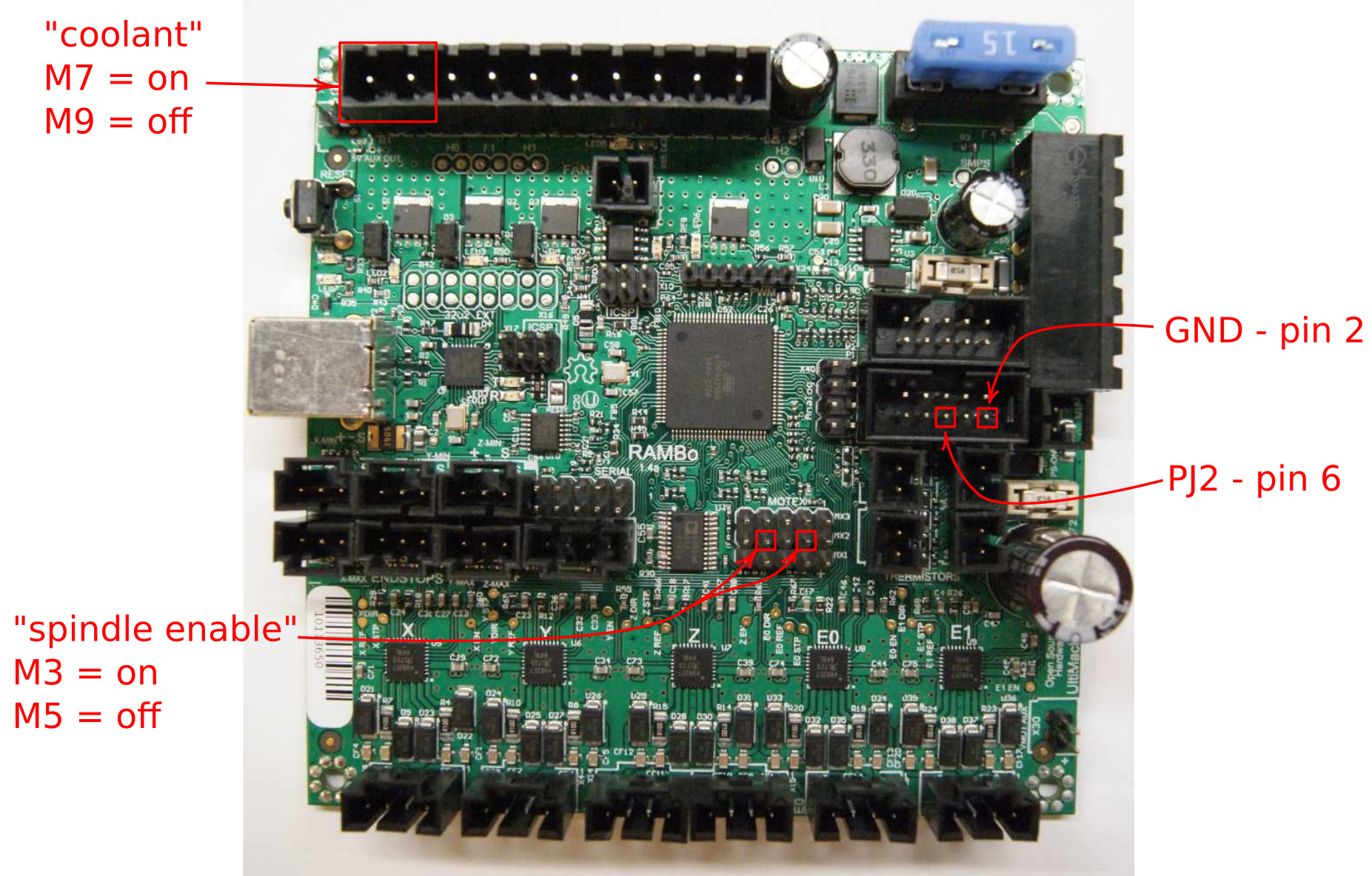
The “fans” in cnc.js are coolant indicators.
M7 turns on flood coolant.
M8 turns on mist coolant.
M9 turns off both coolants.
I’m planning to use relays on these for vacuum hold down and air “assist” to blow chips from the bit as I’ve got centralized dust collection in the shop already. I don’t forsee any issues with one command turning both off.
When I say “fans”, I’m referring to the terminals on the rambo board. I tried those commands. Did not seem to do anything. You have had luck with this on a rambo board using grbl?! If so, I could use assistance in learning it.
Sorry, I don’t have a rambo board. I misinterpreted “fans” in your post for the icons in CNC.js. I’m using a CNC shield/arduino uno stack running grbl. Because I’m using an older shield and trying to get spindle variable speed working my pin mappings are a little convoluted. I did need to enable the extra coolant pin option in firmware to get both coolant “channels”.
If you know what pins the fans are on you could probably remap the firmware to call them coolant flood and mist. Or, find the pins that are already mapped that way (a4 and a5, I think on mine) and hook you relays to them. The fans are probably pwm, and you only need digital on/off to drive the relays.
@dhuvelle did you ever get grbl running on the lowrider with endstops (2 on Y, 2 on Z) for auto squaring? I understand we need to reassign the MPCNC axis 1-5 from X,Y,Z,X,Y to X,Y,Z,Y,Z in config.h similar to the marlin edits from MPCNC to lowrider. Was there any changes to reassign endstops for the lowrider config? I was wondering if you ran into any other issues or necessary edits… I plan to flash my Rambo board and start troubleshooting, and your experience will likely save a lot of time! Thanks!
Okay, I think I have something going here. Fumbling through the dark with this stuff, I have my Spindle and Coolant both working within cnc.js, rambo 1.4, and grbl using John’s great work. In case anyone else looking for this, this is where you tie in your relays or what might have you. This is not changing any cpu pin mapping. I understand that most may already know this. This should also answer @victord question from awhile back.
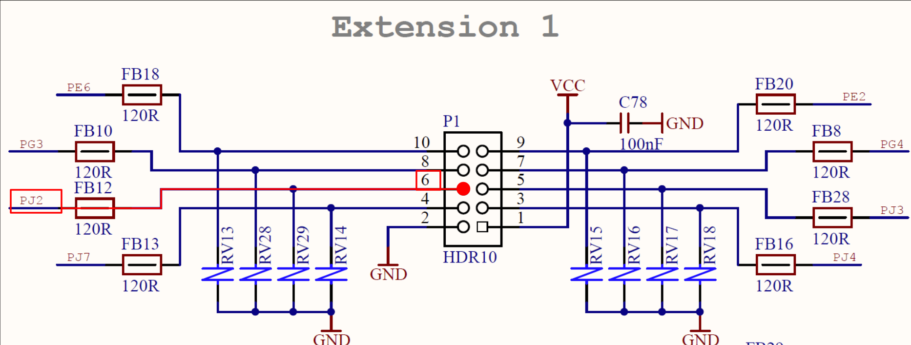
Now, I have also tried to wire a physical button input for Feed Hold (pause) to the LCD connections, “Extension 1”, Pin 6 (PJ2) as shown in the schematic. but am not sure where the other wire would connect to. I am assuming GND, but it did not work. Is this not how input pins work? Below is the cpu_map.h and schematic. I am connecting to correct pins, aren’t I?
Thanks in advance!
  // Define user-control CONTROLs (cycle start, reset, feed hold) input pins.
  // NOTE: All CONTROLs pins must be on the same port and not on a port with other input pins (limits).
  #define CONTROL_DDR       DDRJ
  #define CONTROL_PIN       PINJ
  #define CONTROL_PORT      PORTJ
  #define CONTROL_RESET_BIT         4  // Ext 1 Pin 3 - PCINT13
  #define CONTROL_FEED_HOLD_BIT     2  // Ext 1 Pin 6 - PCINT11
  #define CONTROL_CYCLE_START_BIT   3  // Ext 1 Pin 5 - PCINT12
  #define CONTROL_SAFETY_DOOR_BIT   5  // Ext 2 Pin 8 - PCINT14
  #define CONTROL_INT       PCIE2  // Pin change interrupt enable pin
  #define CONTROL_INT_vect  PCINT2_vect
  #define CONTROL_PCMSK     PCMSK1 // Pin change interrupt register
  // PJ2:5 corresponds to bits 3:6 in PCMSG1
  #define CONTROL_MASK      ((1<<(CONTROL_RESET_BIT+1))|(1<<(CONTROL_FEED_HOLD_BIT+1))|(1<<(CONTROL_CYCLE_START_BIT+1))|(1<<(CONTROL_SAFETY_DOOR_BIT+1)))
According to the configuration and source code you are connecting the correct pins. What you describe should work for the feed hold but my RAMBo 1.4 does not appear to recognize the hold or safety door inputs.
The default configuration has the pin reporting enabled (REPORT_FIELD_PIN_STATE) so it should print ‘H’ to the Grbl terminal when the hold input is pulled to GND and likewise it should print ‘D’ when the safety door input is pulled got GND.
I didn’t have too much time to experiment, but the reset and start should also print the letters ‘R’ and ‘S’. I’ll see if I can experiment some more tomorrow.
That would be great. I will also do something more experimenting. Including using an extra zmax endstop terminal to see if that is recognised.
Found this, but too late for me to decipher, seems right but will investigate further tomorrow:
// By default, Grbl sets all input pins to normal-high operation with their internal pull-up resistors
// enabled. This simplifies the wiring for users by requiring only a switch connected to ground,
// although its recommended that users take the extra step of wiring in low-pass filter to reduce
// electrical noise detected by the pin. If the user inverts the pin in Grbl settings, this just flips
// which high or low reading indicates an active signal. In normal operation, this means the user
// needs to connect a normal-open switch, but if inverted, this means the user should connect a
// normal-closed switch.
// The following options disable the internal pull-up resistors, sets the pins to a normal-low
// operation, and switches must be now connect to Vcc instead of ground. This also flips the meaning
// of the invert pin Grbl setting, where an inverted setting now means the user should connect a
// normal-open switch and vice versa.
// NOTE: All pins associated with the feature are disabled, i.e. XYZ limit pins, not individual axes.
// WARNING: When the pull-ups are disabled, this requires additional wiring with pull-down resistors!
//#define DISABLE_LIMIT_PIN_PULL_UP
//#define DISABLE_PROBE_PIN_PULL_UP
//#define DISABLE_CONTROL_PIN_PULL_UP
After making changes, compiling, and successfully uploading, I am not sure if my changes are being seen by the controller. Is there a way I can tell, or is there something I need to be doing with the EEPROM to have changes applied? Thanks to anyone that can help with this.
Are you flashing with the Arduino IDE, putting the grbl files in the libraries folder, and flashing from the “Examples” menu item in the Arduino IDE? I found it was necessary to close out the IDE and re-open it after making a change to a file.
I think the issue is that unless you make the change in the IDE itself (and with the way we have to flash grbl, the changes are typically done with something like Notepad++, not in the IDE itself) it doesn’t know the file has changed and, to save time I guess, just uses the last compiled file. You can see in the log output there’s a line that says something like “using previously compiled file at…” That’s my guess anyway. I just know I had the same issue and closing and reopening the IDE after every edit was necessary. Maybe there’s a better way.
When the IDE (to edit Marlin, e.g.) I tend not to save my changes until I’ve uploaded to the board and verified that I’m getting the dedired behavior.
When using an external editor to edit grbl, I make sure I save the file in the editor before uploading with the IDE. You can also “verify” the sketch in the IDE which (in my experience) seems to do a fresh compile each time.
 but marlin works and is better supported here I may breakout my mini rambo and give it a go to see how the digi pots work