And since this will hopefully bring in some people with GRBL expertise…
I’d like to be able to hook up one of the IoT power bars to my machine to turn on the laser PSU, spindle PSU, and shop vac when a job starts. Only one of the laser and spindle will be connected at any time, the laser intensity is driven by the GBRL commands, and the spindle speed is set with the potentiometer for now. So if I could just “flip the switch” on all three at once, that would be swell. I’m thinking that could be doable with the coolant pins (D10 for flood, D9 for mist). Does that sound reasonable? I also have a handful of relays that could be hooked up to drive particular devices, but might be a “next step”.
Don’t know why I spent the last hour poking around GRBL firmware code and circuit diagrams even though I have not used GRBL or am familiar with this board.
I have just come across folks who work the with the Z limit switches. But the probe command is something else. So would that be on the AUX2 A5 pin? I’m not real familiar with all these firmware instructions and pin outs. But sometimes I just start wondering out loud and someone who knows something will step in and correct me.
This reprap topic might give you some idea of what the issues are, as in, not well documented board.
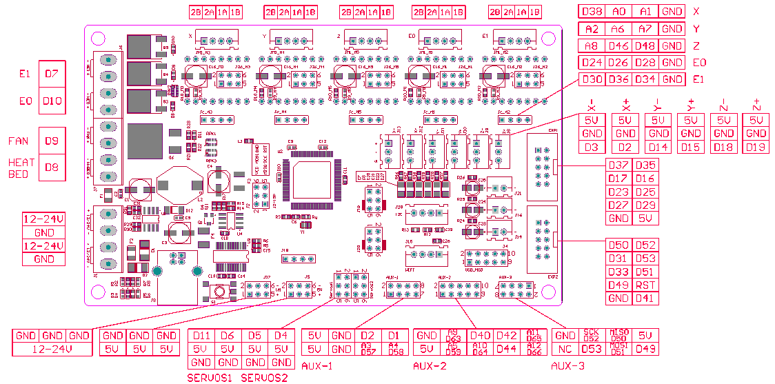
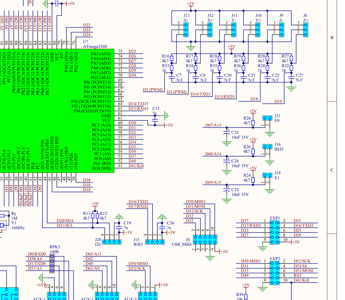
This post might help as it contains a schematic of the whole board. Is this where Analog 15/ Digital 69 is? Its Extruder 1 (ord the second installed extruder) temperature probe connection.
Here is a clearer picture of the board.
That E1 must be the termistor input. It isn’t labeled on the OP diagram (that I can see) and the parts hanging on it in Marion’s diagram make it look like a good input pin.
I’m not sure what else you’re asking besides the probe question. You want to have a relay for things like the spindle and laser, but you also want to control the laser with PWM? Controlling a relay with a spindle can be any pin (as long as the relay isn’t just a standalone relay). You would only toggle that occasionally. The Laser PWM would probably be better on a fan output pin, so you can toggle it with a mosfet instead of a relay. IIRC, grbl has the concept of a spindle on/off separate from the spindle speed control. So you can probably assign the first to any aux pin, and the second to one of the fans.
Thank you very much, both of you! I’ll give that pin a try later today. Marion, I really appreciate you digging into my issue tike that!
Jeffeb3, I AM controlling the laser through a TTY (sp?) pin, and it works fine. But I want to shut off the power supply when I’m not actually using the laser (or CNC). Not a fan of leaving the laser “active” when I’m not around. Right now, I physically unplug it when I leave. So having my laser process activate the relay to turn on power to the laser’s PSU as the first step in actually burning something would be a good next step, I think.
Same with the spindle. Right now, the spindle is “active” the whole time the CNC is in spindle mode, and I just turn the speed down to 0 with the potentiometer on the spindle’s PSU. Being able to leave the potentiometer at a particular setting and turning on the juice to the spindle’s PSU as part of the CNC process would clean up the process a bit, and it would leave the spindle “dead” at the end of the job. Ideally, I would have speed control as part of the GRBL commands, but not sure if that’s possible with the spindle PSU I’m using (cheap Chinese spindle direct from BangGood).
Best practice would have you using a zero crossing electronic switch rather than a relay to switch substantial loads on and off…but as you already have the relay array…
flood or mist coolant (M8/M7 on M9 off) would work well as a spindle/laser enable signal… the ESP32_GRBL use the same when employing PWM for the spindle/laser output signal…the only thing I would add is there is something comforting knowing the ultimate control over the spindle and laser output is a manual mechanical operation (the buck stops with the human!)
I love working from home, and having the freedom to run out the to gara-shop on my lunch break…
@scrounge79, I owe you a virtual beer! Plugged the probe into the E1 temperature plug, hit the “Probe” feature in CNCjs, and boom! Watched the z-axis come down, shorted the probe, and up it went. Perfect!
The IOT brick works great on the fan pins.
M106/107 with the attribute referring to which fan does a good job in starting and stopping it with my setup. How that maps to GRBL and the MKS 1.4, I don’t know, but I really like mine.
Yeah. I would probably use one of those arduino relay boards and any 5V pin to toggle them. Of course, you’ll ha e to figure out the number to call it in the firmware.