Gpio.27 and gpio.26 are bad now

Jackpot board lasertree k30 spindle getting power and ground parallel to the control board, not through the mosfets.

Laser would not turn off before so I switched to using gpio.26 in the config and it worked, now can’t get the laser to turn on at all, no lights at gpio.26 or 27 when it should be sending pwm. Should I be able to see anything?
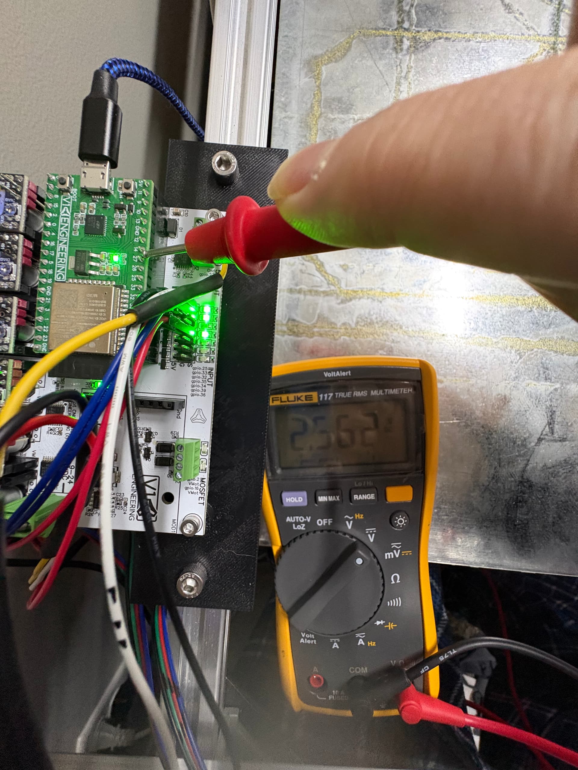
I’ll put a voltmeter on the laser to see if it’s ok too

Laser won’t turn on at all now. Reflowed solder on gpio.27

Tested gpio.27 and 26, no dc voltage being output when the laser is supposed to be on

Can you put up a picture or draw a little diagram.

What jackpot version?

Nothing on 27 or 26 when the laser should be running.

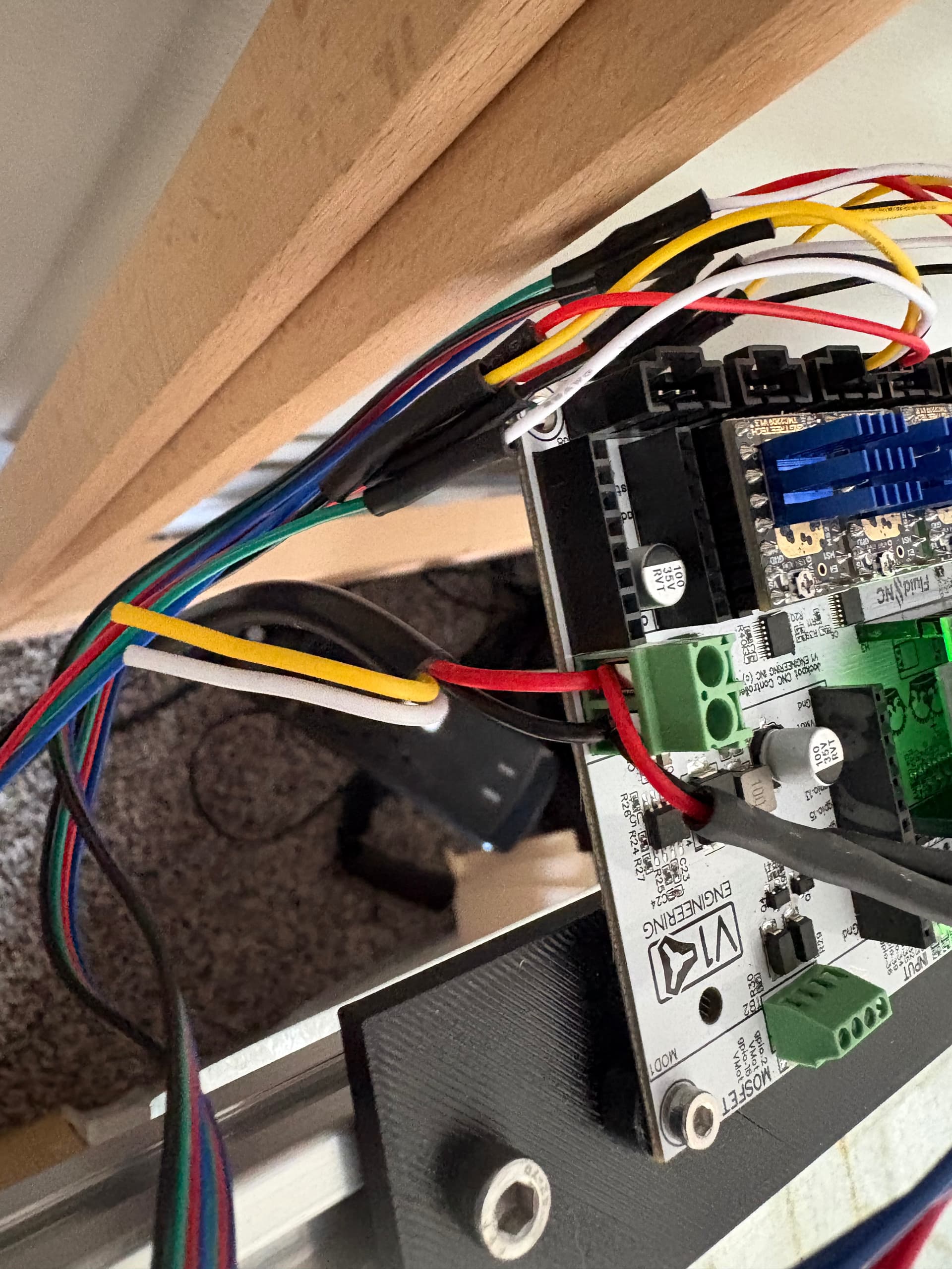
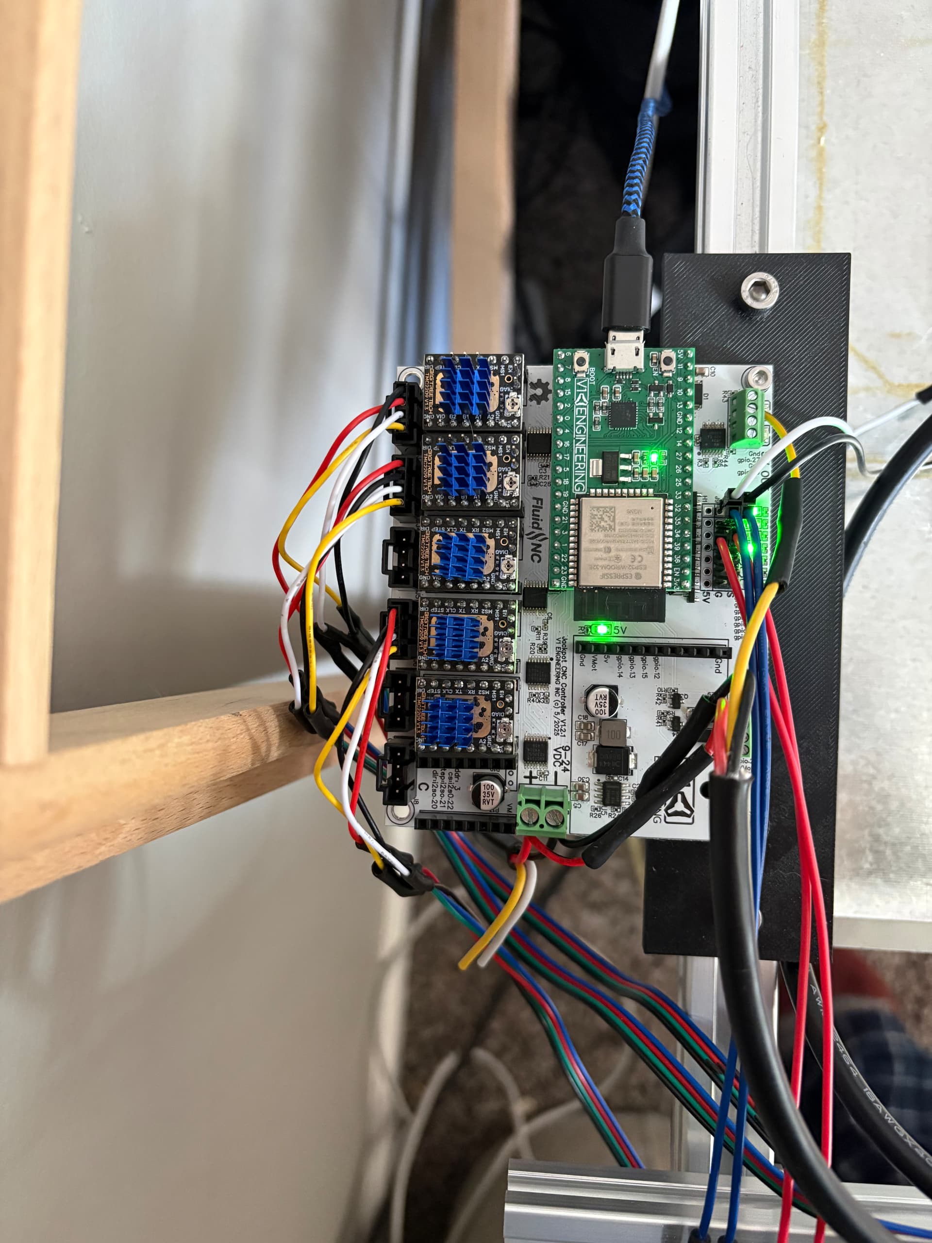
That doesn’t really show how you’ve connected the laser electrically. There’s nothing connected to 26 or 27 in that picure. We want to know where you tied the returns together for the various components.

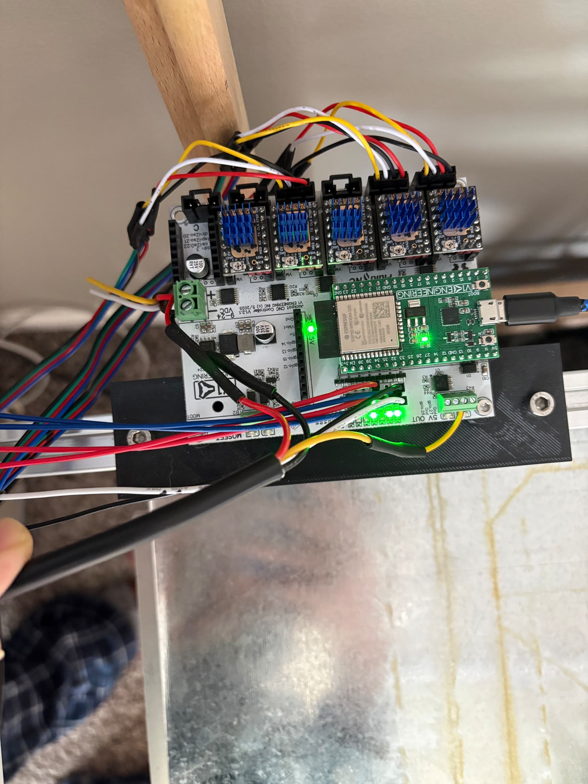
Side note- you want to keep wiring well clear of the antenna on the ESP-32. What’s shown in the picture will cause wireless signal integrity issues if you use WiFi. If not, carry on.

Oh, the yellow cable goes usually to 27, but it kept the laser on all the time, so I switched it to 26 and changed the yaml, but now it doesn’t function on either one

Where do you connect/tie returns?

We need either a picture or a schematic of how you’ve hooked this up. Just connecting a single yellow wire will not work correctly in many/most cases.

Edit to add: For a similar reason, we should ask “How are you testing?”
If you’re going to measure GPIO 26 or GPIO 27 on that jackpot, the DMM needs to have the return tied to the (-) lead of VMOT. If there’s no voltage there when there previously was, then you may have blown one or more GPIOs on that ESP-32.

Knowing how that return is hooked up or not will help us try to understand what is wrong with your system.

If that’s obvious to you, no offense intended- we can’t tell what level of experience our community members have from a forum post.

Using a diode laser also requires changes to the config.yaml so you could post that too to check.

Yaml is very picky - an extra space at the beginning or end of lines can break things.

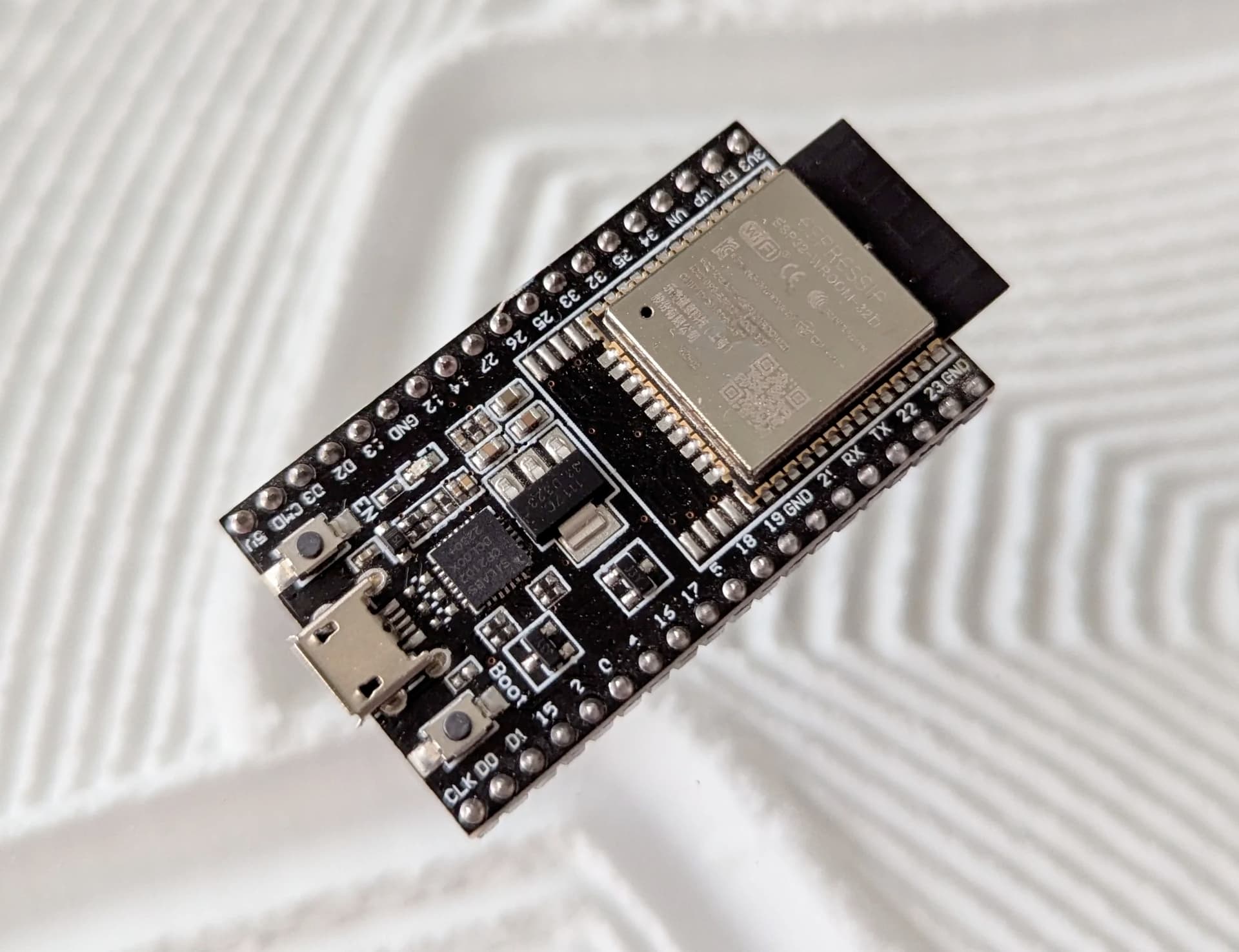
What returns? Lasers have a 3 wire connection. Power, ground, and pwm signal for laser intensity. Not trying to be argumentative I’m just an idiot and don’t know what you’re are referring to. I’ll copy the config in here when I get a chance. I suspect the esp32 as well, I’m getting an espressif to swap and see

I’m testing with a fluke meter, tested power coming into the unit at the board pos and neg ports, getting 24.1v dc. Tested at vmot and same ground, getting 24.1v tested 5v out pins, getting 5v dc.
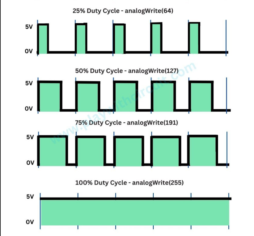
I’ll take pics of the tests as I do them. With laser power set to 80%, I should be seeing something near 4v on gpio.27 should I not?

No. The laser is using PWM,not an analogue voltage.

The frequency of the pulses aren’t going to be readable on a voltage meter but the output will only be 5v 80% of the time. You’d need an oscilloscope to view the signal voltage changes

1 Like

Should the leds on those pins be lit tho? Ok taking pictures now

Board pics


Yaml


board: Jackpot1 TMC2209
name: Pteranodon
meta: 11-8-2025
planner_blocks: 32
stepping:
  engine: I2S_STATIC
  idle_ms: 255
  pulse_us: 2
  dir_delay_us: 1
  disable_delay_us: 0
uart1:
  txd_pin: gpio.0
  rxd_pin: gpio.4
  rts_pin: NO_PIN
  baud: 115200
  mode: 8N1
axes:
  shared_stepper_disable_pin: NO_PIN
  x:
    steps_per_mm: 40
    max_rate_mm_per_min: 50000
    acceleration_mm_per_sec2: 200
    max_travel_mm: 1778
    soft_limits: false
    homing:
      cycle: 2
      positive_direction: false
      mpos_mm: 0
      feed_mm_per_min: 300
      seek_mm_per_min: 3000
      settle_ms: 500
      seek_scaler: 5
      feed_scaler: 5
    motor0:
      limit_neg_pin: gpio.25
      limit_pos_pin: NO_PIN
      limit_all_pin: NO_PIN
      hard_limits: false
      pulloff_mm: 4
      tmc_2209:
        uart_num: 1
        addr: 0
        cs_pin: NO_PIN
        r_sense_ohms: 0.11
        run_amps: 0.8
        homing_amps: 0.8
        hold_amps: 0.7
        microsteps: 8
        stallguard: 0
        stallguard_debug: false
        toff_disable: 0
        toff_stealthchop: 5
        toff_coolstep: 3
        run_mode: StealthChop
        homing_mode: StealthChop
        use_enable: false
        direction_pin: i2so.1
        step_pin: i2so.2
        disable_pin: I2SO.0
  y:
    steps_per_mm: 40
    max_rate_mm_per_min: 50000
    acceleration_mm_per_sec2: 200
    max_travel_mm: 1702
    soft_limits: false
    homing:
      cycle: 2
      positive_direction: false
      mpos_mm: 0
      feed_mm_per_min: 300
      seek_mm_per_min: 3000
      settle_ms: 500
      seek_scaler: 5
      feed_scaler: 5
    motor0:
      limit_neg_pin: gpio.33
      limit_pos_pin: NO_PIN
      limit_all_pin: NO_PIN
      hard_limits: false
      pulloff_mm: 4
      tmc_2209:
        uart_num: 1
        addr: 1
        cs_pin: NO_PIN
        r_sense_ohms: 0.11
        run_amps: 0.8
        homing_amps: 0.8
        hold_amps: 0.7
        microsteps: 8
        stallguard: 0
        stallguard_debug: false
        toff_disable: 0
        toff_stealthchop: 5
        toff_coolstep: 3
        run_mode: StealthChop
        homing_mode: StealthChop
        use_enable: false
        step_pin: i2so.5
        direction_pin: i2so.4
        disable_pin: I2SO.7
    motor1:
      limit_neg_pin: gpio.35
      limit_pos_pin: NO_PIN
      limit_all_pin: NO_PIN
      hard_limits: false
      pulloff_mm: 4
      tmc_2209:
        uart_num: 1
        addr: 3
        cs_pin: i2so.14
        r_sense_ohms: 0.11
        run_amps: 0.8
        homing_amps: 0.8
        hold_amps: 0.7
        microsteps: 8
        stallguard: 0
        stallguard_debug: false
        toff_disable: 0
        toff_stealthchop: 5
        toff_coolstep: 3
        run_mode: StealthChop
        homing_mode: StealthChop
        use_enable: false
        step_pin: i2so.13
        direction_pin: i2so.12
        disable_pin: I2SO.15
  z:
    steps_per_mm: 200
    max_rate_mm_per_min: 1800
    acceleration_mm_per_sec2: 80
    max_travel_mm: 300
    soft_limits: false
    homing:
      cycle: 1
      positive_direction: true
      mpos_mm: 0
      feed_mm_per_min: 200
      seek_mm_per_min: 800
      settle_ms: 500
      seek_scaler: 1.1
      feed_scaler: 1.1
    motor0:
      limit_neg_pin: NO_PIN
      limit_pos_pin: NO_PIN
      limit_all_pin: NO_PIN
      hard_limits: false
      pulloff_mm: 4
      tmc_2209:
        uart_num: 1
        addr: 2
        cs_pin: NO_PIN
        r_sense_ohms: 0.11
        run_amps: 0.8
        homing_amps: 0.8
        hold_amps: 0.7
        microsteps: 8
        stallguard: 0
        stallguard_debug: false
        toff_disable: 0
        toff_stealthchop: 5
        toff_coolstep: 3
        run_mode: StealthChop
        homing_mode: StealthChop
        use_enable: false
        step_pin: i2so.10
        direction_pin: i2so.9
        disable_pin: I2SO.8
    motor1:
      limit_neg_pin: NO_PIN
      limit_pos_pin: gpio.34
      limit_all_pin: NO_PIN
      hard_limits: false
      pulloff_mm: 4
      tmc_2209:
        uart_num: 1
        addr: 3
        cs_pin: i2so.19
        r_sense_ohms: 0.11
        run_amps: 0.8
        homing_amps: 0.8
        hold_amps: 0.7
        microsteps: 8
        stallguard: 0
        stallguard_debug: false
        toff_disable: 0
        toff_stealthchop: 5
        toff_coolstep: 3
        run_mode: StealthChop
        homing_mode: StealthChop
        use_enable: false
        step_pin: i2so.18
        direction_pin: i2so.17
        disable_pin: I2SO.16
i2so:
  bck_pin: gpio.22
  data_pin: gpio.21
  ws_pin: gpio.17
start:
  must_home: false
coolant:
  flood_pin: gpio.2
  mist_pin: gpio.16
  delay_ms: 0
macros: {}
user_outputs:
  analog0_pin: NO_PIN
  analog1_pin: NO_PIN
  analog2_pin: NO_PIN
  analog3_pin: NO_PIN
  analog0_hz: 5000
  analog1_hz: 5000
  analog2_hz: 5000
  analog3_hz: 5000
  digital0_pin: gpio.26
  digital1_pin: NO_PIN
  digital2_pin: NO_PIN
  digital3_pin: NO_PIN
Laser:
  pwm_hz: 5000
  output_pin: gpio.27
  enable_pin: NO_PIN
  disable_with_s0: false
  s0_with_disable: true
  tool_num: 0
  speed_map: 0=0.000% 1000=100.000%
  off_on_alarm: true

Many laser modules (not all) use 3-wire connections. The terms ground and return can be somewhat interchanged here, but the devil is always in the details.

Is your laser run from the same power supply that powers your Jackpot or do you have different VMOT and Laser power supplies?

If you have two power supplies, the returns (grounds) of the two power supplies have to be directly tied together.

The meter will measure something, but depending on how the meter averages the PWM signal may or may not give you good measurements.

What command are you using to set that laser power?

You’ve set the speed map to be 0 to 1000. To set the power to 80% you should be sending S800.

If you’ve configured your sender or control to expect a map of 0-255, then you’d be sending S204, which in your map would be only 20% output power. (Some lasers may not even light up at that level, though most would).

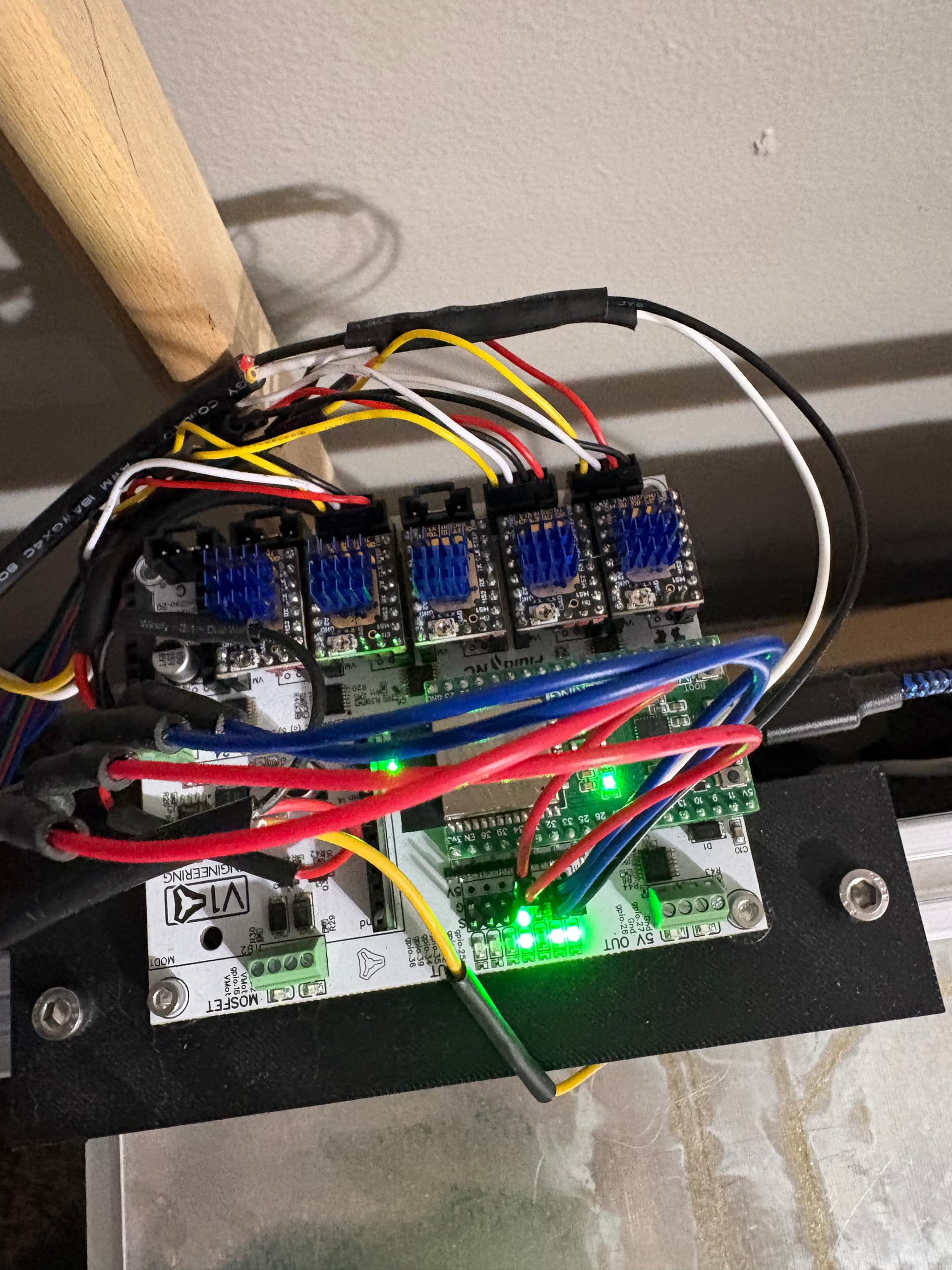
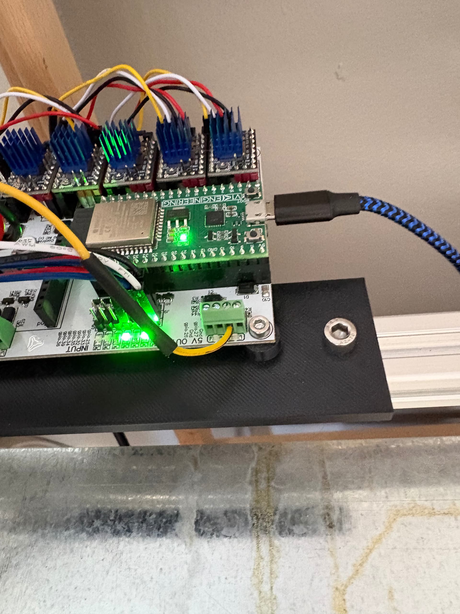
In Lightburn it’s set the same, 0-1000, Lightburn is sending 80% power. Shouldn’t the led at gpio.27 be lighting up when it’s trying to send a signal? It’s staying off when the laser should be emitting. So the laser isn’t emitting. The ground for the laser is going to the power supply ground, connected in parallel at the negative terminal of the board, the positive is connected to the power supply positive at the positive terminal of the board. The yellow signal wire is connected to the 27 pin. You can see it in the pictures.

It was working fine and then it stopped. No changes, nothing else weird, just stopped. I’m going to see what happens if I connect direct 5v to the signal and see if the laser goes from that to at least verify the laser isn’t the issue

That is one reason I’ve asked a bunch of questions about return connections, as breaking the current path would cause it to stop.

Did it do that before? Those outputs are buffered. For a PWM signal I’d expect them to flicker if you’re rastering or light up if vector with the laser.

There’s a chip between the ESP-32 and the output.

I’m curious what you measure with the DMM if you go back directly to the GPIO 27 pin on the ESP-32.

Depending on which one you have, it should be clearly labeled as “27”

Or, if you have the V1 ESP-32