I don’t right now. I need to find a new source for the endstops. I had the previous ones made with split wires for ease of use.
If you want to grab the rest of the stuff from the shop I should have a few previously loved ones I can throw in.
I don’t right now. I need to find a new source for the endstops. I had the previous ones made with split wires for ease of use.
If you want to grab the rest of the stuff from the shop I should have a few previously loved ones I can throw in.
Would these work for the end stops?
Also, I bought one of the boards. Do they come with Fluid NC installed?
I suggest you use mechanical endstops because the optical ones get dirty easily with chips, I used these and everything works fine:
Another option…
Requires firmware changes, am not clear on pros and cons. No moving parts that can break off seems nice.
We do not use these on the ZenXY because you can hear them clicking for hours on end.
The only issue I see is size, most are fairly large but if you can find small enough ones they would be great, actually.
I think so I need to take a closer look a little later.
I thought the end stops are only used for homing?
I’m assuming that the board you are selling has firmware installed. Is it the WIFI version. If this is correct, I should be able to power it and connect from my phone or laptop?
On a Zen you tend to use every available mm so your mechanical switches will continually click.
Has the webui been updated to save changes yet by chance ?
It’s been a while since I have jumped back into getting my fluidnc board to home.
Welllll… I think its finally time to resurrect this thread. Only had the parts kit laying around for over a year ![]() I have finally drawn up what I want to use it in and now I am to the point I want to build it.
I have finally drawn up what I want to use it in and now I am to the point I want to build it.
Don’t laugh at my unfinished cad but here is the idea…
The plan is a “test table” to run my prebuilt LR4’s on before they get packaged to ship, and what would be better for pics and such than having a nice Zen table in the middle with LEDs and such???
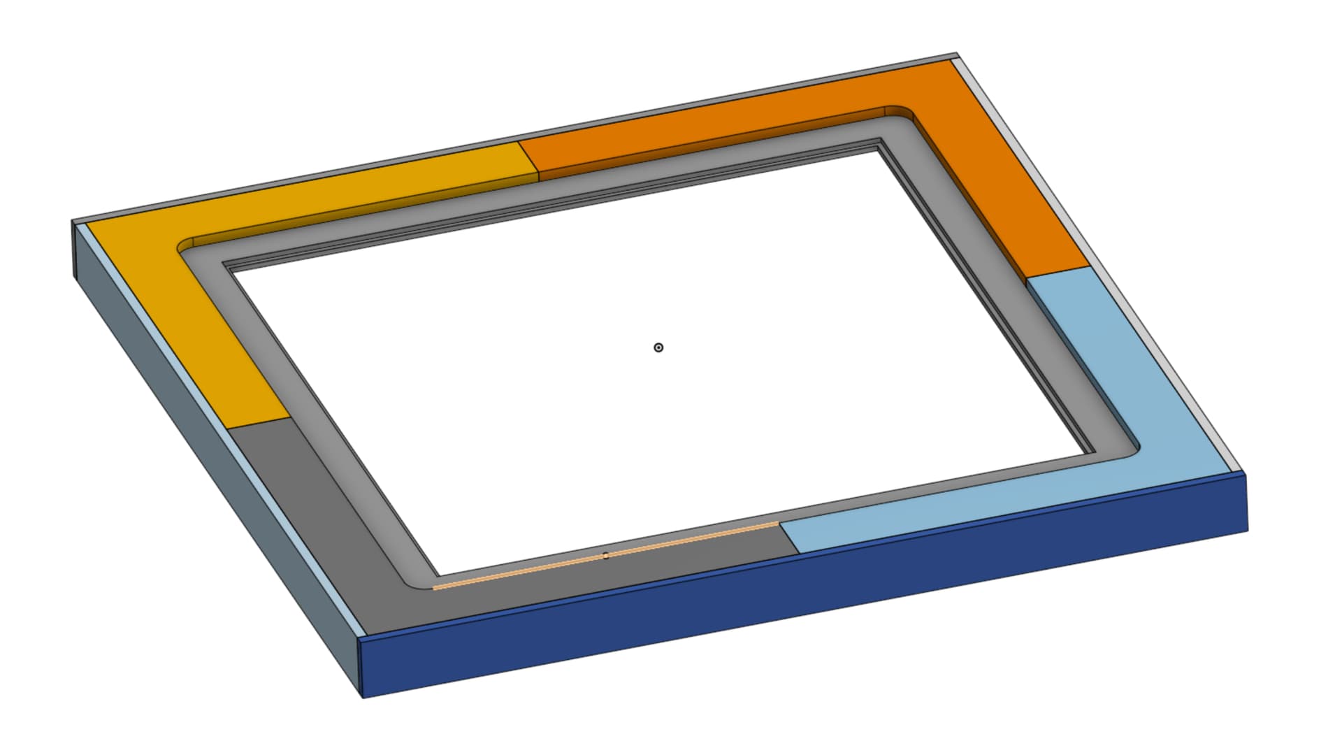
The idea is the Zen will be part of the table top, with the cabinet bases notched out to allow room for the actual Zen. I also went with the layered approach stolen from @jeffeb3’s awesome Zen table for RMRRF
The 4 separate parts are for the “LED Layer” and keep the LEDs (hopefully) back far enough to keep the actual LED’s invisible. And being the 4 separate parts they don’t waste near as much material.
I think my largest concern right now is do I have enough room under the frame for the actual Zen machine.
Hopefully I have shown enough to give the idea of what I am trying to build without wasting anyone’s time. If you see anything that looks dumb or wont work don’t hesitate to point it out before I pull the trigger and start wasting material lol. Ohh and I forgot to say earlier that I have 2 sheets of 1/4" Acrylic (I think, might be polycarbonate, I cant remember right now and too lazy to go look) one for the top and the second for the base to put the baking soda on.
Easiest just to build the Zen and take some measurements. It is nice to really squeeze it in and leave as little extra room. Sucks the CAD is gone.
Yeah. I had all the parts printed but who knows where they are now. New set on the printer now. Will assemble and double check all my measurements before I start cutting plywood.
Is what it is now. Good thing is when you update to V3, it will be in onshape and easy to get ![]()
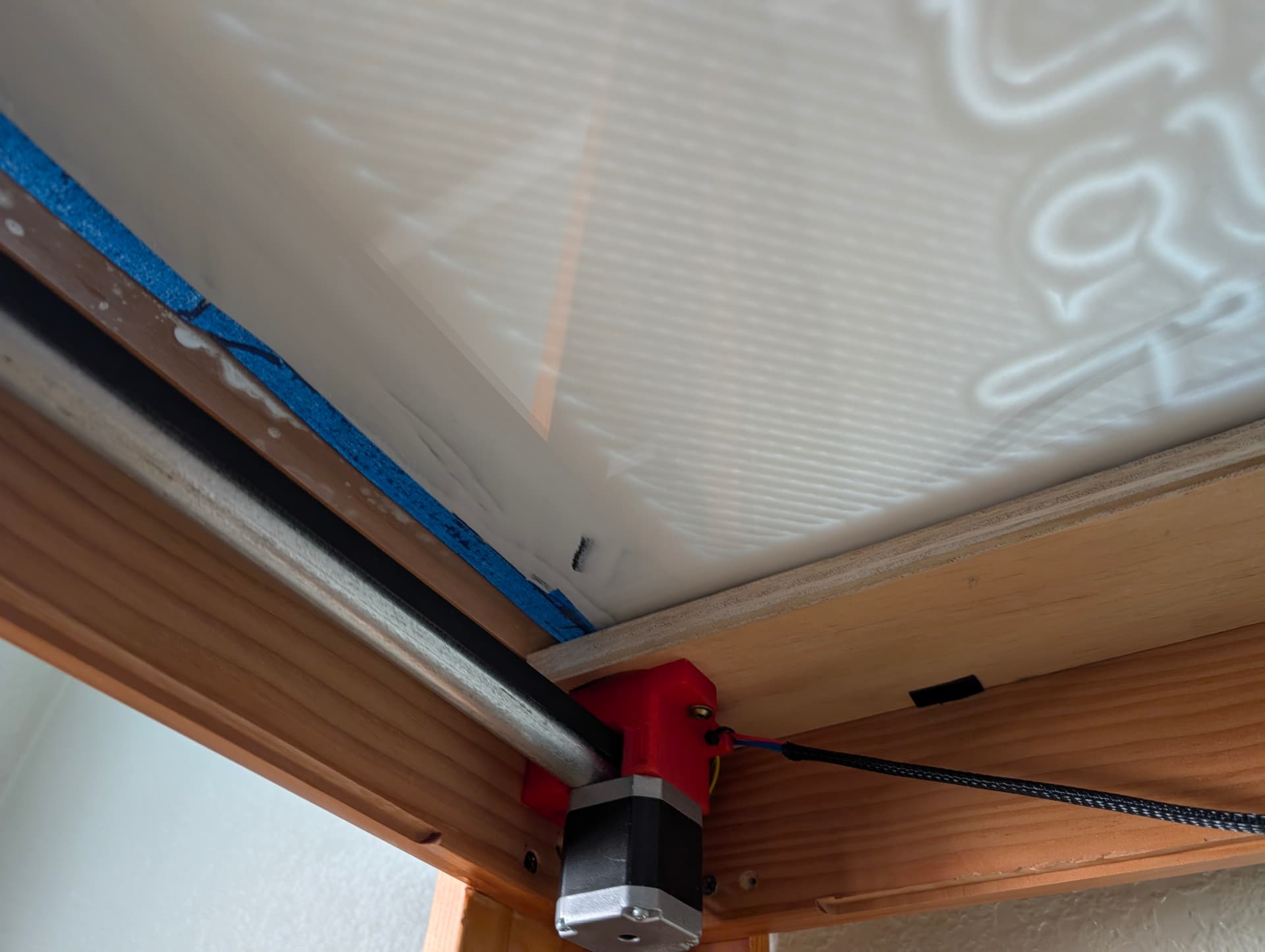
Made a little progress finally. Got the conduit cut and everything assembled minus the belts. I’ve had the kit for this thing for so long that I lost some of the hardware. M5 nuts and M3 screws were no where to be found, but had everything else and thankfully spares of the needed hardware.
Now I need to get off my butt and build the table top (and the rest of the table) so I can actually get it mounted and figure out how to run it lol. Picking up the needed plywood tomorrow so that’s a step in the right direction!
HOPEFULLY before I head back offshore next week I’ll have some pics to post of it at least mounted to the table top lol
OK… Hit a snag… ![]()
Was setting up my CAM to cut out my table parts, just needed to measure the thickness of my acrylic when I realized my CAD was all wrong for the size acrylic I bought ![]()
No big deal. I wanted to clean up the CAD a little anyways so I just redrew it. Good practice.
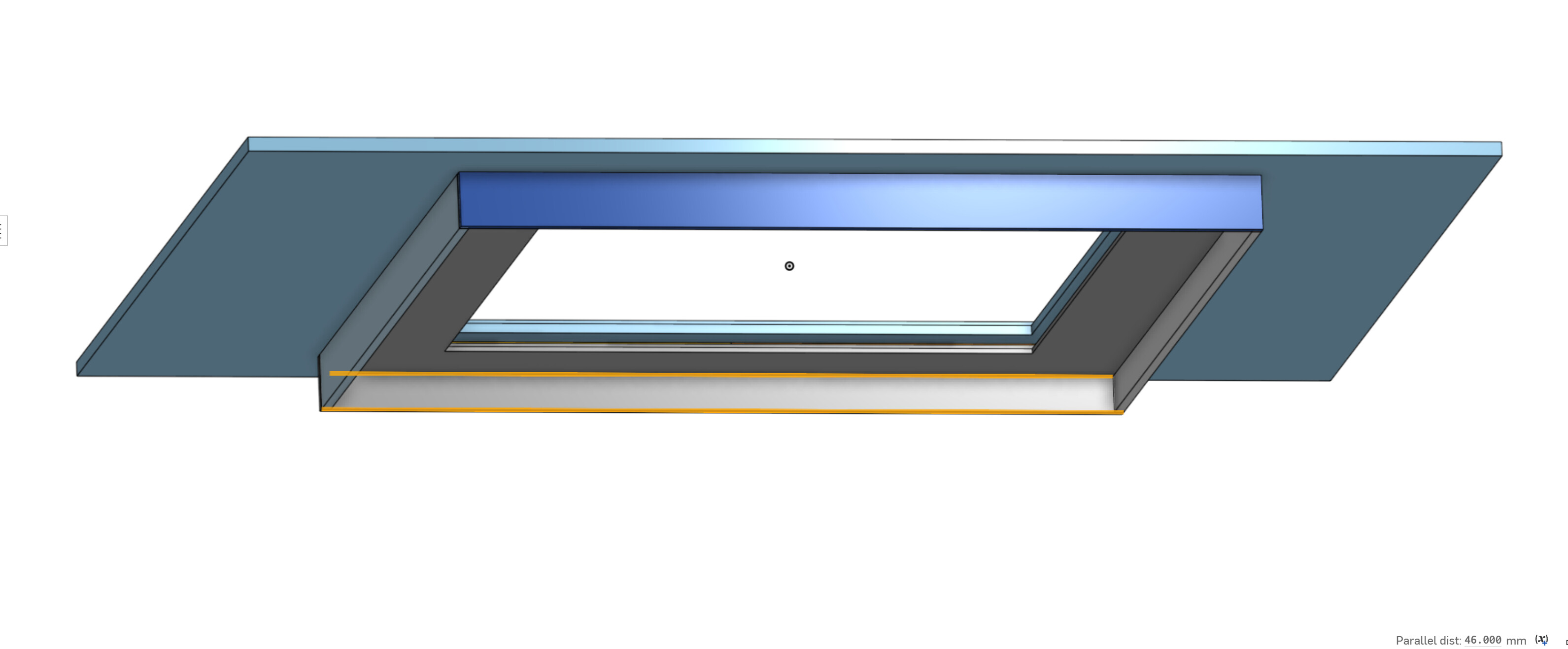
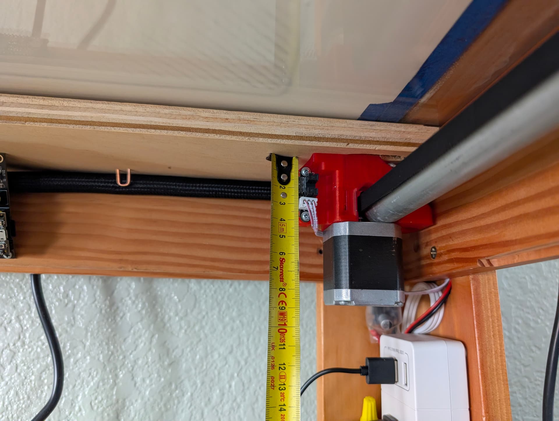
Now before I go and cut all this I am hoping some of y’all can take a look real quick and make sure what I have planned will work. I am worried I wont have enough clearance, but I don’t want to make the drop down larger than needed either. I decided to do away with the drawers and will just build some doors for the base cabinets later. Right now I have the thickness of the layers below the top measured at 32mm ( I need to go verify the thickness of the MDF and 1/2" birch to make sure that is correct). Is 68mm enough room below that? I know the Docs say 66mm, but I also know Ryan doesn’t give much (any) wiggle room for that stuff either. So I am hoping one of you that have successfully built one of these will know if its enough or not lol.
Also the Docs don’t show anything about how to attach this thing to the table. I see the screw holes in the parts so I am assuming I can just attach it right to the bottom of my bottom layer of MDF that holds the bottom acrylic?? Is that lip to hold the acrylic too thick where I need spacers?
@vicious1 @jeffeb3 or anyone else have any pearls of wisdom before I pull the trigger and waste a bunch of plywood/MDF?
Here is a link to the CAD in Onshape. Don’t judge too much please.
Also…
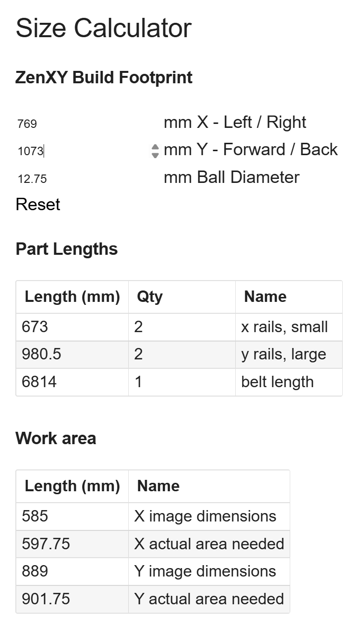
I fiddle with the calculator numbers to make the Image Dimensions equal to what I have open on the acrylic inside of the “lip” to hold the acrylic. Does this look correct? Or do I need to give a little more wiggle room?
Yup screws with fender washers.
Not sure what you are asking for, but I have mine set for minimum and planned on cutting holes for the steppers to poke through.
My glass goes all the way to the outside of the frame that is why I do not have any side screws of fender washers…or even a frame for that matter, But it also means I stacked two magnets to get that extra 1/2".
The dimensions it gives should be the exact outside path of the ball that is why it asks for the ball diameter, you will need to add a lip of your own.
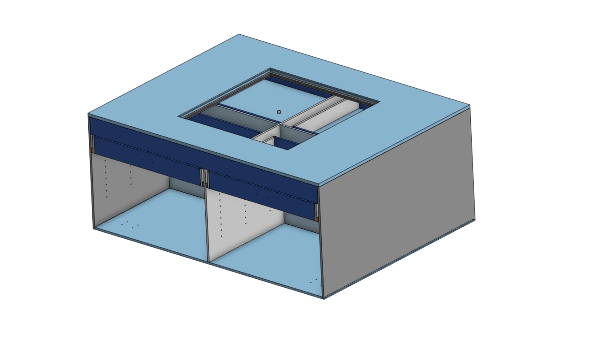
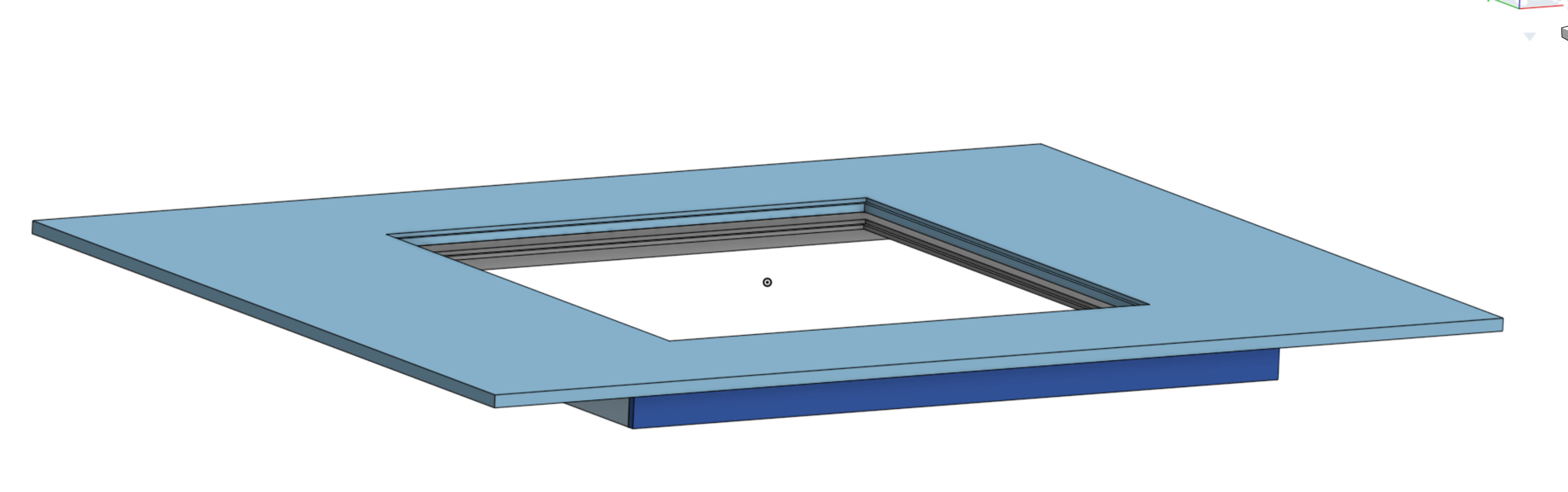
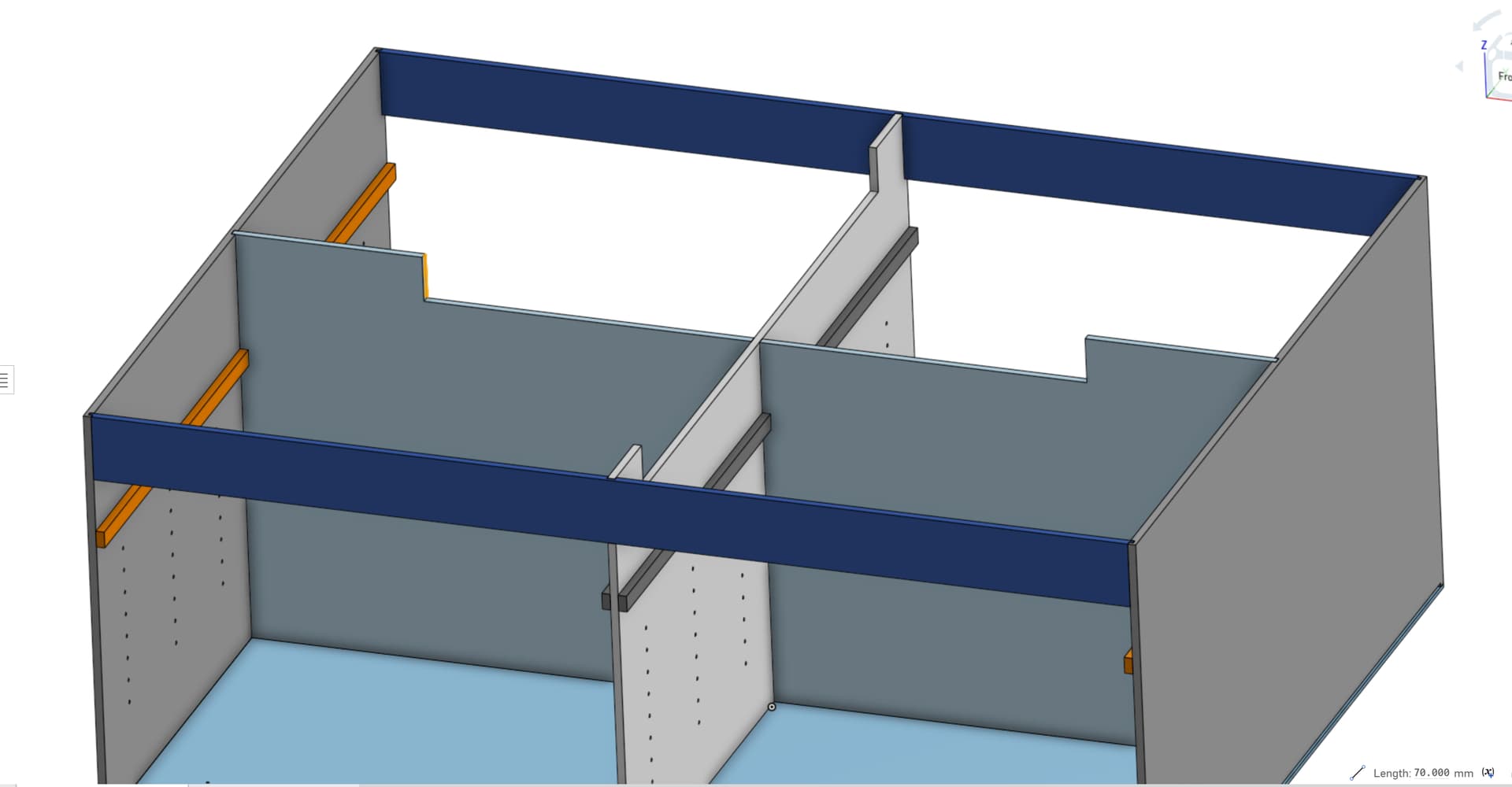
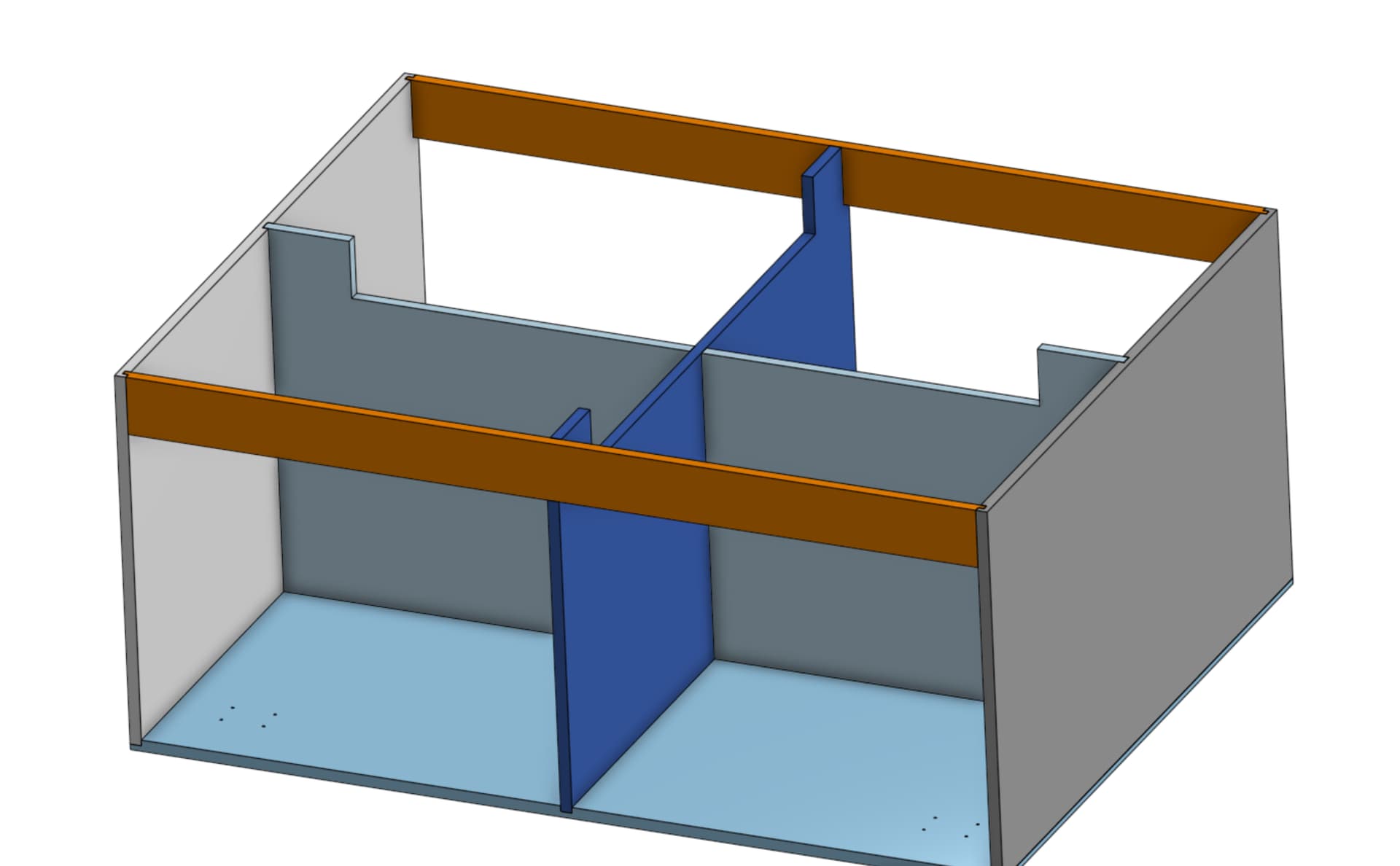
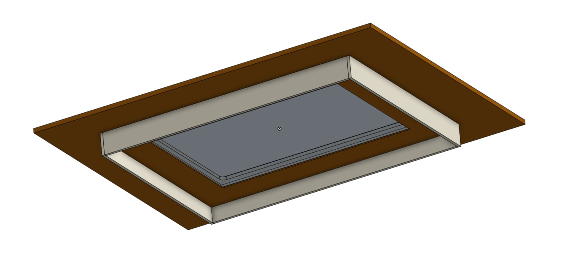
With the way this table top is on top of cabinets instead of just a normal table like you have, I have to create clearance underneath. That was why I added the CAD for it but here are some screen shots that hopefully will help explain it better…
The square “notch” cut in the top of the cabinet middle/back is for the Zen to have clearance. The top (second pic) sits down into the cabinets. That’s why I need to make sure my notch is low enough and the sides coming down from the top are long enough to give the motion system clearance to move without hitting. I am fine with the motors sticking down lower as they don’t move and are in the clear as far as the cabinets are concerned. Hopefully this makes more sense now.
Sweet. That’s what I was assuming, but we all know what happens when you assume ![]()
as of right now I will be up 4mm. So hopefully I can just space the magnet up that high and be ok.
While waiting for the confromation info that @vicious1 was able to provide, I dug out the Pen/Laser board that I ordered way too long ago to remember when ![]()
Figured out that it didnt have an ESP32 on it already, but found one of the USB C ones I ordered from Ryan forever ago and stuck that on there.
Took some doing to get the config file right. The example one listed on the wiki isnt correct anymore. But I “think” I have it close now.
Config.yaml…
name: "LR4 Test Table ZenXY"
board: "FluidNC Pen/Laser 2209"

stepping:
  engine: RMT
  idle_ms: 255
  dir_delay_us: 1
  pulse_us: 2
  disable_delay_us: 0

kinematics:
  corexy:

uart1:
  txd_pin: gpio.17
  rxd_pin: gpio.16
  rts_pin: NO_PIN
  cts_pin: NO_PIN
  baud: 115200
  mode: 8N1

axes:
  shared_stepper_disable_pin: gpio.13:high

  x:
    steps_per_mm: 200
    max_rate_mm_per_min: 8000
    acceleration_mm_per_sec2: 300
    max_travel_mm: 598
    soft_limits: false
    homing:
      cycle: 2
      positive_direction: false
      mpos_mm: 25.000
      feed_mm_per_min: 500.000
      seek_mm_per_min: 1000.000
      settle_ms: 500
      seek_scaler: 1.100
      feed_scaler: 1.100

    motor0:
      limit_neg_pin: gpio.36:low
      #Diag pin is gpio.34
      tmc_2209:
        uart_num: 1
        addr: 0
        r_sense_ohms: 0.110
        run_amps: 0.250
        hold_amps: 0.250
        microsteps: 32
        stallguard: 0
        stallguard_debug: false
        toff_disable: 0
        toff_stealthchop: 5
        toff_coolstep: 3
        run_mode: StealthChop
        homing_mode: StealthChop
        use_enable: false
        direction_pin: gpio.12
        step_pin: gpio.14
        disable_pin: NO_PIN


    motor1:
      null_motor:

  y:
    steps_per_mm: 200
    max_rate_mm_per_min: 8000
    acceleration_mm_per_sec2: 300
    max_travel_mm: 902
    soft_limits: false
    homing:
      cycle: 1
      positive_direction: false
      mpos_mm: 0.000
      feed_mm_per_min: 100.000
      seek_mm_per_min: 200.000
      settle_ms: 500
      seek_scaler: 1.100
      feed_scaler: 1.100

    motor0:
      limit_neg_pin: gpio.39:low
      #diag pin is gpio.35
      tmc_2209:
        uart_num: 1
        addr: 1
        r_sense_ohms: 0.110
        run_amps: 0.250
        hold_amps: 0.250
        microsteps: 32
        stallguard: 0
        stallguard_debug: false
        toff_disable: 0
        toff_stealthchop: 5
        toff_coolstep: 3
        run_mode: StealthChop
        homing_mode: StealthChop
        use_enable: false
        direction_pin: gpio.26
        step_pin: gpio.25
        disable_pin: NO_PIN
    motor1:
      null_motor:

spi:
  miso_pin: gpio.19
  mosi_pin: gpio.23
  sck_pin: gpio.18

sdcard:
  cs_pin: gpio.5
  card_detect_pin: NO_PIN
$SS Output…
rst:0x1 (POWERON_RESET),boot:0x17 (SPI_FAST_FLASH_BOOT)
configsip: 0, SPIWP:0xee
clk_drv:0x00,q_drv:0x00,d_drv:0x00,cs0_drv:0x00,hd_drv:0x00,wp_drv:0x00
mode:DIO, clock div:1
load:0x3fff0030,len:1184
load:0x40078000,len:13260
load:0x40080400,len:3028
entry 0x400805e4
[MSG:INFO: uart_channel0 created]
[MSG:RST]
[MSG:INFO: FluidNC v3.9.4 https://github.com/bdring/FluidNC]
[MSG:INFO: Compiled with ESP32 SDK:v4.4.7-dirty]
[MSG:INFO: Local filesystem type is littlefs]
[MSG:INFO: Configuration file:config.yaml]
[MSG:WARN: X Axis tmc_2209 homing current not in config. Using run current]
[MSG:WARN: Y Axis tmc_2209 homing current not in config. Using run current]
[MSG:INFO: Machine LR4 Test Table ZenXY]
[MSG:INFO: Board FluidNC Pen/Laser 2209]
[MSG:INFO: UART1 Tx:gpio.17 Rx:gpio.16 RTS:NO_PIN Baud:115200]
[MSG:INFO: SPI SCK:gpio.18 MOSI:gpio.23 MISO:gpio.19]
[MSG:INFO: SD Card cs_pin:gpio.5 detect:NO_PIN freq:8000000]
[MSG:INFO: Stepping:RMT Pulse:2us Dsbl Delay:0us Dir Delay:1us Idle Delay:255ms]
[MSG:INFO: Axis count 3]
[MSG:INFO: Shared stepper disable gpio.13]
[MSG:INFO: Axis X (25.000,623.000)]
[MSG:INFO:   Motor0]
[MSG:INFO:     tmc_2209 UART1 Addr:0 CS:NO_PIN Step:gpio.14 Dir:gpio.12 Disable:NO_PIN R:0.110]
[MSG:INFO:  X Neg Limit gpio.36:low]
[MSG:INFO:   Motor1]
[MSG:INFO: Axis Y (0.000,902.000)]
[MSG:INFO:   Motor0]
[MSG:INFO:     tmc_2209 UART1 Addr:1 CS:NO_PIN Step:gpio.25 Dir:gpio.26 Disable:NO_PIN R:0.110]
[MSG:INFO:  Y Neg Limit gpio.39:low]
[MSG:INFO:   Motor1]
[MSG:INFO: Axis Z (-1000.000,0.000)]
[MSG:INFO:   Motor0]
[MSG:ERR: X Axis TMC driver not detected - expected 0x21 got 0x0]
[MSG:ERR: Y Axis TMC driver not detected - expected 0x21 got 0x0]
[MSG:INFO: Kinematic system: CoreXY]
[MSG:INFO: Connecting to STA SSID:Jones]
[MSG:INFO: Connecting.]
[MSG:INFO: Connecting..]
[MSG:INFO: Connected - IP is 192.168.68.119]
[MSG:INFO: WiFi on]
[MSG:INFO: Start mDNS with hostname:http://ZEN.local/]
[MSG:INFO: HTTP started on port 80]
[MSG:INFO: Telnet started on port 23]

Grbl 3.9 [FluidNC v3.9.4 (wifi) '$' for help]
[MSG:INFO: ALARM: Unhomed]
ALARM:14
ok
[VER:3.9 FluidNC v3.9.4:]
[OPT:PHS]
[MSG:Machine: LR4 Test Table ZenXY]
[MSG:Mode=STA:SSID=Jones:Status=Connected:IP=192.168.68.119:MAC=08-D1-F9-A4-F8-E4]
ok
I don’t have any motors or anything hooked up to the board yet so I am hoping that is why I am getting
[MSG:ERR: X Axis TMC driver not detected - expected 0x21 got 0x0]
[MSG:ERR: Y Axis TMC driver not detected - expected 0x21 got 0x0]
70mm should be plenty
I should be REAL close to that.
The more I sit here and think about it, I think I am going to cut out all the parts for the table top first. And assemble it all. That way I can have it mounted and verify that it will clear before I cut the parts for the cabinet. Worst case I will have to add to or replace the 4 side parts on the top, but everything else will be good to go and I wont have to also manually notch the bottom cabinets.
Pretty sure you suggested that to me already and I just didn’t put 2 and 2 together in my head ![]()
![]()
We have an afternoon rain storm brewing right now. Hopefully in the next hour the temp out in the garage will be MUCH lower and I’ll still have the motivation to go out and cut a few parts ![]()
Yea, that’s been a bit. You can’t even get that version anymore. The new version has the built-in ESP32.