I like ncviewer. I noticed it has a decimal place error in the DRO. I couldn’t find where the source code was to fix it. I sure wish I had time to work on a tool like that.
Looks like they are putting step files back in. Nice interview with a high - up on the fusion team.

They’ve lost trust now. How long before they decide to pull features again?
2 Likes
Everything changes over October 1st.
I used to love f360 because the original AutoCAD was what I learned how to draft on but for the past 3 years or so I’ve been using rhino just because I had to learn it for a job and I just spent about an hour creating a new post processor for RhinoCam for the lowrider.
I know rhino is not free however if anyone wants the post processor I can share.
I tried freecad and the fact that I cannot use the keyboard to type in coordinates (or at least I haven’t figured out how to yet) is very frustrating.
1 Like
Not sure, but there is a Python console for automating some stuff
I’m glad Lars is back to making videos. His stuff is the best.
1 Like
Stupid question probably, but have the FS 360 changes started yet?
Rob
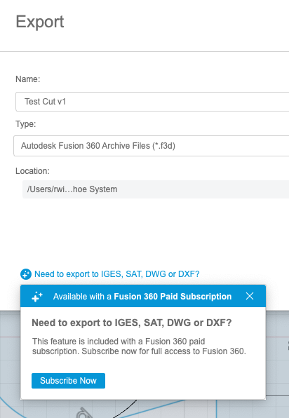
Some of it started oct 1. It looks like some export options are available until January. Step export was added back in indefinitely.
DXF export now gone.
For only the second time I wanted to use DXF export, just knocked a diagram up, tried to export it and it’s not there,
Oh well, not the world worst problem today.
Rob
1 Like
I believe dxf is still available to save from an individual schematic. You just can’t export the entire project.
Right click on one of the schematics and ‘save as dxf’ should still be there.
3 Likes
2 Likes
Is anyone still using Fusion for CAD?
According to the Milling Basics page,
Fusion’s free plan no longer supports more than one speed, so the feedrate for XY turn into very fast Z movements. More details in the forum.
Is this still an issue? I’ve been wanting to learn how to use fusion for CAD but I don’t want a 8mm/s plunge. Haha.
1 Like
Pretty much, yeah. Applies to the free version only.
Personally I find Fusion a bit too complex for my needs but I don’t see any reason you can’t use it for CAD and use a different program for CAM to eliminate the issue of only being able to set one speed.
I still use Fusion and the fast Z movement is still an issue that need to be worked around. My solution for the fast Z movements is to use an M203 g-code to set the maximum feedrate for Z. This setting can be saved using an M500 g-code, so it only has to be run once, or there are ways of a automatically inserting this g-code in every g-code file. Note that M203 uses mm/s where the feedrate used in other g-code is mm/min. The real loss by the Fusion 360 changes is rapid movements are removed, so some cutting can take more time.
1 Like
I need to craft a decent sed command for changing the Z rate 
1 Like
David,
Shout if you want a hand 
I have spent a significant amount of my professional liife crafting regular expressions in Perl, sed, YACC and Lex. If you have a UNIX type box, I’d recommend Perl as you can just do so much more than sed using the pattern below. This allows you to look at previous lines, very useful for pattern matching, which is a pain in sed and awk. I know you can do it and have done it, but whilst in the same way I could theoretically do my own brain surgery, it’s kinda hard.
#!/bin/perl -w

while(<>)
{
    if (/someregexp here/)
    {

    }
}
The ultimate pattern matcher would be YACC and Lex, which might be overkill for this. This is of interest to me for gcode generation.
Rob
If you want to put rapids back in, it is going to take more than regular expressions. I ran a quick test. Rapids sections are no longer identified, but they appear to cutting sections sandwiched between a lead out section and a lead in section. So assuming this always holds true, the sections will be easy to identify. If it does not hold true, then the code will likely have to be aware of the clearance height.
So assuming rapid XY is 2000 and rapid Z is 480, and the cutting feedrate is 1080. A section like this:
; MOVEMENT_CUTTING
G1 Z5 F1080
G1 X50.237 Y4.365
G1 Z2
…would need to be converted into something like:
; MOVEMENT_CUTTING
G1 Z5 F480
G1 X50.237 Y4.365 F2000
G1 Z2 F480
G1 F1080
I’m more of a fan of python, but only because I know it.
In the case of what I was referring to, my plan was to simply look for negative Z movements and put them at one feed rate, and then look for positive Z movements, and set the F speed to another.
Rapids around the board would be a different feat and not something I’ve even looked at yet.
I don’t have any CNC projects right now, but I could throw something together to play with.
Rapids around the board are generally at clearance height, so z=‘fixedValue’
IMO seems like a lot of gymnastics just to use fusion. I’d suggest just dealing with the freecad sketches at that point, since the sketch tools are really the biggest advantage of fusion over freecad, s far as I can tell for the stuff most of us do.