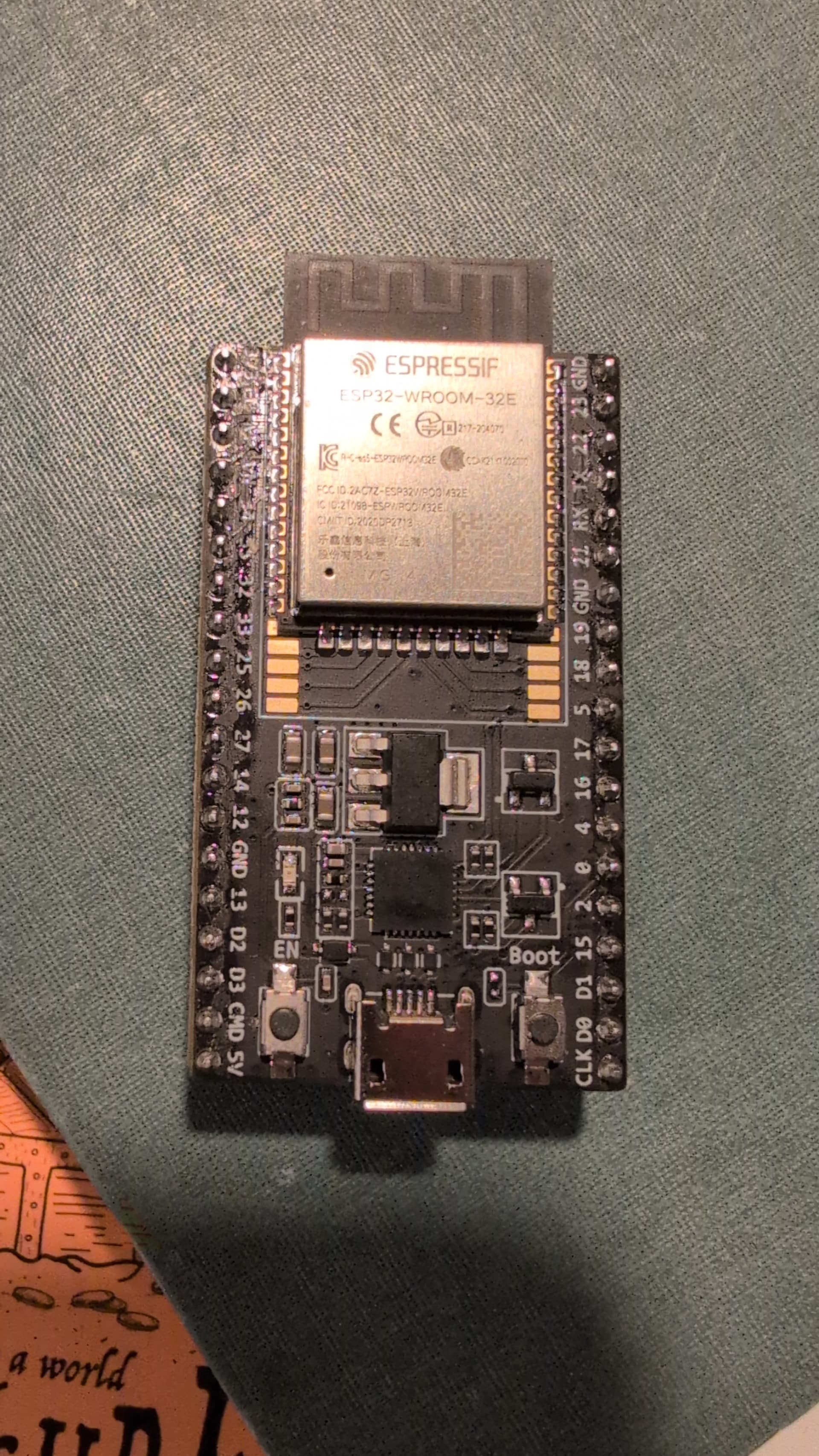
I was getting my LR4 wired up and while I had all of the steppers and limit switches wired up and powered, the board touched the conduit rail in way that made it pop. Now, I don’t see the jackpot access point in my Wi-Fi and I can get the esp out of a boot loop to reflash the firmware. The motors were moving before this happened, so I know the board came to me good.
At this point, it appears my options are to buy a new ESP on Amazon, or just bite the bullet and upgrade to a Jackpot 3. Any recommendations?
I have a new ESP on the way. I’m hopeful that it fixes it. Otherwise, I’ll order a Jackpot 3 and know I’ve learned a lesson about being careful where I set the board when I’m putting things together.
This might sound very lame but can we look into a protective circuit for the ESP via the 3.3v rail to make jackport bullet prove (schottky diode circuitry ) - still a learning curve and this is just my suggestion .
Main point is anywere a consomer can inject wrong polarity and lets concider putting in a protections common points for setting up two of these boards.
Main power
M5 Dail (24V) mis wiring , like pins crossing Vmot 24V and 5v by accident -. Pin short if plug in by accident 24v to 5v dead short from the Power and ground(M5 Dial) or if a consumer has a bad M5 Dail from own install . Higly recommend making that making the Module port ediot proof because putting differential voltage close to each other is not recommended in my world .
Unless all these have already been implemented into the circuitry already
Key words
Lastly - making the ESP Modular replacable just for folks that really disobey all the above rules (jackport 3) rendering it unuseable .Intial sale have to come from V1 Enginering (factory supplied) must
Sorry for my Mumbo Jumbo- Thanks and Happy New Year
Requests for improvement- particularly those with use cases or in particular those with candidate circuit designs- are always welcome.
Do not wire your equipment live. This can’t happen if you aren’t doing that.
Jackpot V1- (or V3 with expansion module)- you can’t do this if you install the module and the standoff while the power is off (Standoff acts as a key)
Jackpot V3- has the proper RJ12 already on the board with appropriate circuitry onboard.
It’s the standard for the Bart Dring board ecosystem which the Jackpot follows. The improvement on Jackpot V3 is to build in the module (with the RJ12) to the board from the outset.
Adds a lot of expense, a failure point, and if you do the things you outlined above the fuse won’t help you.
That board exists- Jackpot V1. For this niche, it will likely keep existing plus for the other use cases (need an external antenna for a metal enclosure, or a test/development mule)
Have any proposed circuit designs? Jackpot V3 got a community review before release, but a good circuit proposal would be evaluated.
Sorry Jim - about my grammer and spelling but just wanted to point out my observation to help improve on the jackpot 3 - was not trying to bash V1 engineering hardwork.
Yes, I have dealt with Ryan myself and he is one of the most honest and genuine people to come across - God bless his heart for all he is doing . I want to see the Jackpot be a true testament of all he is going for this community with NC fluid , some very little changes can help achieve it. Sorry , if I come across as being unappreciative of his hardwork , but want I his jackpot V1 or V3 boards to reach a broad audience with peace of mind .
Replaceable Fuse
Circuit protection
Without a doubt, we will all swap over to jackpot rather than BigtreeTech because no one is supporting their firmware in the hobbyist environment .
Well, I do like the suggestions. Currently, we are in the stages of let’s see how the JP3 fails in the real world. So far it looks like we have had two confirmed manufacturers defect esp32’s (if we get many more I might have hooked something up wrong). The ESP32 circuit is directly from espressif and exactly what I used on the V1 ESP32 so it is pretty proven…still has me worried.
In the JP1, by far the biggest issue was people plugging in the esp32 the wrong way around, and popping them, so we went to built in esp32’s. And wires coving the antenna so I moved the antenna.
I do not think we ever had a reverse polarity accident on the JP1, but we added it to the JP3.
Jim already mentioned the Pendant port issues so we built in and protected ours on the JP3.
Inputs have never seemed to have an issue so they are unchanged.
Outputs are more robust and protected now.
As of right now the only other jp3 issue seems to be either a esp32, or uart chip issue. We just had a board die because it was on and running and got dropped on the metal CNC Rail. I do pay very close attention to the failures.