Yep defiantly going to be using these in my very small storage space.
Thanks for sharing!
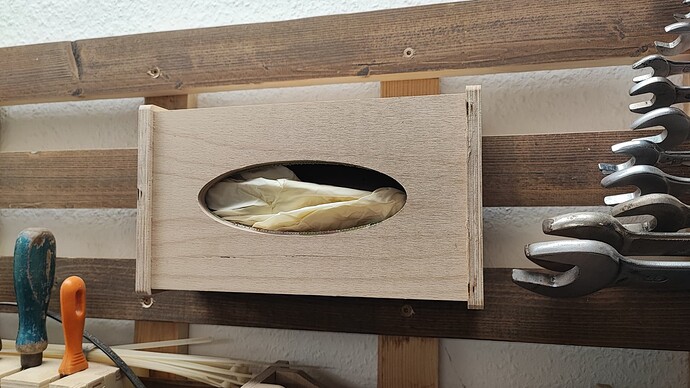
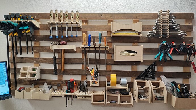
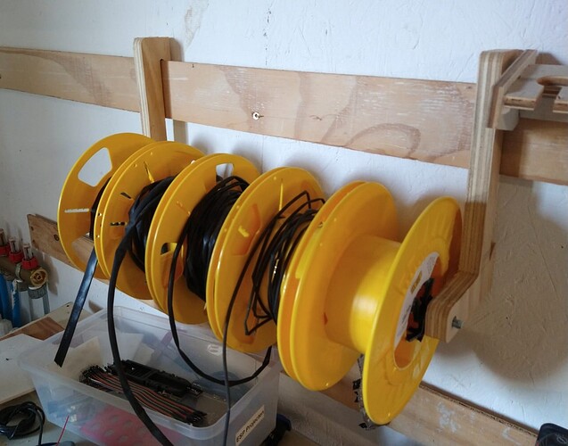
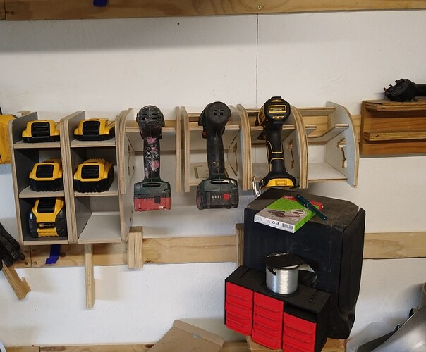
I made some tool and materialholders in the same spirit:
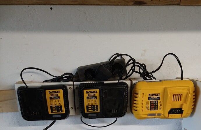
The small drillholders were designed by @Tokoloshe , the large ones were changed by me, the roll holders and batteryholder i designed myself.
I might make a couple of smaller rolls for the heat shrink tube, but it has no priority (so I might do it when I retire)
Uuh, very cool! ![]() Thanks for sharing.
Thanks for sharing.
I think I will help myself to your plans! ![]()
I have a question though: How did you make side holes square? Corner chisel?
I am using dog bones in the CAM. ![]()
I find a flat file makes quick work of them if you don’t want gaps. For shop french cleats, the dogbones are fine, but for boxes or other more decorative items this works well.
Man, I’ve been looking forward to finally doing French cleats in my shop, and you just made it fun, easy, and inspiring! Will definitely upload pics once I finally put them up, thanks a ton for sharing!
Finally getting around to making these things, but I’ve hit a snag: my plywood is 9mm thick instead of your 10mm thick, so I figure I need to adjust the rectangular openings and their respective mates…but it’s proving to be more trouble than I thought it’d be (as always lol). I figure this should be easy to do, but I’ve been stumped for a few hours and figure it’s time to ask for help ![]() What software and what basic steps would you do to accomplish this? (“you” being whomever reads this and feels they can help). For reference, this would be my first real CNC project.
What software and what basic steps would you do to accomplish this? (“you” being whomever reads this and feels they can help). For reference, this would be my first real CNC project.
I first tried scripting out the changes in python so I could batch edit all DXF files. After a couple hours of that I got like 2/3rds of the rectangles edited, but the last 1/3rd proved to be a challenge so I figured “forget it, I’ll just edit them in CAD, can’t be that hard”…
I tried editing the line lengths in F360, which mostly worked but it seemed quite wonky, like 9/10 edits were a simple double click (sometimes a tripe click?) of the line and enter a new dimension (9 mm), but there was at least one line that just refused to let me change it’s dimension…
I tried FreeCAD but as always with FreeCAD, there’s a million nuances that are not intuitive at all, so I’m at a total loss there.
Would appreciate any guidance, as always ![]()
I am using AutoCAD but it’s still really shitty to change those. One would have to parametize everything, then it would be the flick of a button, but it’s really hard to do.
A program that can change the slots on the fly is supposedly lightburn, but I am not sure whether you can later just save it as a dxf again. Maybe Millmage can do it to? It’s free at the moment I guess.
Right on, well hearing it’s shitty even for someone at your level is a bit of a relief at least! I’ll keep looking and will update if I find something.
This is actually fairly easy to do, as long as you start the design process with parameters at the top of your mind.
Trying to parameterize an existing design is pretty challenging.
I was able to edit the lines relatively easily in F360, the steps I took are:
- Open DXF in F360
- Click line segment to adjust (I picked one at a time)
- hit “D” for Dimension
- Click the same segment again (you may need to double click)
- A cell will open and allow you to enter a different number than what is in there
- Type the number you want (9 in my case), hit enter
- You should see it automatically adjust the line parallel to it, so it’s really one operation per rectangle
- Repeat for another rectangle
But now I can’t get the damn file out of F360… file → export keeps giving me files with nothing in them no matter what I try (different output formats, selecting everything/not selecting anything before hitting the button). So yeah, the question now is: How do I get a proper exported file out of F360?
Do you have a free (hobby) license, or a full version?
The free version can only export sketches as DFX. Projects, components and/or bodies only export as STL, STEP or 3mf.
woohoo figured it out, thanks to GPT5 lol. I’m just amazed at how completely unintuitive all of these CAD programs are… must be the reason why there’s 100 of them being actively developed lol. In the GIS world you have ArcGIS ($) and QGIS (free), and after 20+ years of development, they “just work” and anything more you need can easily be handled by python packages like GDAL, but I digress lol.
- you’d think File → Export and picking one of the file type options available would be the move… you’d be wrong! it’s a 2D drawing but the file formats available are all 3D-only, which is why the output is empty. God forbid this globally used, expensive, and invasive software give you a little error message like as a warning! Or just let you pick from formats that would actually work…
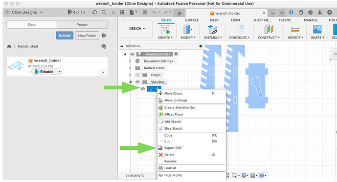
- What you need to do is click on the sketch in the browser, right click, export as DXF. Note that for File → Export, DXF is blocked off as a premium only option

So the winning combo of steps are:
- Open DXF in F360
Click line segmentto adjust (I picked one at a time)hit “D”for DimensionClick the same segment again(you may need to double click)- A cell will open and allow you to enter a different number than what is in there
Type the number you want(9 in my case), hitenter- You should see it automatically adjust the line parallel to it, so it’s really one operation per rectangle
Repeatfor another rectangle and continue, until all adjustments are madeBrowser -> Sketches -> Right click your sketch -> Export DXF(see screenshot below)
That answer from ChatGPT only applies to the free version of Fusion. (See my reply above).
The paid version can export DXF from the file menu.
