OK, quick tutorial time! So you’ve heard the buzz about FreeCAD’s 1.0 release (hooray FOSS!) and you also neglected to order XZ plates with your LR4 parts from @vicious1, what’s a girl to do!? Open up FreeCAD, watch some YouTube tutorials on the subject, and create a 3D part from the 2D DXF files posted in the LR4 files for further processing on Kiri:Moto (here’s a good tutorial from Teaching Tech on YouTube, and also don’t sleep on the V1E documentation!), that’s what! ![]()
FreeCAD 1.0 Guide for Creating 3D STL Files from 2D DXF XZ Plate Files
Preamble and Workbench woes
Having not used “real” CAD software ever (I’ve only used the excellent TinkerCAD and prior to that very novice usage of SketchUp) the workflow for FreeCAD aws pretty foreign. Most of my struggles were rooted in my lack of understanding about the movement between workbenches and the menus/views/UX available in each. I’ll try to note below which workbench we’re in for each step so you can follow along, reply if something isn’t working for you (but probably make sure you’re using FreeCAD 1.0 or something newer).
Creating the XZ-max-DXF 3D STL
1. Import the file
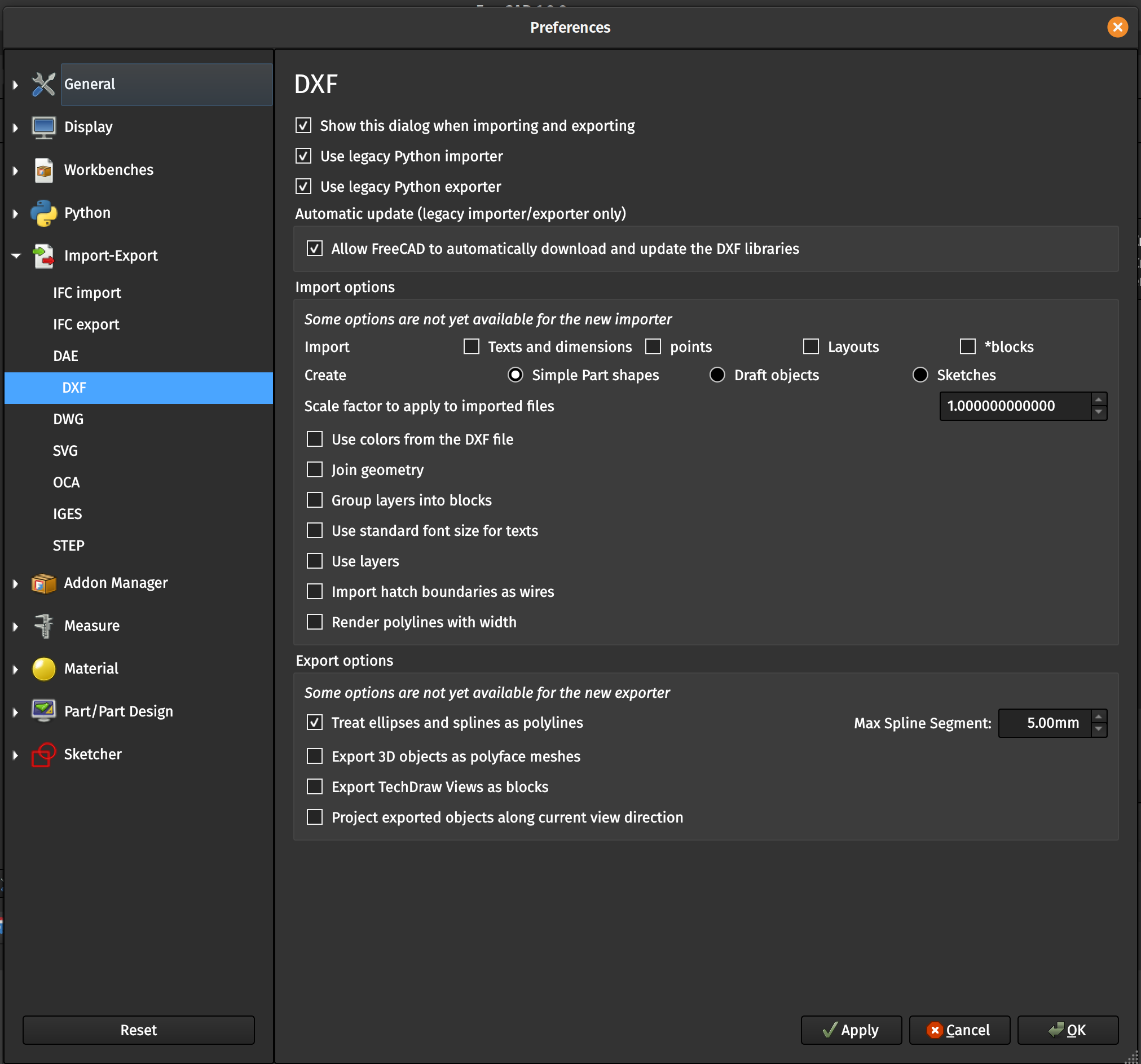
You can open the files directly by double-clicking or via the Open dialogs/buttons or you can go to File > Import, if it’s your first time you’ll be greeted with a listing of options for the DXF import. If you’ve disabled seeing this dialog every time at some point previously you can get back to it via Edit > Preferences > Import/Export > DXF. This is a screenshot of the settings which worked for me in this case but I am not a CAD expert and YMMV for other import operations.

Note in particular, we’re importing/creating “Simple Part shapes”. FreeCAD’s DXF importer isn’t smart enough to create a full, complete Draft or Sketch from this DXF and what worked for me was going through each step from the basic Part shapes. Also note the “Join Geometry” setting. I think for simple drawings this would eliminate the need for a lot of what we’re doing below, but for some reason FreeCAD has a hard time in particular with the outer contour of these plates. But you’ll note below that for the inner V1E-styled pocket FreeCAD is able to import everything properly with no manual manipulate (and also with the circles, but that’s a bit less impressive I suppose).
Once the file is opened or imported you’ll see…a blank screen (or at least I do). Right click in the open space in the main view window and click “Fit all”, this will center the window on your newly-imported part(s).
1.5 Cleaning up the Import
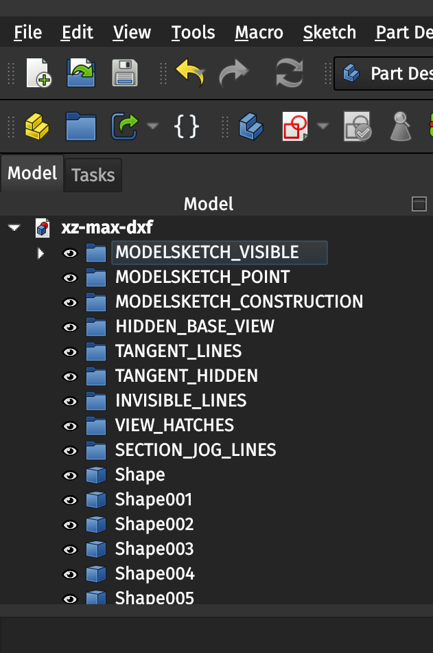
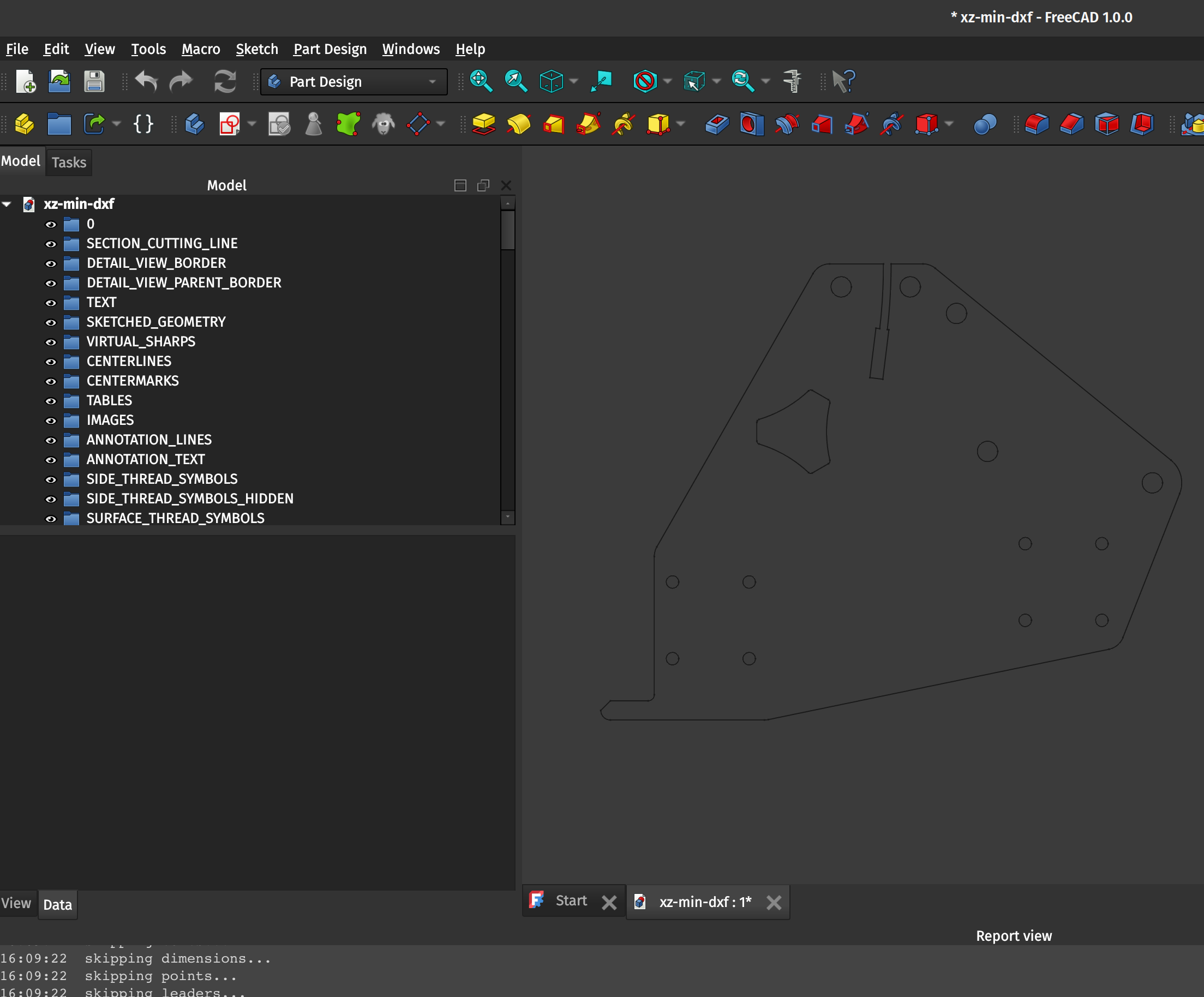
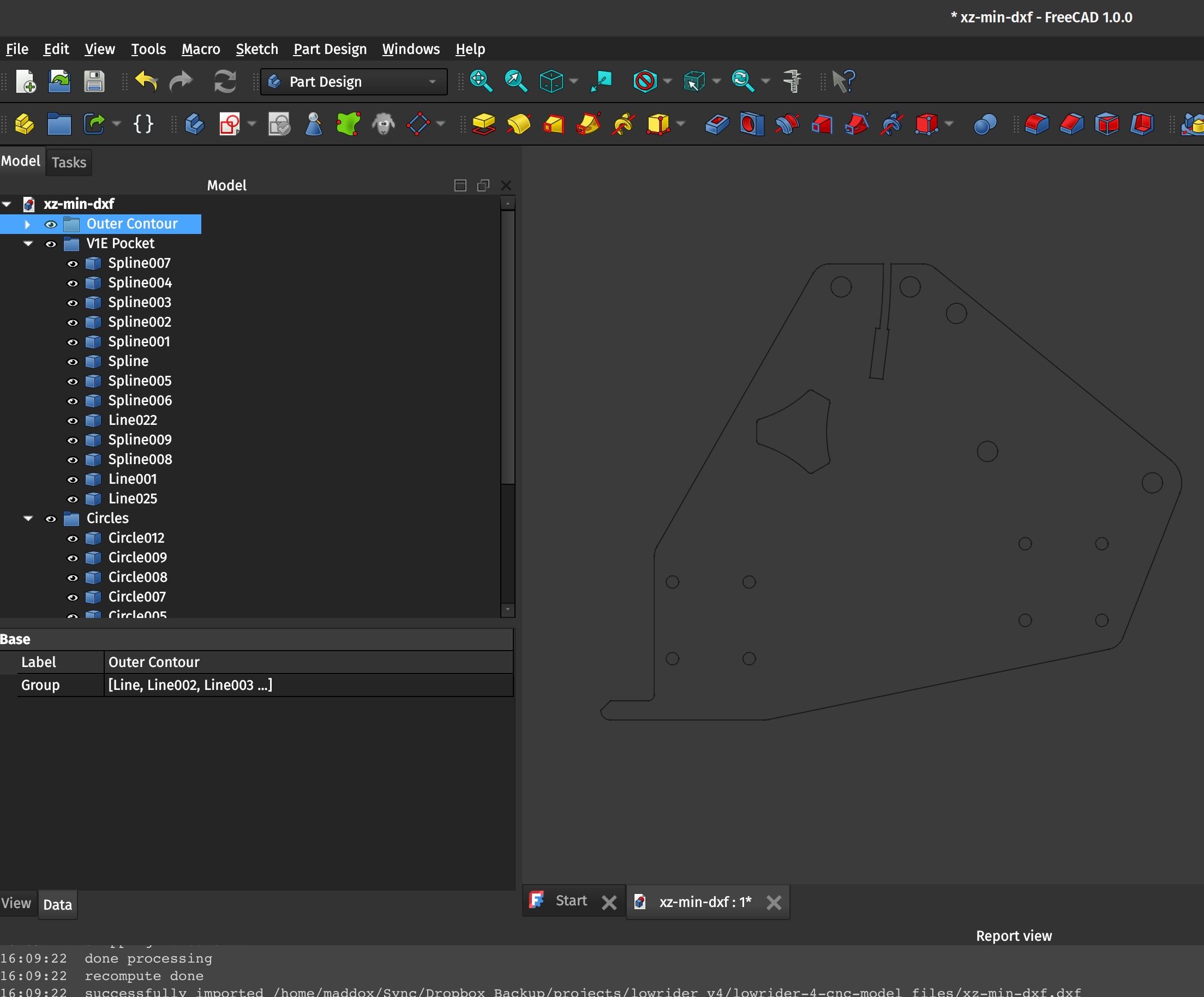
This isn’t strictly necessary but I found that the resulting imported file has a lot of empty clutter in the Model view on the left-hand-side dock, and I cleaned things up by highlighting the empty folders (referred to as Groups, you can tell they’re empty because they cannot be expanded/opened) and deleting them, and moving all of the resulting imported parts into the main document:
Before (midway through cleaning up) and then After:

2. Upgrading the Shapes to Wires
Next, we’ll upgrade the shapes we’ve imported to Wires, which can then be converted as I understand things to Sketches. Some of the shapes upgrade to…boxes? And some to shapes. I’m not sure the difference, and it doesn’t appear to matter.
2.1 Draft workbench
Switch to the Draft workbench using the drop-down menu at the top of the FreeCAD window, you’ll be greeted with the following view:

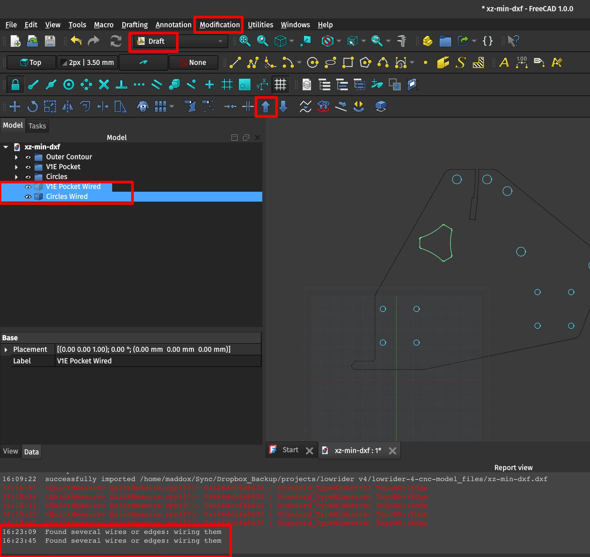
2.2 Upgrading the V1E-style pocket to a wired…wire
Now, you can use the Edit > Box Selection (shortcut is Shift+B, you will use it all the time I think) tool to fully select the items of the V1E-styled pocket. You could also select everything manually using Shift+Ctrl+Lclick or in the menu (as you mouse over things are highlighted in the main view window) but Box Selection is so much easier. I found out about this tool halfway through my struggles with FreeCAD yesterday along with it’s corresponding Box Zoom (View > Zoom > Box zoom or Ctrl+B) and it makes things SO much easier. Once selected, it will all be highlighted like this and you can use the Modification > Upgrade (shortcut U,P or the ![]() icon on the Draft toolbar) to upgrade the Shape to a Wire. Note the message about joining/closing the Wires:
icon on the Draft toolbar) to upgrade the Shape to a Wire. Note the message about joining/closing the Wires:

2.3 Upgrading the circle shapes to wires
Then you can do the same thing with all of the circles, all at once (I’m not sure these steps need to be separated but it seemed easier to me). I simply select each “Circle” item on the left hand side menu at once (Ctrl+Shift+LClick) and then use the U,P shortcut as above. Note: this hides from vie the individual Circle parts but does not delete/remove them (unlike the pocket above) and creates a “Block” which tripped me up for a bit. I thought it wasn’t “wiring” them, but I noticed that the success message was the same, i.e. “Found several wires or edges: wiring them” so I proceeded with the rest and it all seems to work fine.

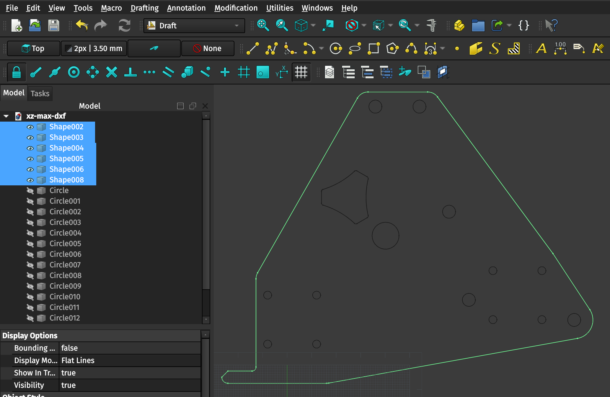
2.4 Upgrading the plate contour to a wired shape
Select the remaining unchanged Shapes which make up the contour of the XZ plate and upgrade them like you did the previous shapes. This will look like a total success (creating a new Block similar to how it did with the circles), but the wiring has some problems which we’ll fix in the next section.
Before:
After:
3. Upgrading the Wires or Blocks to Sketches
Draft Workbench (still)
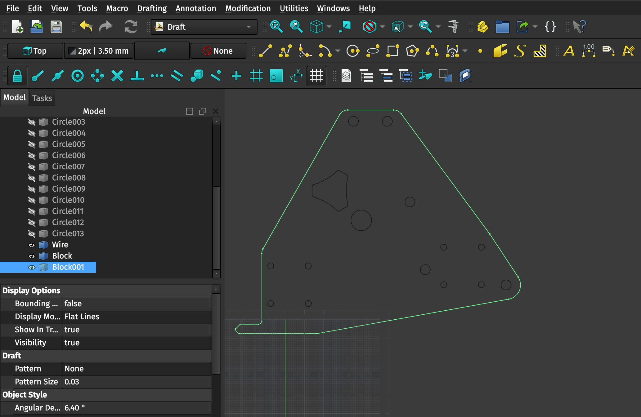
For each of our resulting Wires (in the case of the V1E pocket) or Blocks (in the case of the Circles and the contour), we can now use the Draft workbench to convert them to Sketches. Sketches are the object type in FreeCAD which can be made three-dimensional (again, as I understand it). For the pocket (“Wire”), circles (“Block”), and contour (“Block001”) you can select each individually and then use Modification > Draft to sketch to create a Sketch from each Wire or Block individually. There’s a toolbar icon for this which is difficult to describe but I’ve highlighted in in this image:
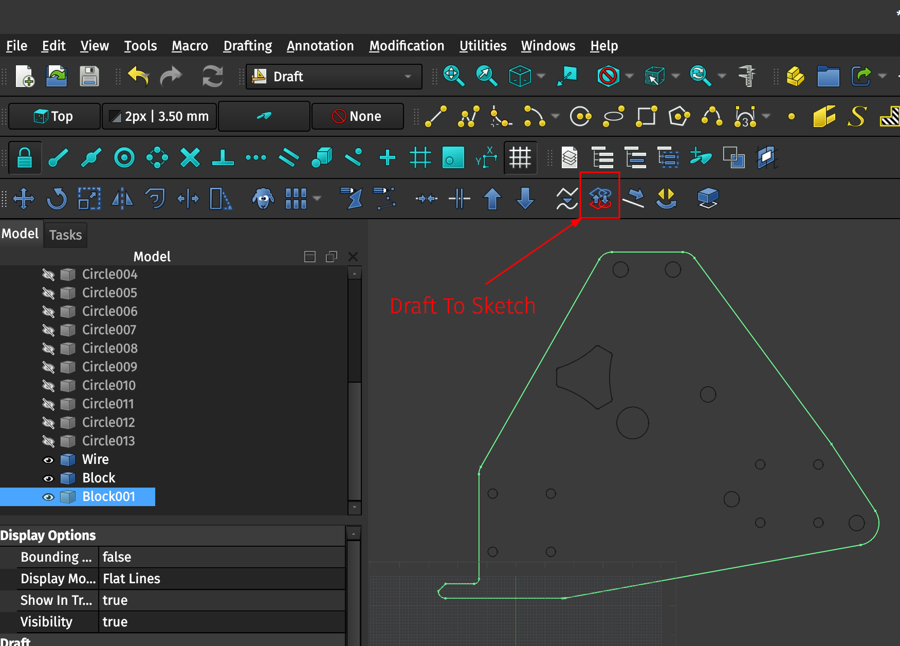
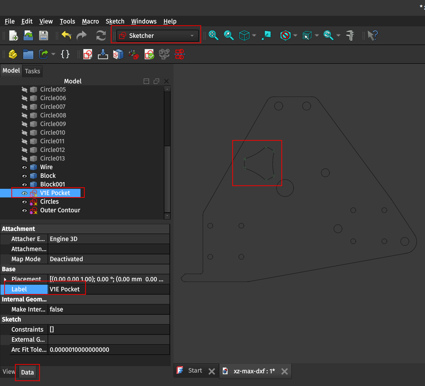
The result will be three independent Sketch objects (which you can Rename using RClick > Rename or F2 or in the Data tab, Label element) to keep better track of which is which. You can then switch to the Sketcher workbench for the next step. Here’s a screenshot highlighting most of those points.
4. Using the Sketcher workbench to validate and finish the objects
For each of the resulting Sketches you can use the Sketch > Validate sketch function (which also has a toolbar icon which I’ve highlighted in the screenshots) to check for any problems with the Sketch after doing all of the prior steps.
4.1 Validating the V1E Pocket
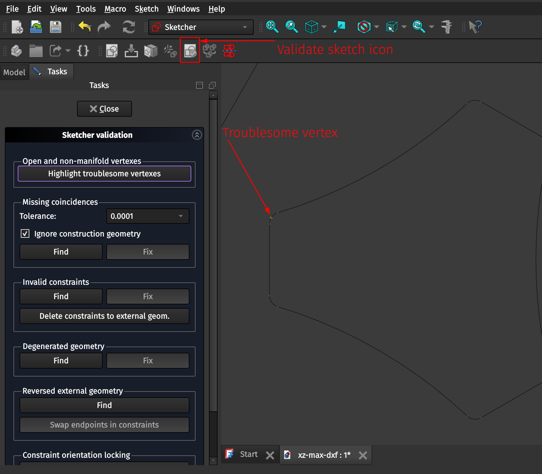
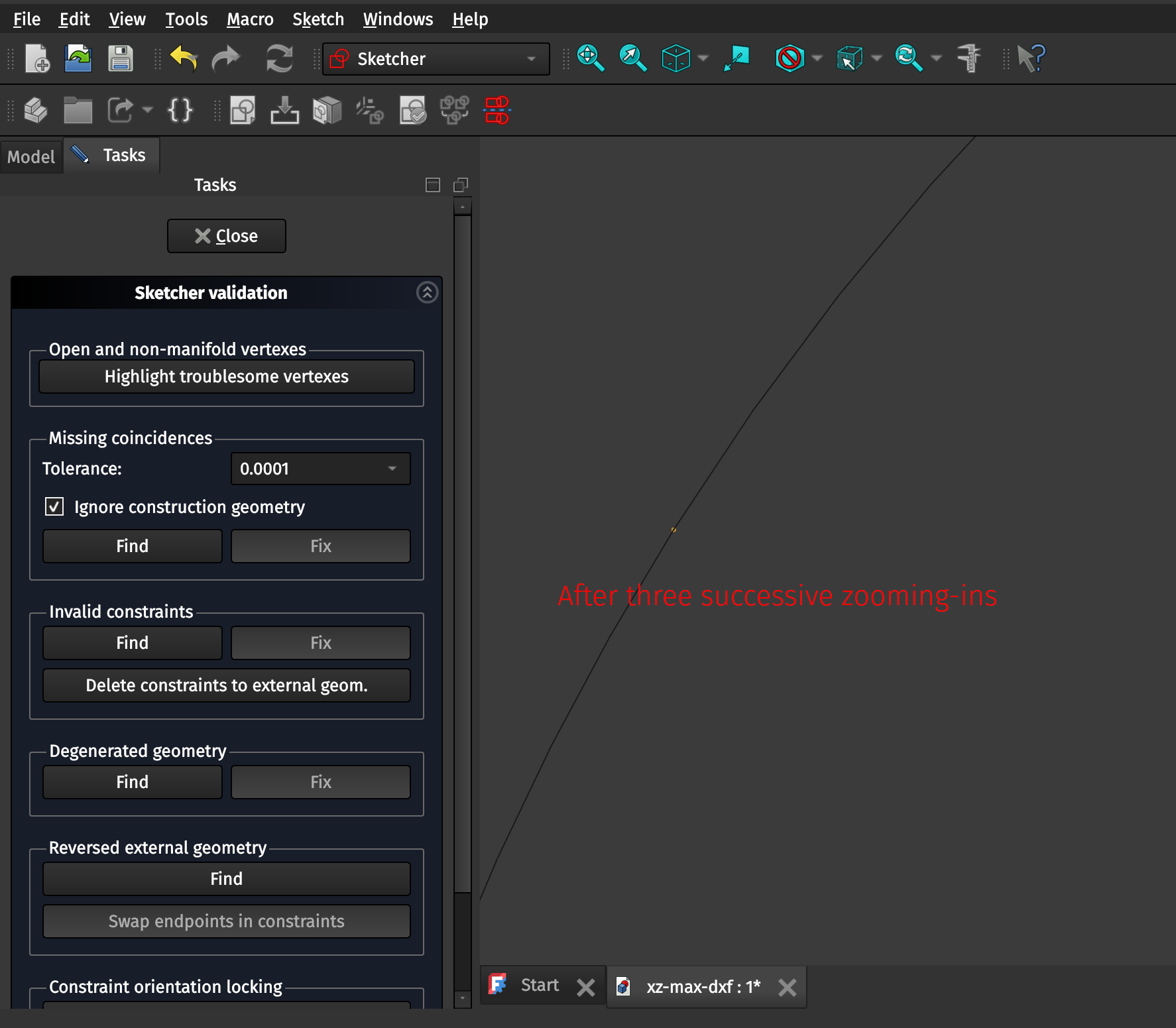
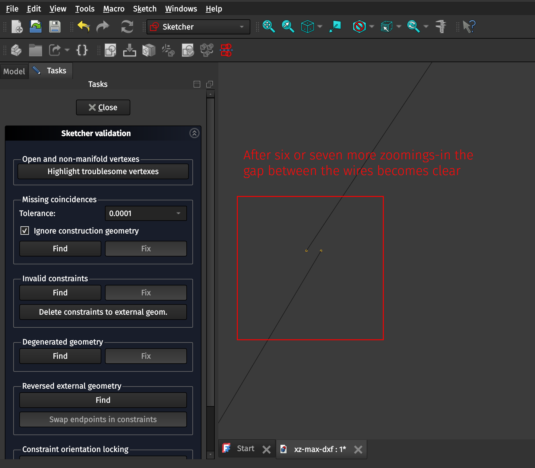
Select the V1E Pocket sketch in the Sketcher workbench and click on the Validate Sketch toolbar icon. This will bring up a menu depicted in the following screenshot under the Tasks pane. You can then check the wiring/completeness of the Sketch using the “Highlight troublesome vertexes” tool. The tiny orange dot in the result indicates that the Sketch is not fully-closed or has an open wire/vertex. We can validate this by zooming WAAYYYY in using the Ctrl+B/Box zoom tool, as in the following screenshots.
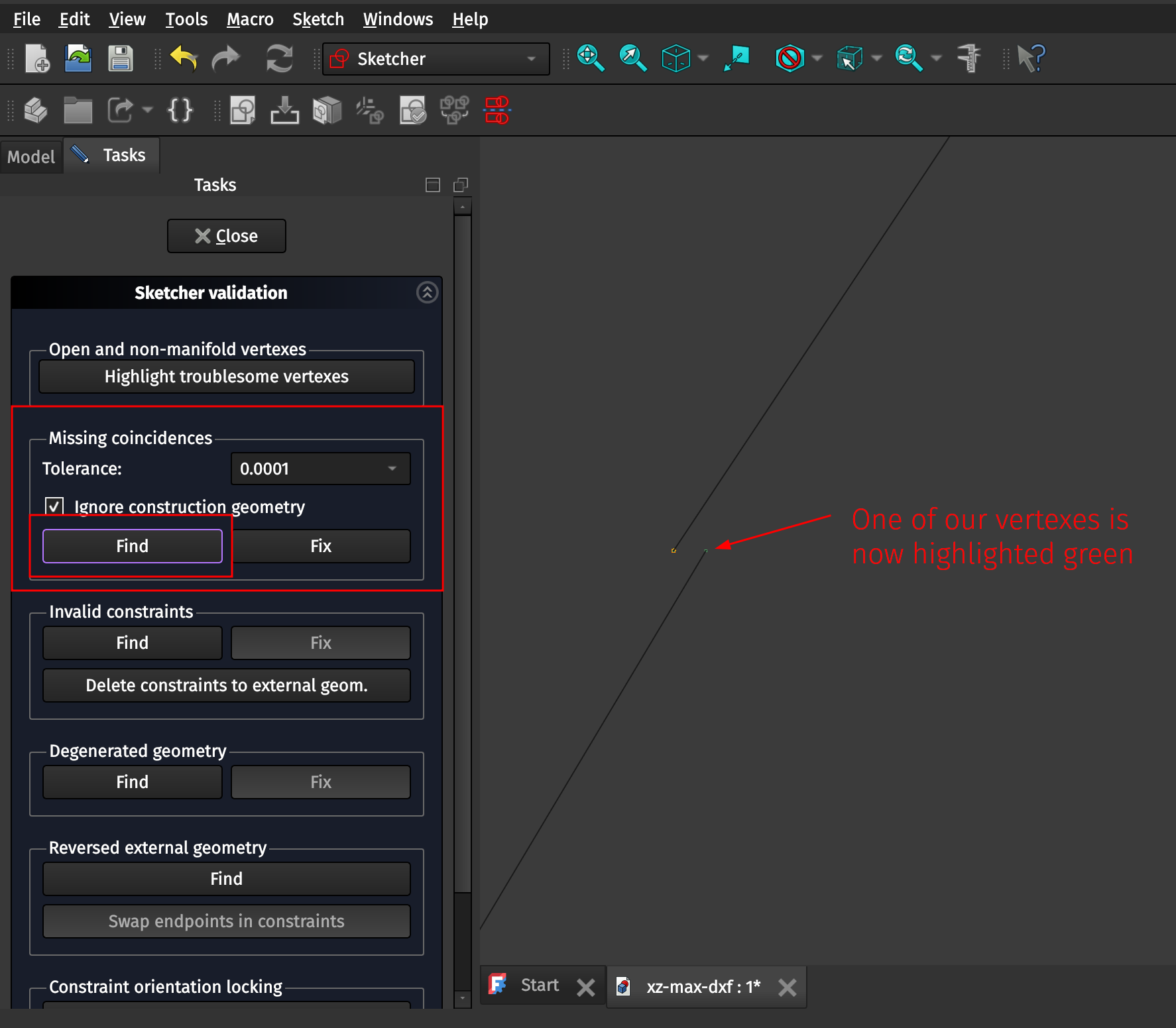
In the case of the V1E Pocket object, you can use the “Missing coincidences” tool to automatically fix this gap in the wires. It will indicate in the log that it has successfully repaired the Sketch. First, hit “Find” under the Missing coincidences menu and it will highlight one of the two vertexes you’ve zoomed in on in green. The “Fix” button will then be activated. Once you click Fix, it will repair the Sketch to close the loop.
Using the Find button:
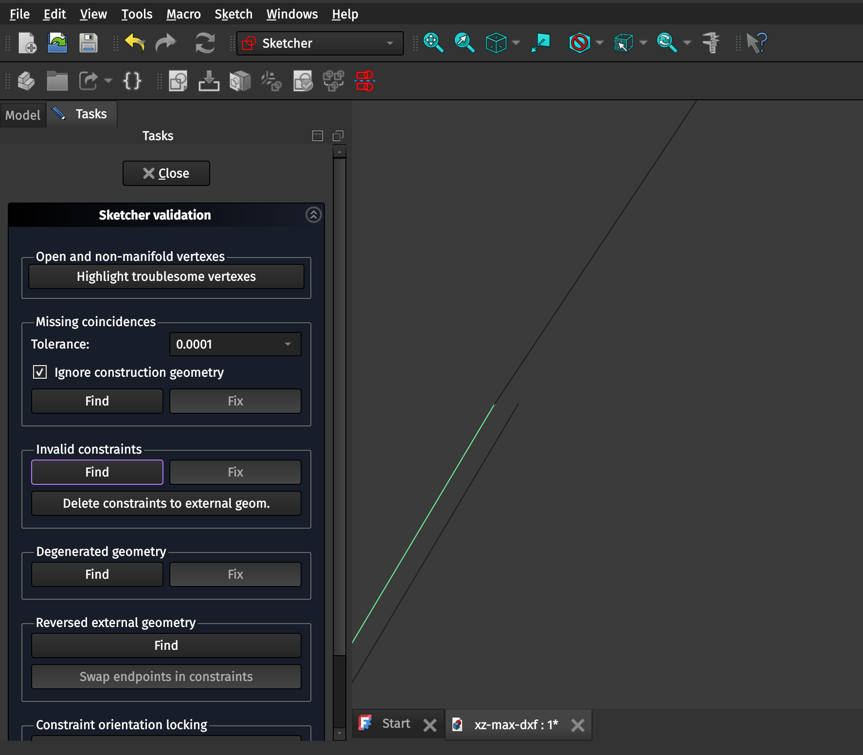
After clicking the Fix button (no, I do not know why there are two lines now and it doesn’t seem to matter):
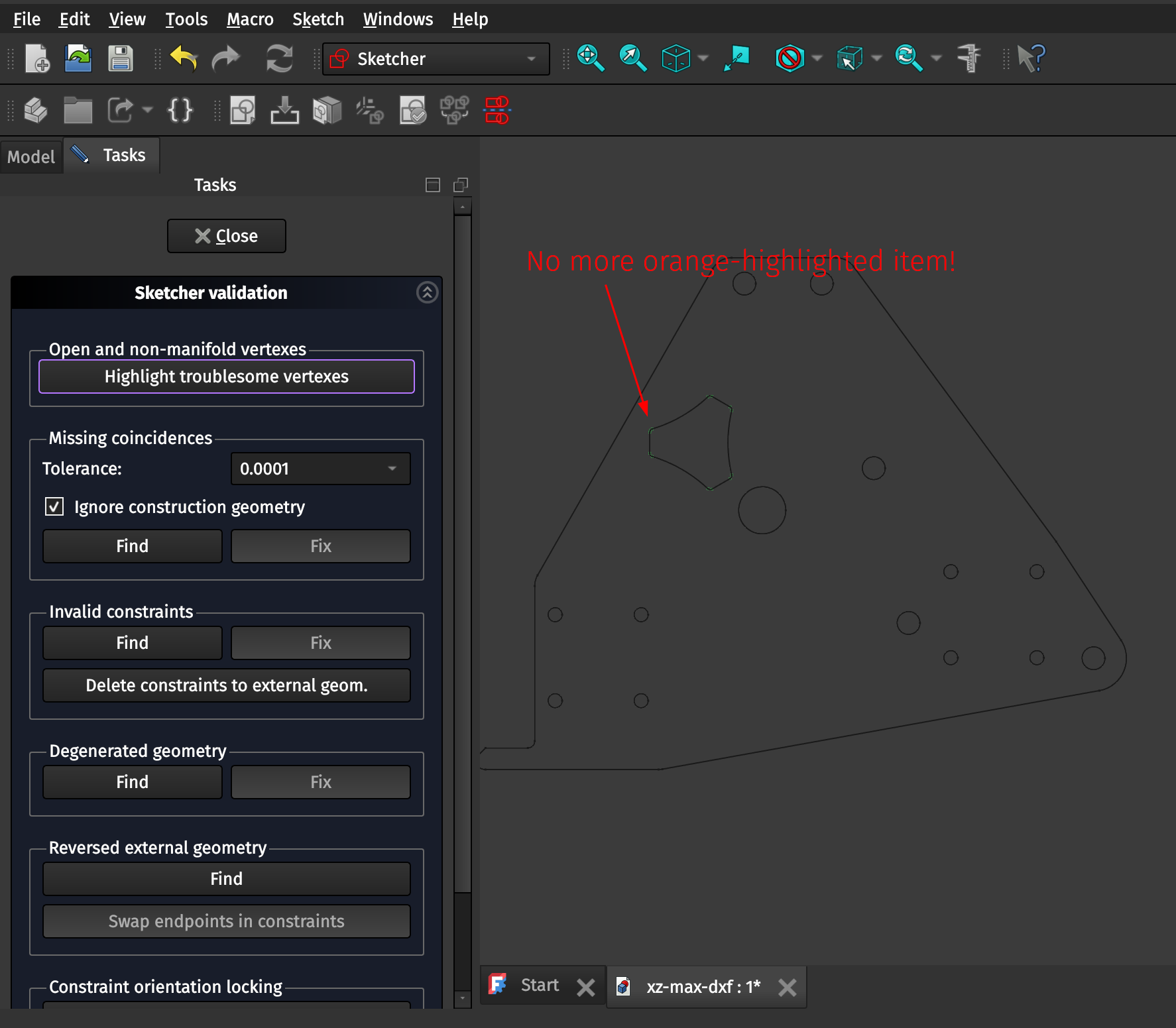
After zooming back out using the RClick > Fit all function, you’ll find that you can no longer highlight the troublesome vertex. The Sketch is now fixed! You can click Close in the Tasks menu to exit the Validate Sketch tool for this V1E Pocket sketch.
4.2 Validating the Circles
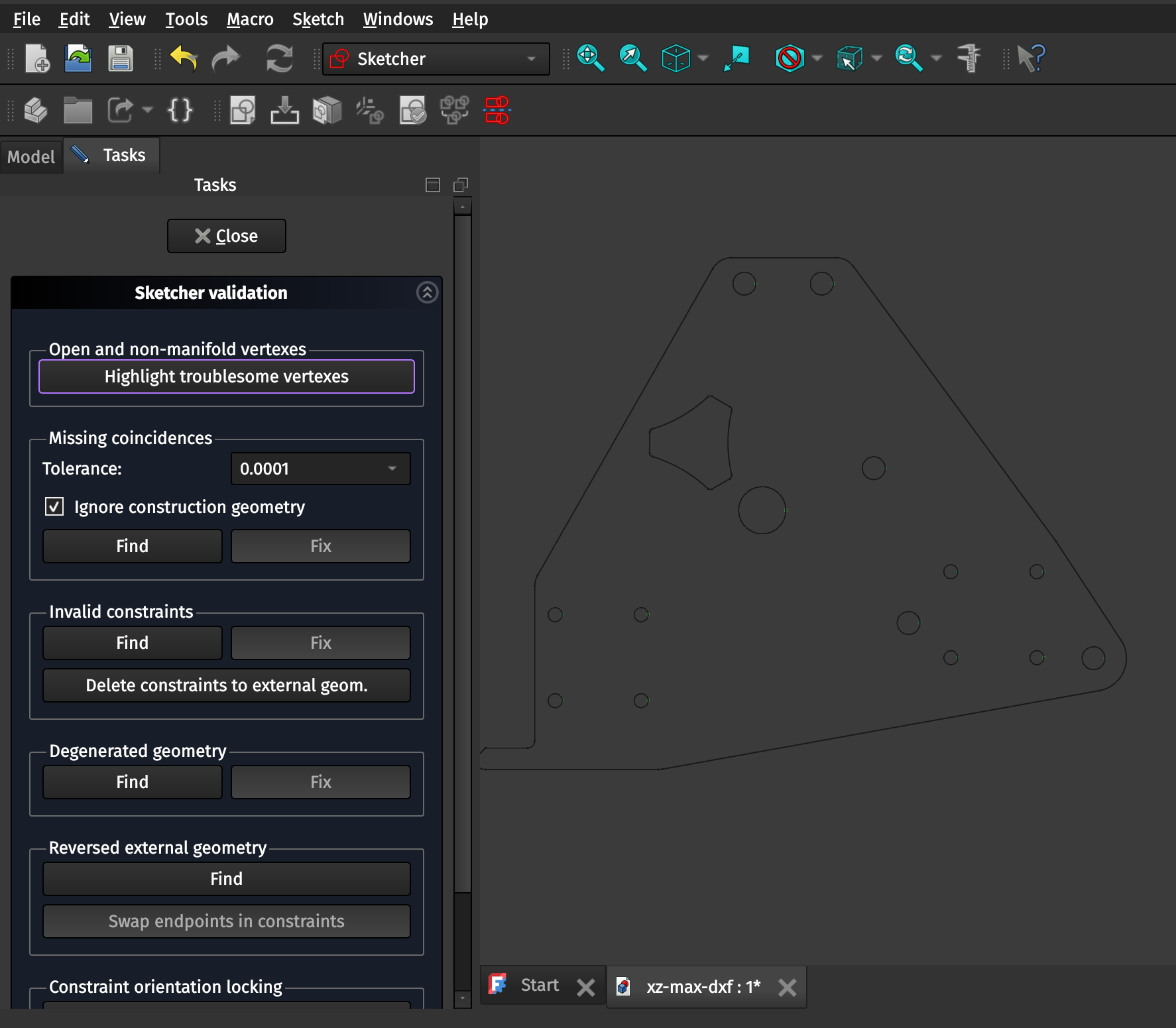
If you follow the same steps for the Circles sketch you’ll note that under the Tasks pane both the Highlight troublesome vertexes tool and the Find button in the Missing coincidences tool come up with no results (all green vertex points are displayed, no orange), indicating that the Circles are validated properly with no further changes.
4.3 Validating the Outer Contour
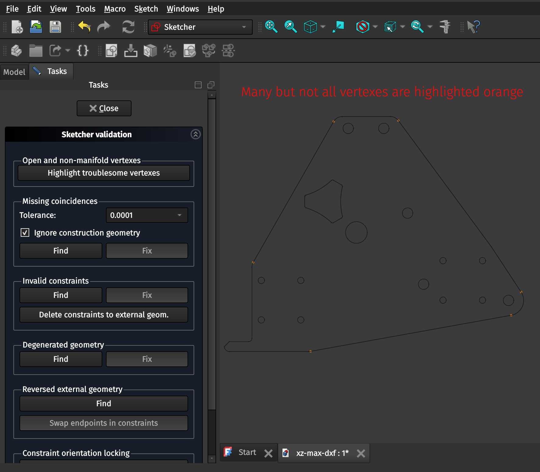
If you follow the same steps as for the prior sketches, you’ll note that the Outer Contour has many vertexes which indicate they are “troublesome”.
Unlike with the V1E Pocket sketch, the Missing coincidences tool is unable to automatically fix all of the highlighted vertexes, which means we need to manually fix them using the Sketcher workbench.
NOTE ON THE ABOVE PARAGRAPH: In some cases when I’ve done this the Missing coincidences tool WAS able to fix things, and in other cases it was NOT able to fix things. I was confused by this for a while, but this appears to be due to having the Tolerance in the Missing coincidences tool set to too small of a precision (in the case of this model, below 1E-06). I didn’t realize this when I first began writing this document, and therefore I am documenting below how to manually fix missing coincidences. Follow the steps for Validating the V1E Pocket above to auto-fix, and keep your tolerances above 1E-07 and it will automatically fix them just fine!
Since we cannot (see above NOTE for exceptions to this statement!) use the Missing Coincidences tool to automatically fix the missing coincidences we are instead going to fix them manually. Close the Tasks pane and double-click on the Outer Contour Sketch in the Model pane to open the Tasks dialog for the Sketch.
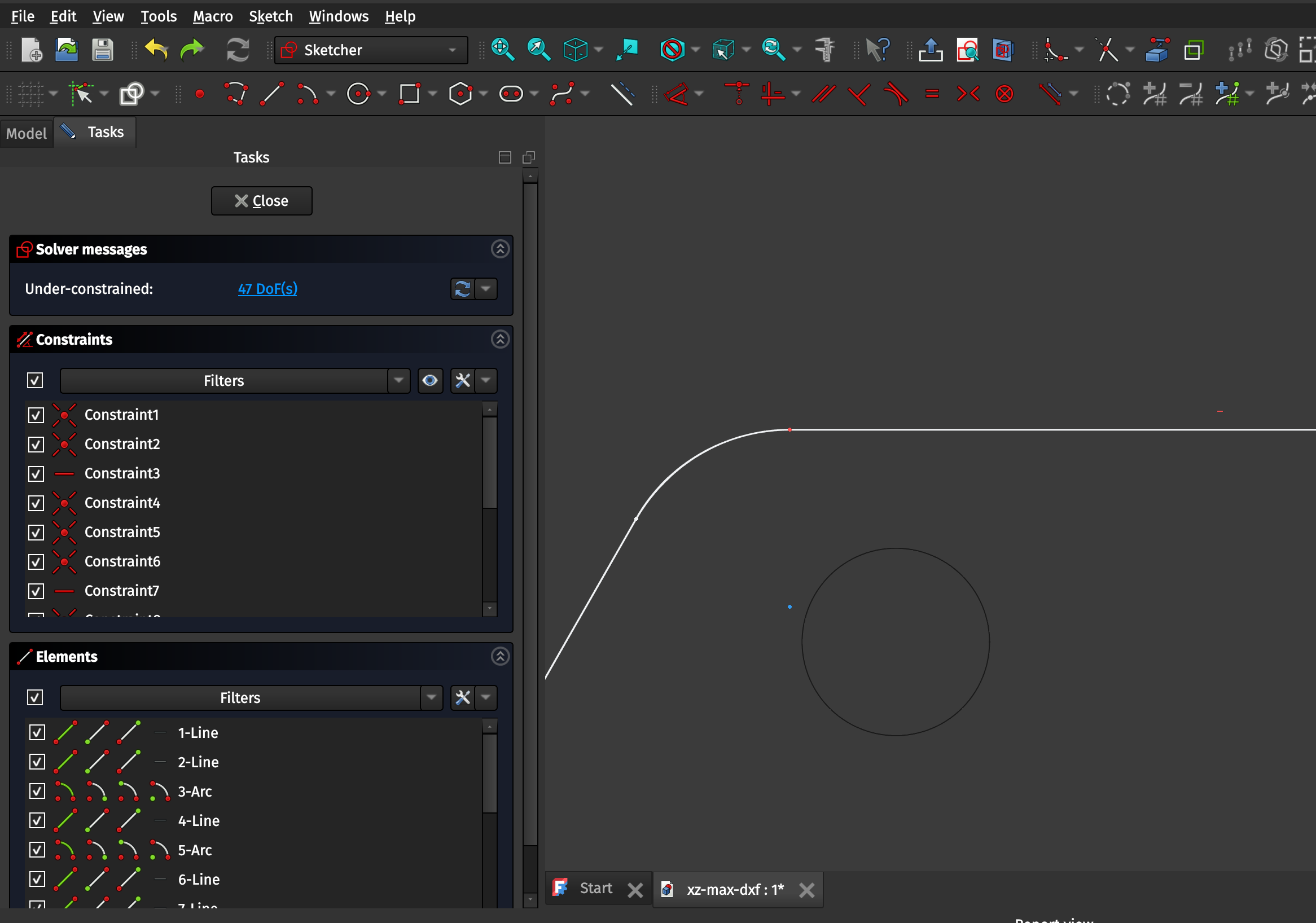
You’ll now see a listing of Constraints and Elements which make up the Sketch on the left hand side of your screen. You’ll note that the troublesome vertexes originally depicted in orange in the Sketcher Validation tool are now un-highlighted white dots, whereas the non-troublesome/valid vertexes are depicted as orange dots along white line segments.

If we zoom in a few times the difference is easier to see:
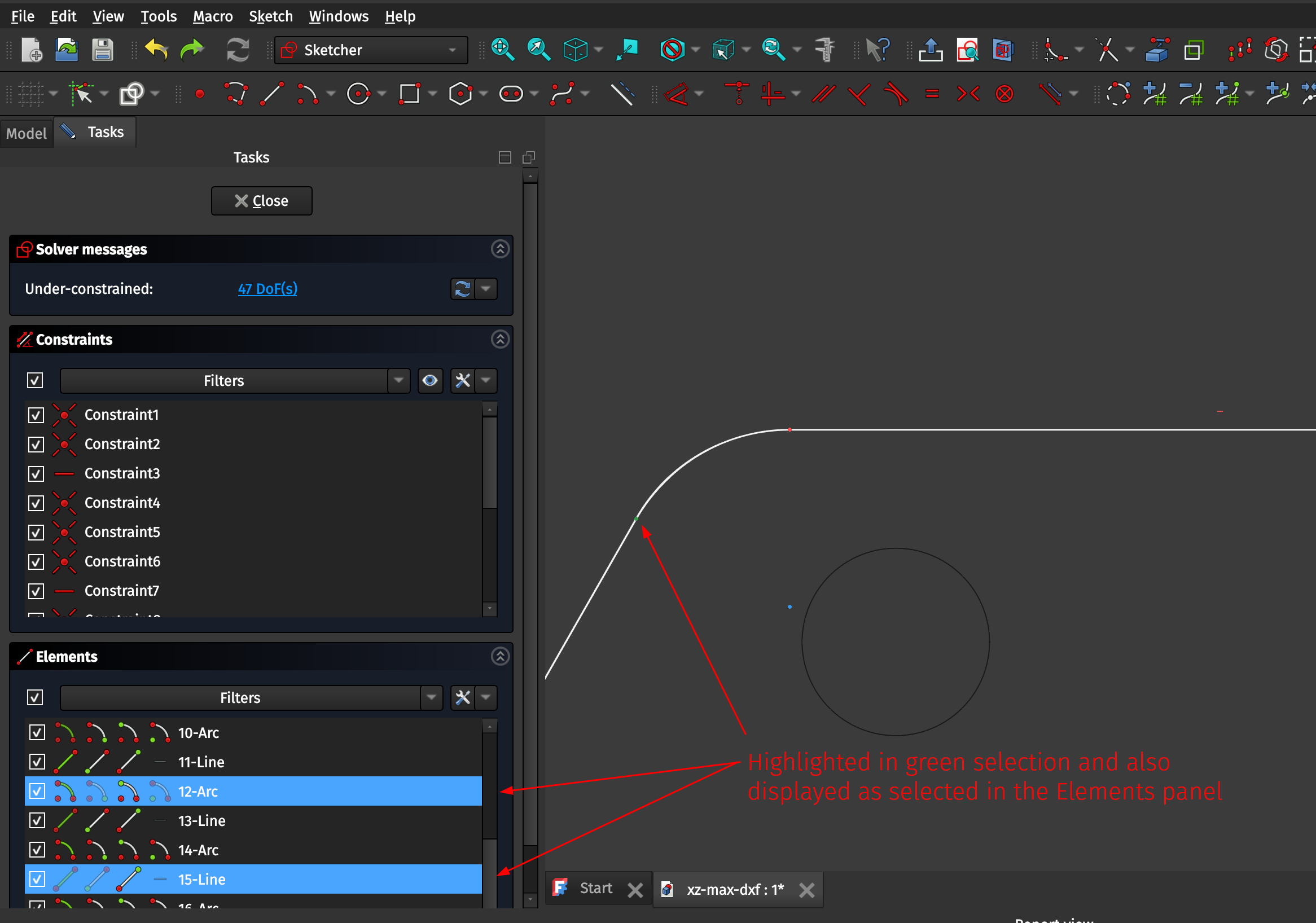
To fix these non-coincident vertexes manually you can drag and highlight them within the Sketcher workbench while clicked into the shape (i.e. with the Tasks pane open on the left and the Constraints and Elements menus showing) which will then highlight the selected points in green and also will show the points as selected in the Elements panel, and then you can use the Sketcher > Sketcher constraints > Constrain coincident tool which will update the color of the selected vertexes indicating they are now coincident (touching or joined). Do this for all of the troublesome vertexes indicated in prior checks, and then use the Sketcher > Validate sketch tool to ensure you fixed them all (the tool will simply not highlight any vertexes if you finished fixing them all).

4.4 Merging the Sketches
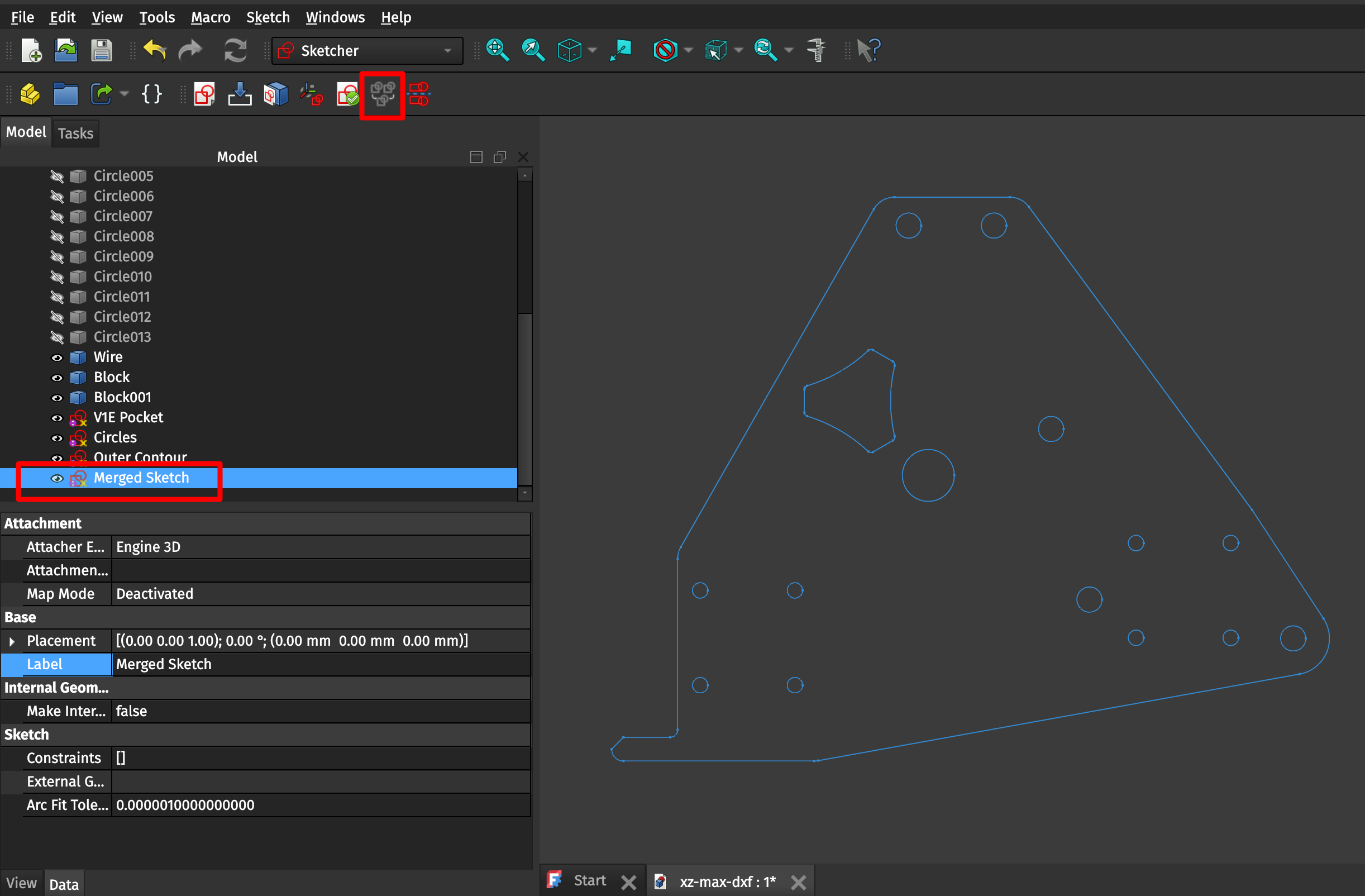
Finally for the Sketcher workbench we will merge our three Sketches into one to then manipulate in the Parts or Part Design workbenches. The Sketch > Merge sketches tool will create a new sketch which contains all of the three previously-individual sketches, which we’ll then rename as before to something indicating which sketch it is.
5. Using the Part workbench to create a solid
5.1 Using the Extrude tool to create a solid 3D part
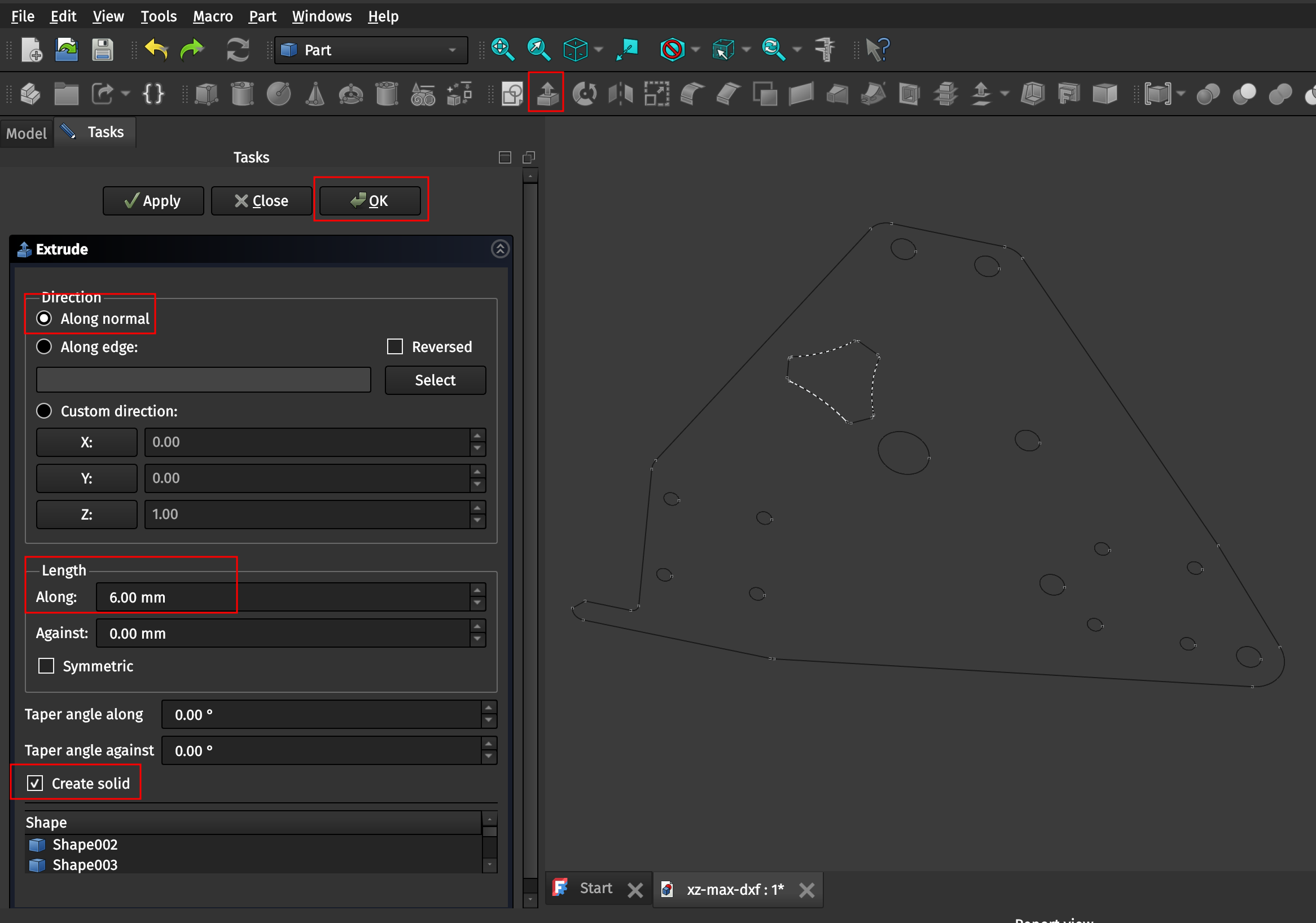
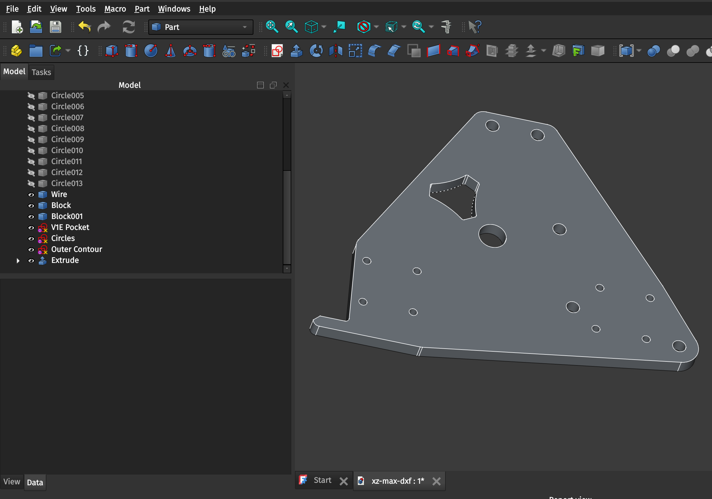
The final step (yay!) is pretty simple. Now that we have a properly-closed sketch we can use the Part workbench’s tools to create a solid shape out of the 2D sketch. Open the Part workbench, select the joined sketch from the prior step, use the Part > Extrude tool which will open a new Tasks pane. In that pane make sure you are extruding Along normal (presumably in a perpendicular direction from the two dimensions described by the sketch). Your Length is Along that perpendicular direction and represents the thickness of the resulting Part, in my case I picked 6mm because my aluminum plate I’m using is 6mm thick (which is about 1/4 inch). Lastly select the Create solid option which will close off the faces of the part. Click OK to create your 3D part!
5.2 Exporting the new Extrusion to STL
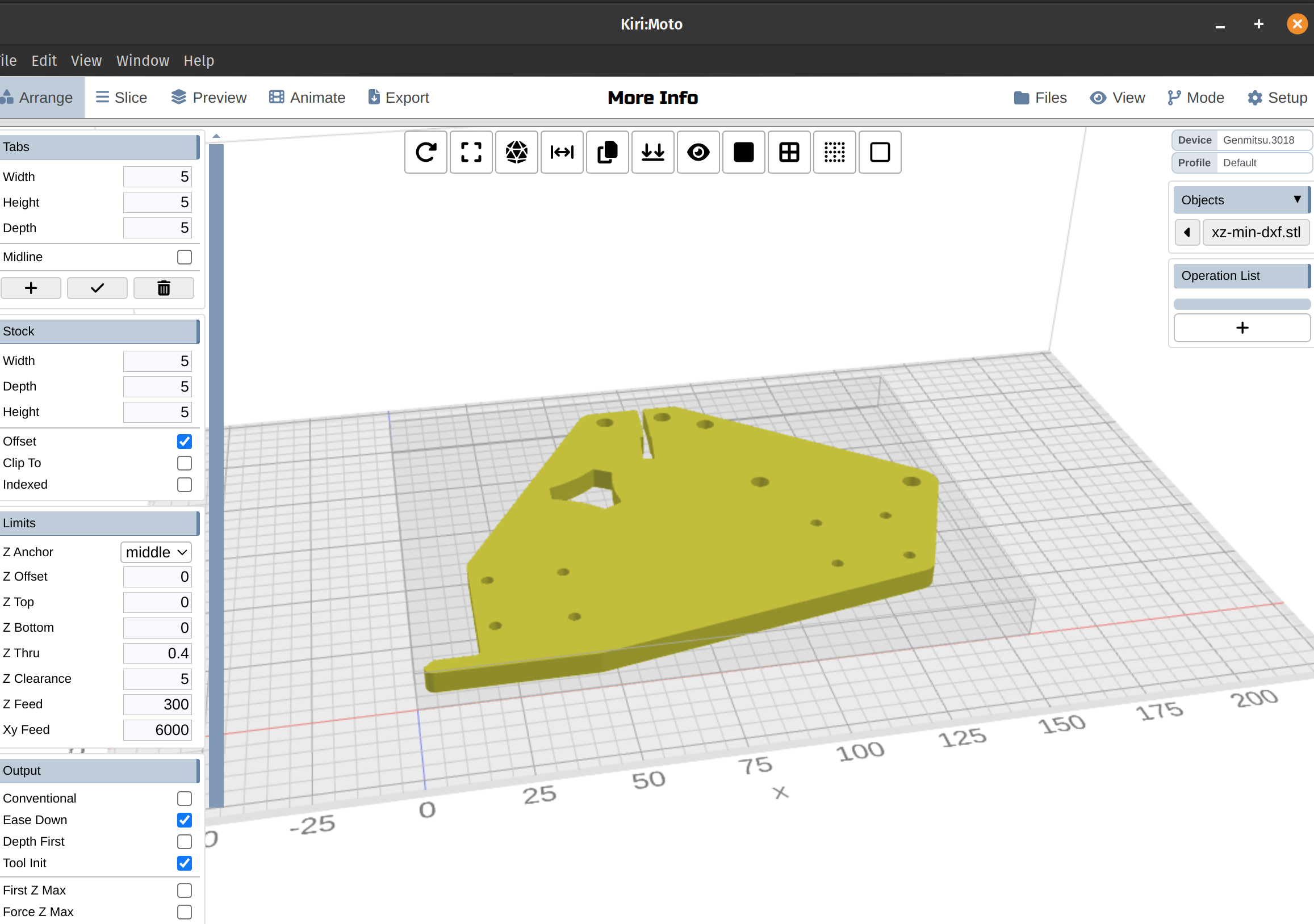
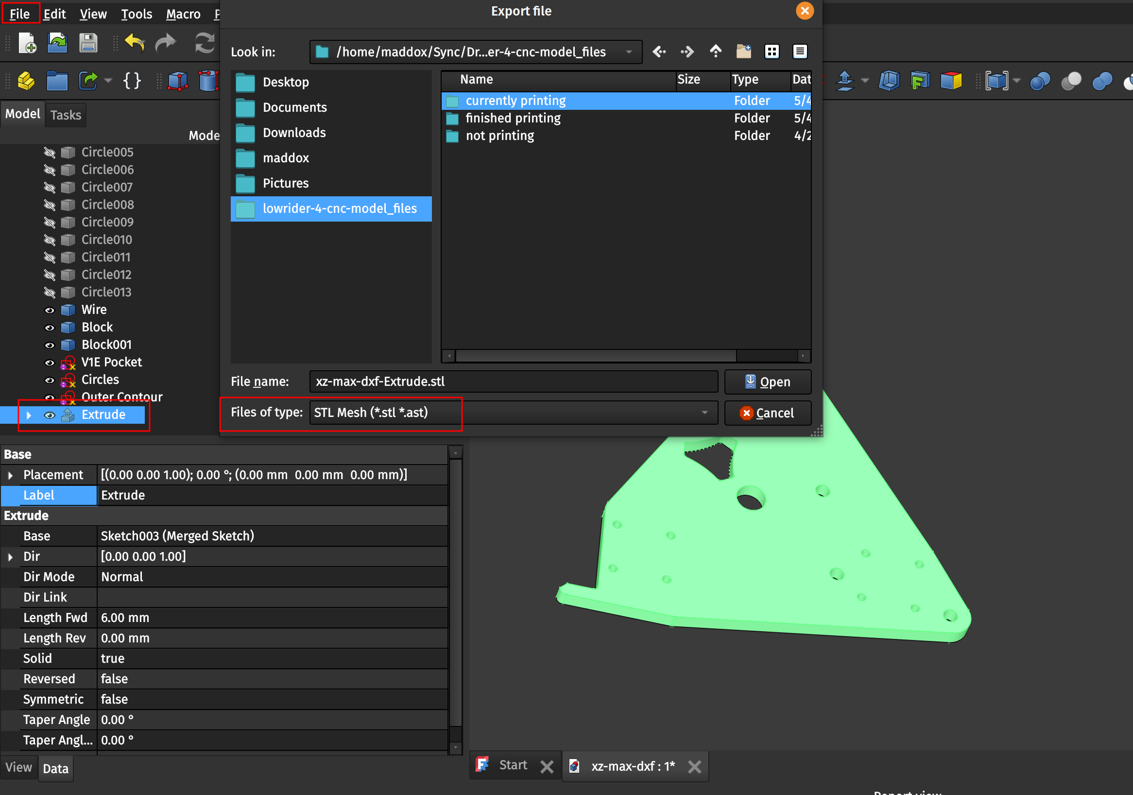
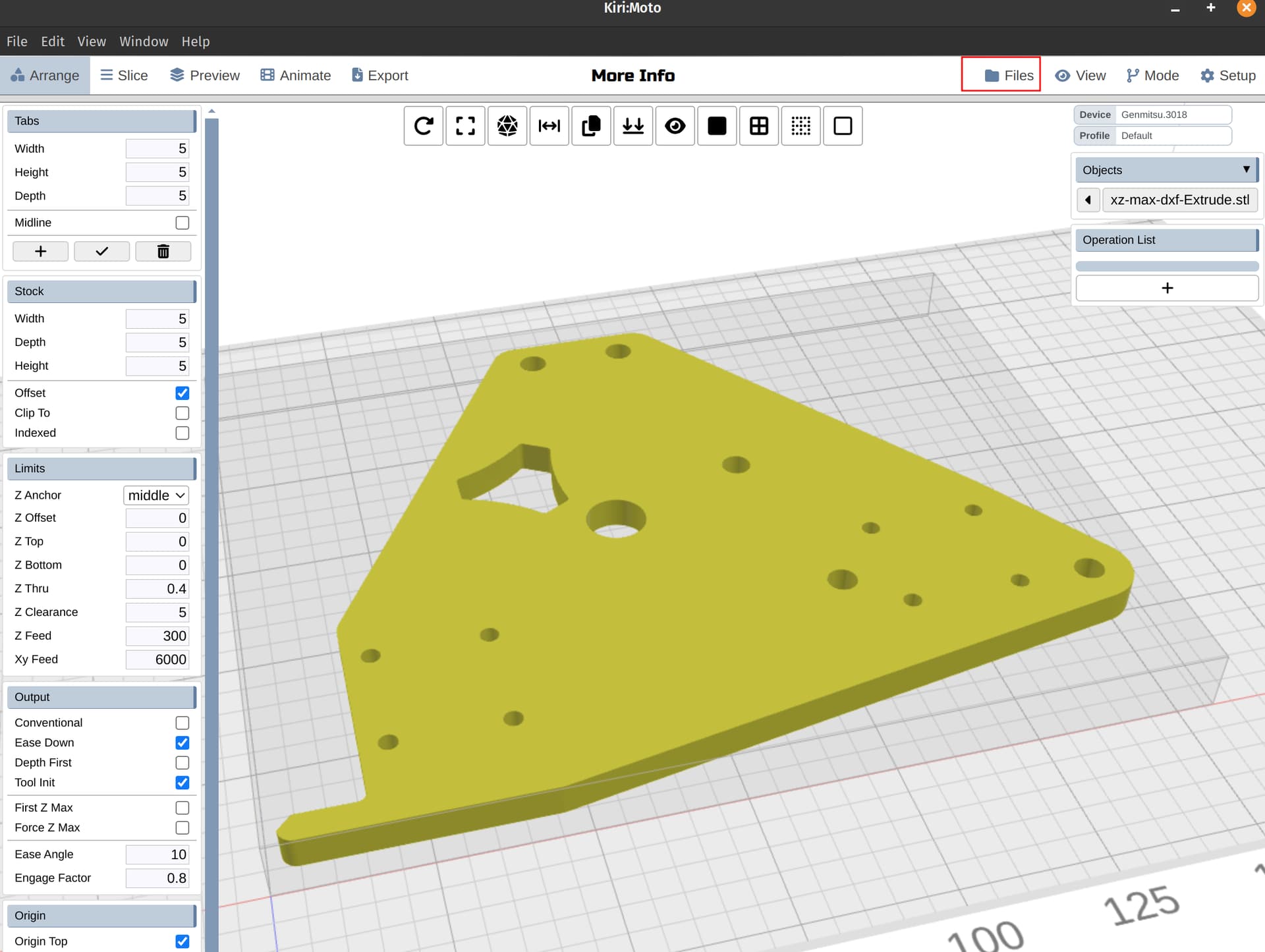
This part is very simple. Open File > Export or use the Ctrl+E shortcut to open the Export dialog. Select the file type you want to export as, and name the file appropriately. You can then Import this file into Kiri:Moto (or any other STL-capable tool) to validate it worked properly. In Kiri:Moto this is done using the Files > Import menu, a screenshot is displayed below as an example. You’re all done!
Creating the XZ-min-DXF 3D STL
1. Import the DXF file
The Import stage is basically identical to last time, but for reasons you’ll see later I actually let the Import do even less work than last time, and unchecked most of the options to join or manipulate the shapes prematurely since I wanted the imported shapes to be as simple as possible because I have to do some cleanup on the contour this time.
2. Separate out the shapes for Outer Contour, Circles, and V1E Pocket into groups
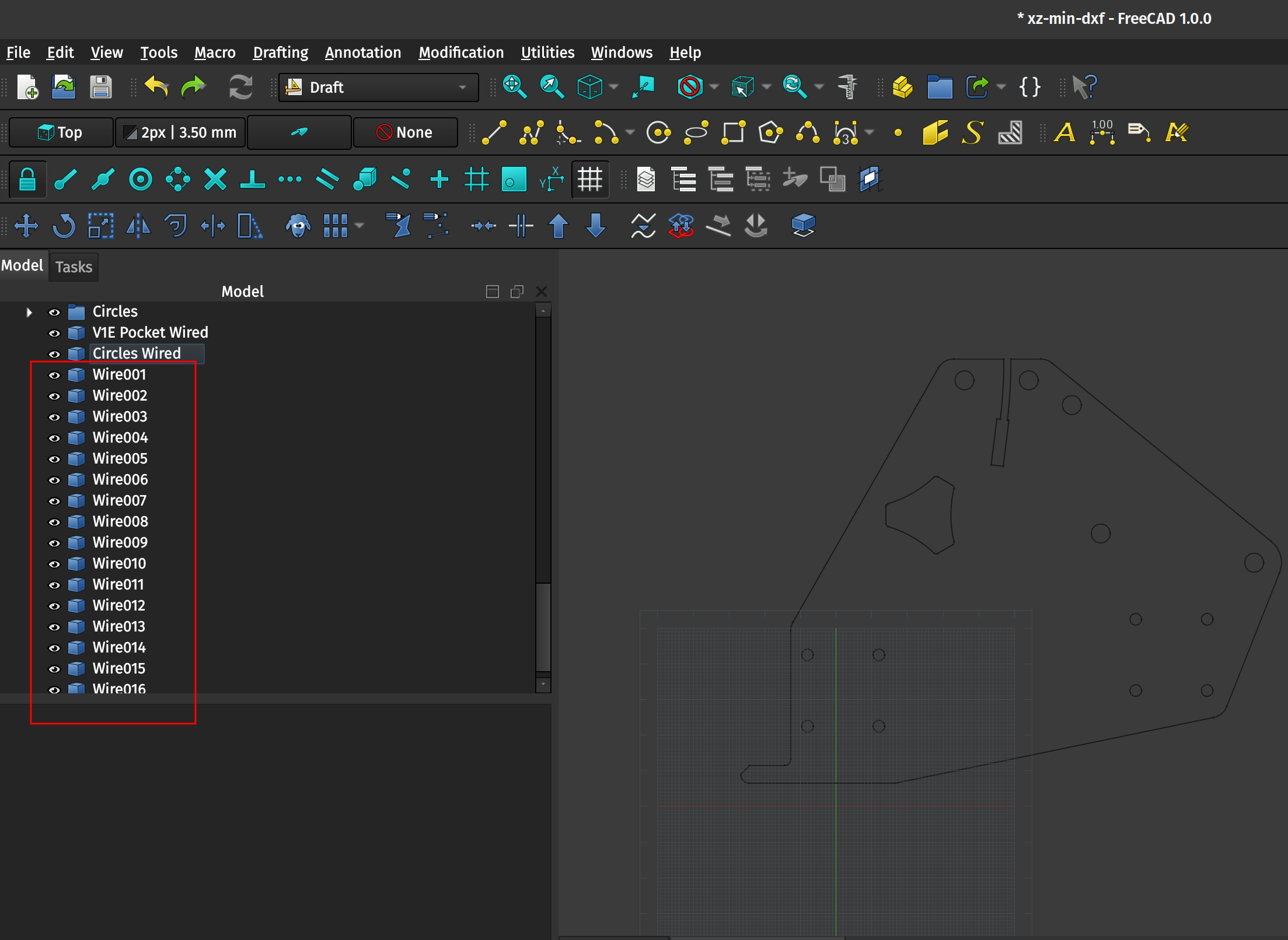
Just like for the prior XZ-max plate we’re going to open the Draft workbench and do a bunch of cleanup on the Model’s file structure to organize things and make everything easier to work with. Here’s a before and after showing the cleanup I did, you do you boo.
2.1 Upgrade the V1E Pocket and the Circles into Wires
Again just like for the prior plate, we can use the Draft workbench Modification > Upgrade tool (U, P shortcut) to upgrade the two well-behaved Shapes for the Pocket and Circles into wires as seen in this screenshot.
2.2 Upgrading the Outer Contour to Wires
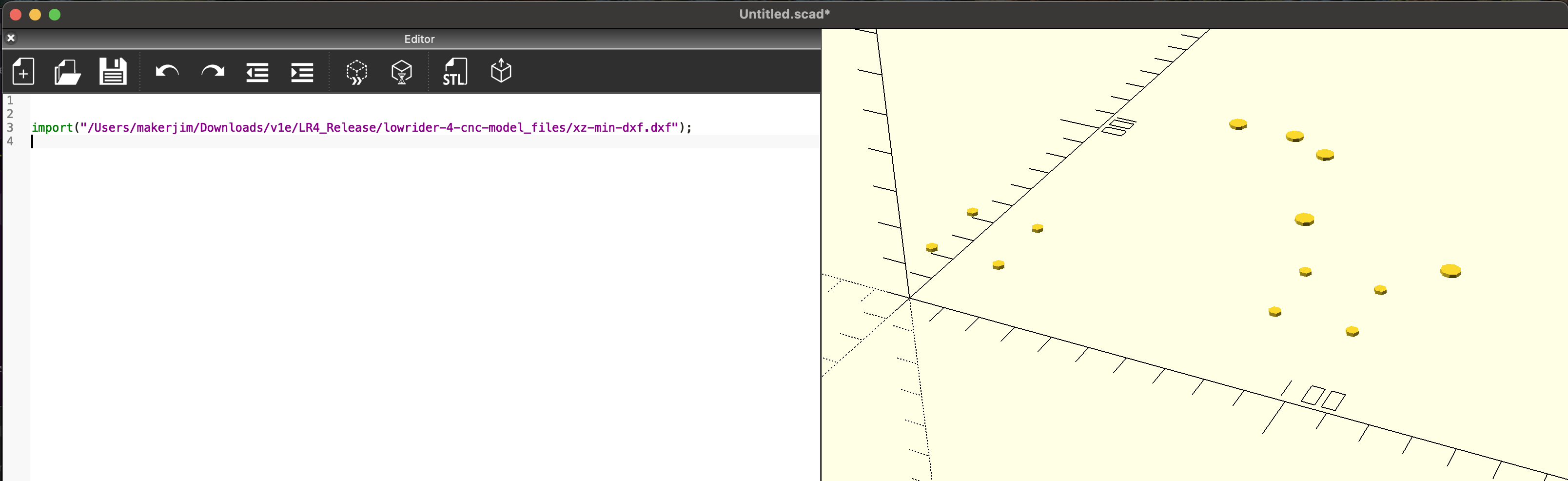
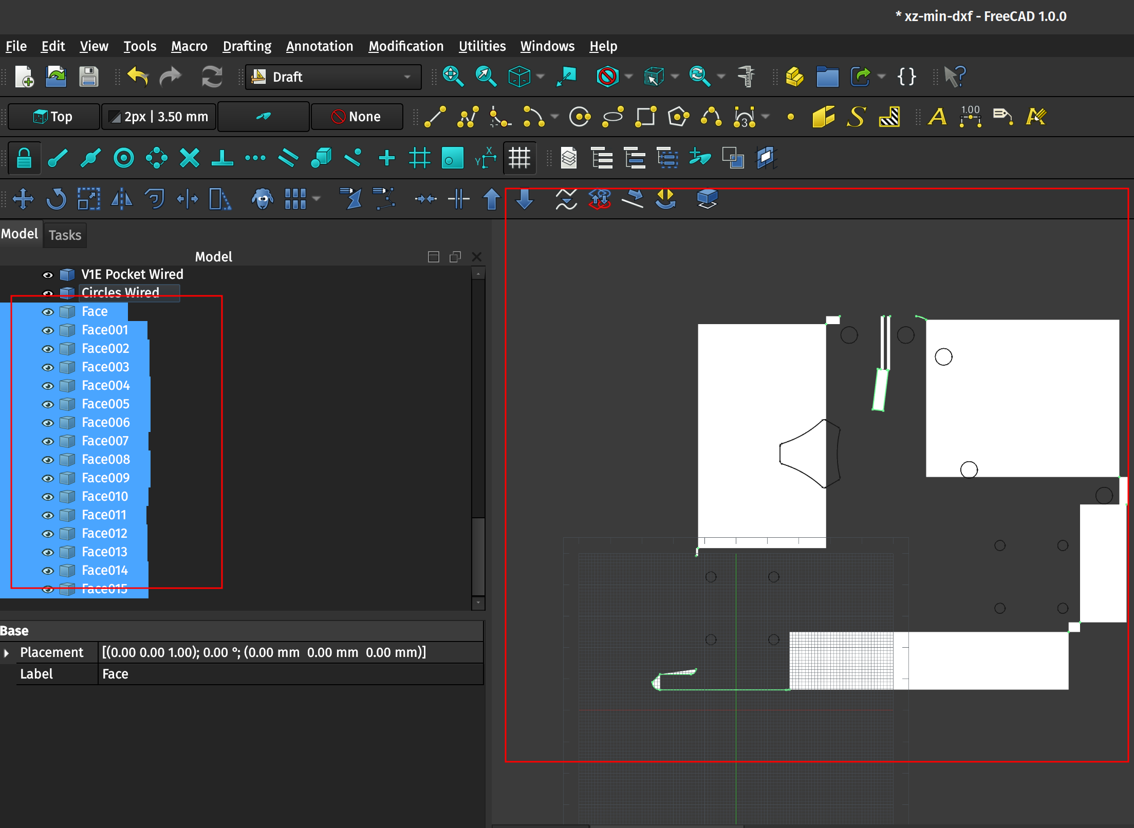
If you try to upgrade all of the shapes in the Outer Contour group you’ll initially get a listing of many Wires. If you then attempt to upgrade those many wires into one object (presumably we intend to end up with a Block just like for the others) you’ll instead end up with Faces and a very strange visual result.
2.2.1 Eliminating overlapping shapes
I realized after looking more closely at the outer contour shapes that there are duplicates in the listing for each edge/line. You can see this more clearly by undoing the prior upgrades, going to the shapes, and making a single line invisible using the Draft workbench and the View > Visibility > Toggle visibility (shortcut Space bar) menu item. You’ll see that the line is apparently still there, but if you click then on the still-visible line it will select a different object in the Model listing. In other words for whatever reason, when importing this particular DXF file there are basically two complete Outer Contours on top of each-other and directly overlapping.
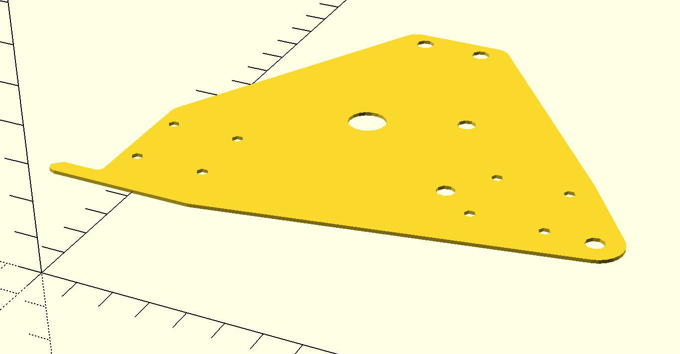
You can eliminate these line overlaps by going through all objects in the outer contour and deleting one of the overlapping shapes. The easiest way to do this is just to go through them and alter the visibility of a shape using the key or the eyeball icon next to the object, and then selecting the remaining item/shape in the same spot and hitting to remove it. If there is no overlapping item below the original you either already cleaned up that line or there’s just not one there. Once done with this step you should be able to upgrade the remaining objects into a Wires and then once more into a Block of wires without any of the Faces appearing. You can quickly move the camera to an item in the Model list using the View > Standard views > Fit selection (or right click in the model view window and select same, or use the shortcut V, S).

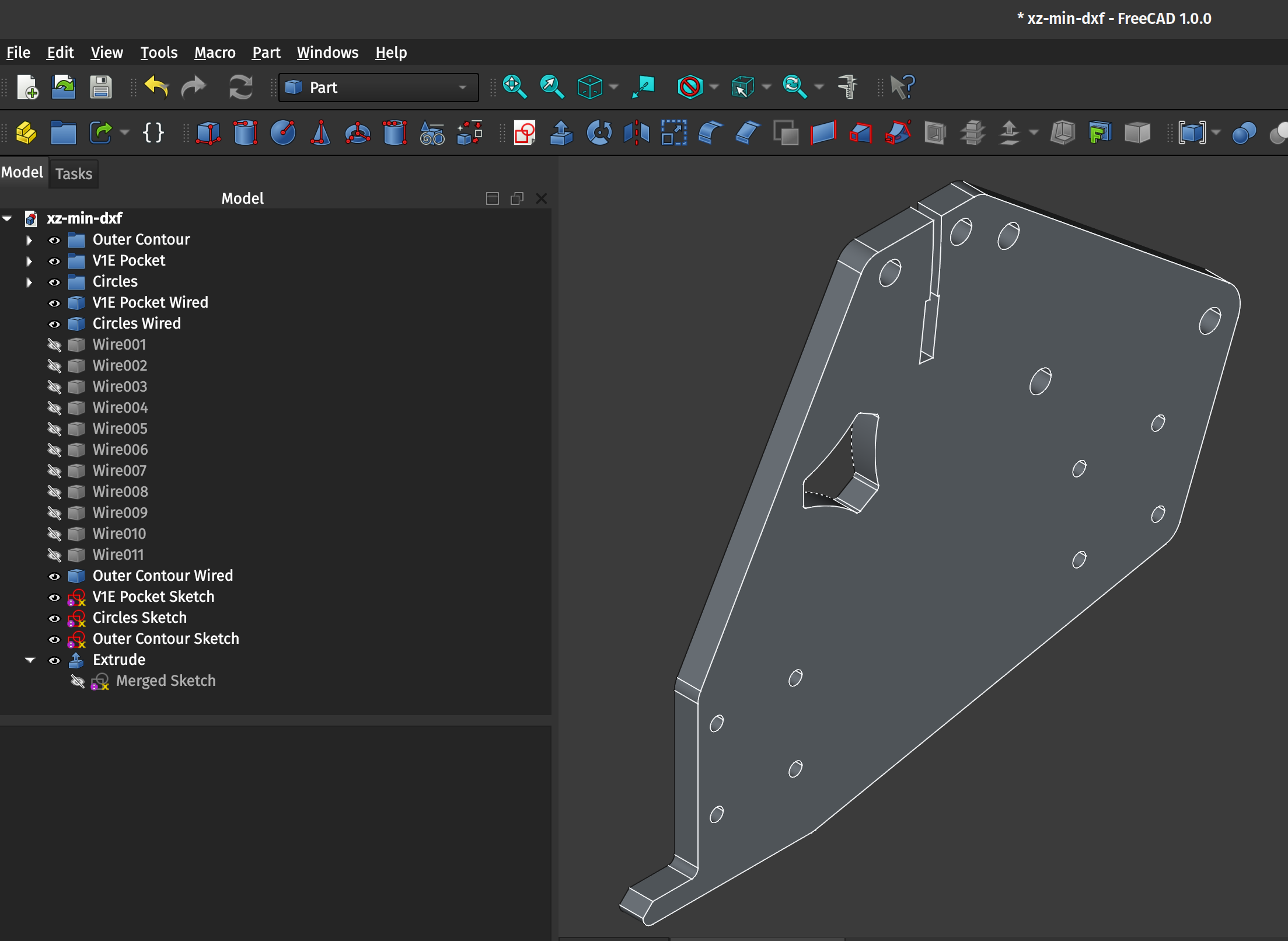
2.3 Draft to Sketch, Sketch Validation, and Extruding the part
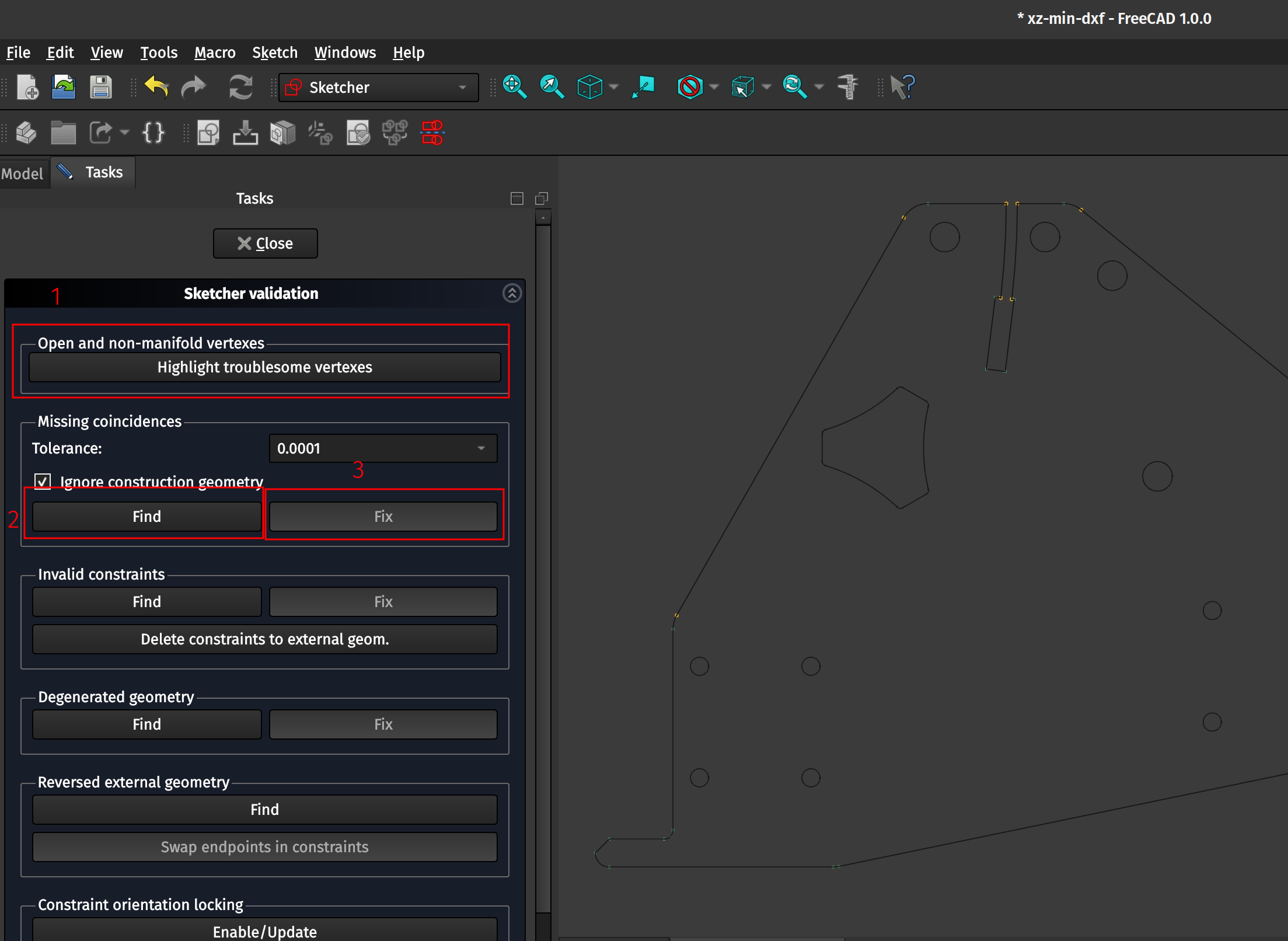
Like before, you can use the Draft to Sketch tool and the Validate Sketch tools in the Sketcher workbench to fix any non-coincident points or otherwise problematic vertexes. You can then merge the Sketches into a single Sketch object and move to the Part workbench’s Extrude tool to finalize the shape! The only Sketch which had troublesome vertexes was the Outer Contour, which makes sense as we probably deleted some lines which were in alignment with other lines (but which otherwise looked to be completely overlapping from our zoomed-out view). Automatically fixing the Sketch works the same as before.
You can then Merge the Sketches, switch to the Part workbench, and extrude the part! Do the same as before and use File > Export to export to an STL and you’re done with both plates! Hooray!