It runs on Linux without problems. 
I totally agree, It would be great for most simple things. You are already very close, just needs a little refinement.
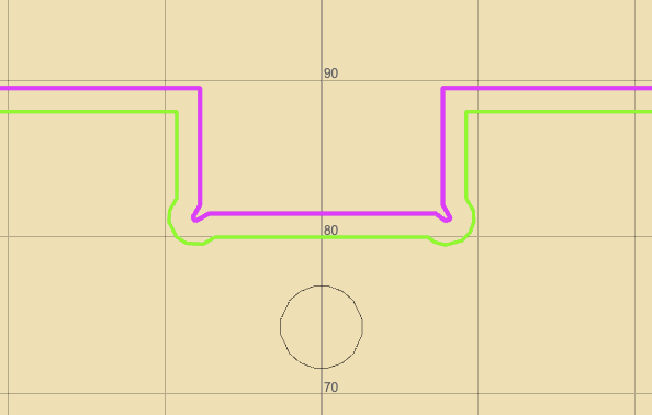
I have increased the svg and dxf conversion resolution it is now at 0.1mm was at 0.5mm before. I now see the relief pockets from the struts file. I also adjusted the import scale to match the viewbox if the svg file is an unknown type which was the case with your strut file. I was using the wrong pixels/inch so the import was too small. The slots are now about 18mm as you had indicated and this is the path for a 3mm end mill. These are exactly the types of edge case I am trying to find as I had just tested with illustrator and inkscape was not expecting custom svg generation tools.
2 Likes
Is it a huge performance hit if you up the resolution a little more? People try to get under a 0.1mm accuracy pretty often. I think for most things 0.1 would be fine but for the edge cases and large radius curves it might show up.
1 Like
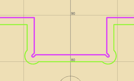
No real performance hit. There is an setting in the options menu at the top right where the tolerance can be set. I have now defaulted it to 0.01mm, but you can adjust to meet your needs. Here is what the path now looks like with the 0.01mm setting. The pockets are now smoother arcs.
6 Likes
Anyone else given this a try yet?
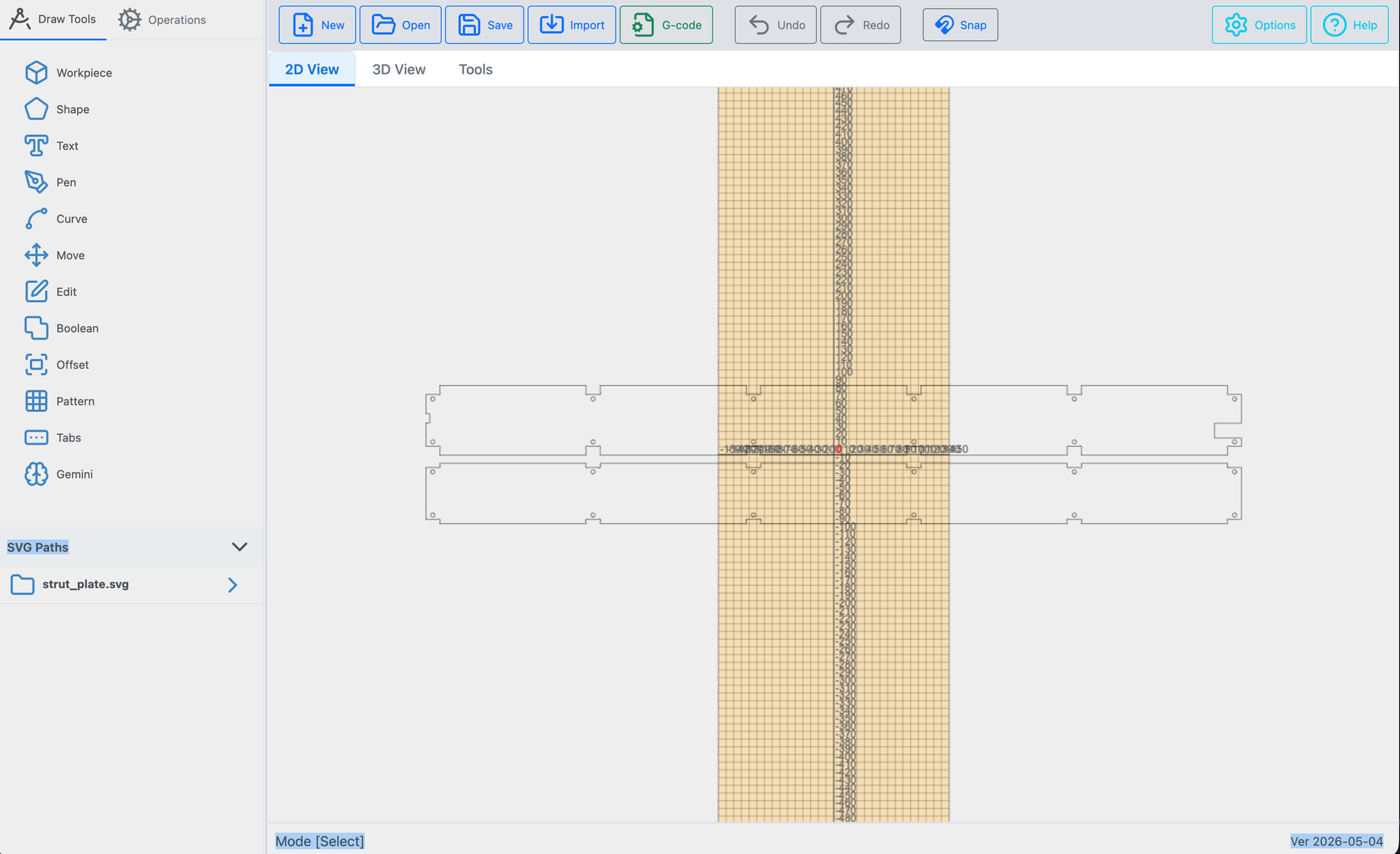
I opened it and fiddled a bit. I tried to load the strut plate SVG design from Jamie’s generator that we made for the RMRRF LR4.
It doesn’t appear to have any way to reorient the input SVGs and I couldn’t figure out how to easily rotate a path. I also couldn’t figure out how to make the holes be a pocket or drill operation, kept making a mess of it.
Mostly due to not being able to reorient the SVG to match the rough size of my small LR4, I gave up.
1 Like
There are are a couple of ways to rotate an svg image after import. You can drag over all the paths to select them and then use the rotation handle that appears on the selection. Note you need to on the draw tab not the operations tab to modify paths.
You can also use the move tool in the left panel (maybe I should change the name to Transform) and then drag over the paths to select them. Then the rotation angle can be entered in the properties dialog or the rotation handle can be used to free rotate. The paths can also be moved, scaled or skewed.
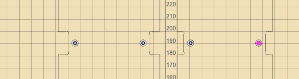
Not sure what the issue with the drilling was to drill select the drill operation and then click on an empty spot to drill a hole there or click on a circular path to drill out the selected circle. You should use an end mill for a hole larger than the diameter of the bit or a drill tool if you just want to dill a hole of the drill size. A drill bit will use a peck drill strategy and a hole larger than the bit will use a helical drill operation.

2 Likes
And it shows the dimensions, that is nice.
This seems pretty full-featured already. Shoot if you could figure out v-carving you would be giving millmage a run for their money.
1 Like
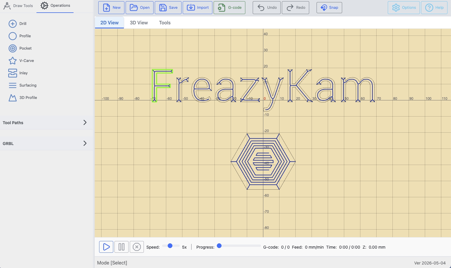
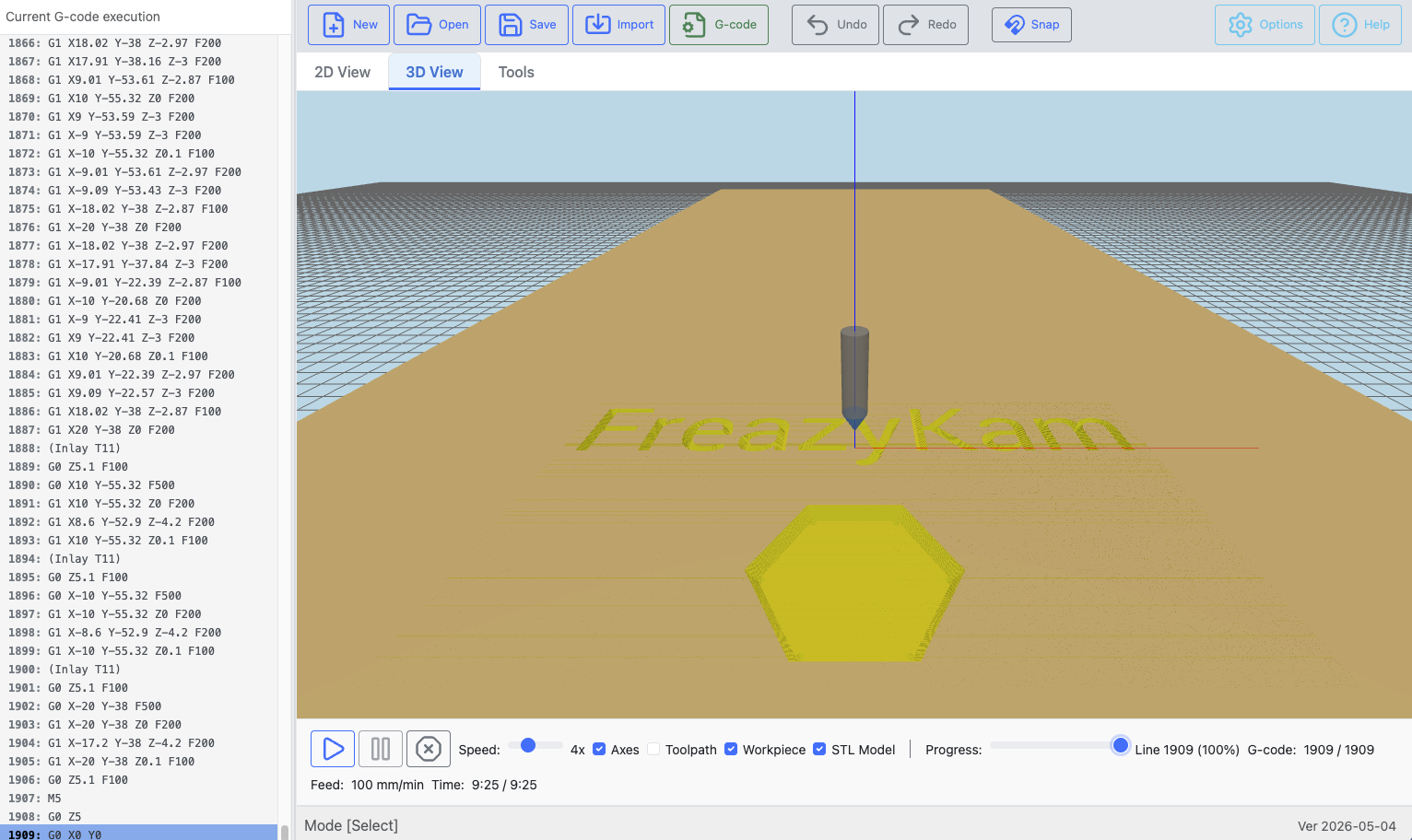
Thanks, it already has v-carve support. Here are some tools paths on text and a polygon. Followed by what they look like in the 3d simulation. This was created with the built in text and shape tools with no svg import even needed.
Nice, do inlays next.
I just played around trying to setup a surfacing toolpath but noticed that the XY feeds don’t get updated after the plunge and stay at whatever the Z feed rate was during the plunge. You’ll want to update that.
I setup a new tool, surfacing bit with XY feed of 3800 and Z feed of 25. The only reason I caught it was watching the 2D preview simulator and noticed that it traveled fast to the start point, then plunged at the slow 25mm/min rate and never sped back up to the proper 3800 feedrate. Here’s a snippit of the gcode it generated:
G0 G54 G17 G21 G90 G94
G21
M3 S10000
(Tool: ID=5 Type=End Mill Diameter=25.4 Angle=0 StepDown=4.75)
(Surfacing T2)
G0 Z5.1 F25
G0 X610.06 Y1245.2 F3800
G1 Z-0.5 F25
G1 X635.2 Y1220.06 ****(It should’ve included “F3800” here)
G1 X635.2 Y1194.91
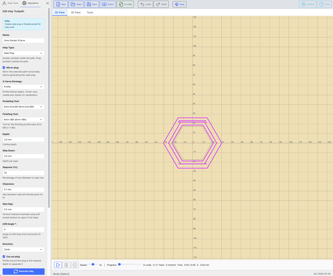
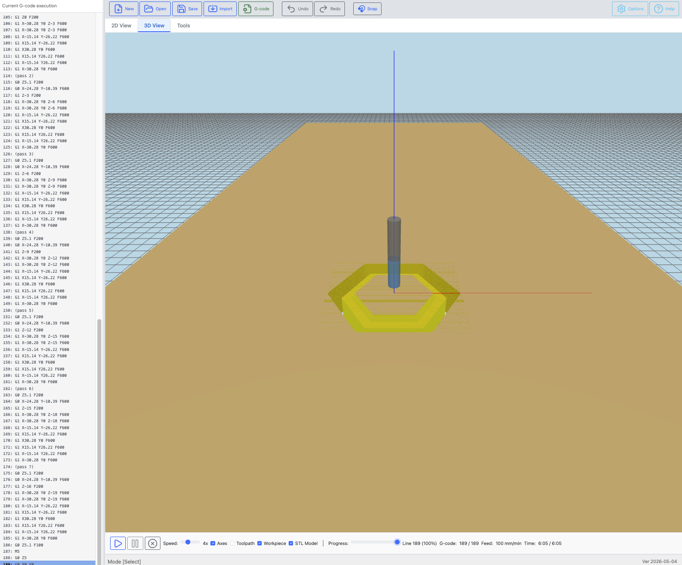
Inlays are also already done, here is the screen shot for the male plug for the above female inlay of the polygon. You can see all the inlay options in the side bar. The male plug can also be mirrored in X if it is not a symmetrical shape.
4 Likes
Thanks for catching that error. I removed the duplicate feed rates for each gcode line in one of the later optimizations and i guess I removed more than I should have. I will take a look and fix when i get a chance.
1 Like
Wow, I really need to check this out soon. Sounds great!
I have added the fix for the surfacing feed rate. The gcode should now look like this. Looks like you have a pretty good machine if you can surface at 3800 mm/min I am not so lucky. Glad you caught it in the simulator before you tried an actual cut.
G0 G54 G17 G21 G90 G94
G21
M3 S18000
(Tool: ID=1 Type=End Mill Diameter=6 Angle=0 StepDown=5)
(Surfacing T1)
G0 Z5.1 F200
G0 X-153 Y103 F600
G1 Z-1 F200
G1 X153 Y103 F600 (this was missing before)
G1 X153 Y98.5
G1 X-153 Y98.5
2 Likes
Since surfacing only takes off 0.2 to 0.5mm in MDF you should be able to run it between 5000 and 8000mm/min. There is basically no load on the cutter and if you go more slowly, it’s getting hot. 
1 Like
That’s awesome, what a quick fix! So far I like the interface well enough, need to play around some more. I’ve been planning to surface the spoil board and it was something simple I could try without having to import files.
1 Like
Thanks, you can also draw simple shapes and pen tool paths and text without needing to import any svg files. As this is still beta code please perform at least a partial dry test before any real cutting. I usually just raise my Z height off the spoil board and zero it out to do my dry run test.
2 Likes
Dang, this is getting good fast.
Any way to add dimensions to the pen tool points? If you had dims, this would be a great simple CAD substitute.