Hi Everyone,
(so some of you might be asking "what the hell is he up to now, just cut some wood FFS. Well I did and as I am using a very small area in my brothers work shop, he got a little upset at the the dust all over his tools, new race motor, turbos, Brand new e-waste gates and other expensive stuff for his stupidly fast Lotus. Hence, the vac project has been brought up to the top of the list…)
Well, my day job is home automation, but it seems I work in a company that sells Whole Home Vacuums as well. (I am sure i mentioned this before, Oh well, Catchup time.)
So these vac’s are good for standard stuff, but once I added the Cyclone, there is not much flow / pressure. I don’t have the space (or $$) for a high volume system, but like I mentioned before it seems I work at a place that has lots of the old units “from upgrades”
So a bit of vac anatomy.
motors, there are two basic types “Flowthrough” ( where the “dirty” air flows through the motor to keep it cool) and bypass (where the “dirty air” is ejected out the side and a separate fan is used to keep the unit cool).
Flow through
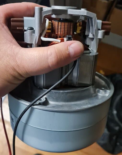
Bypass
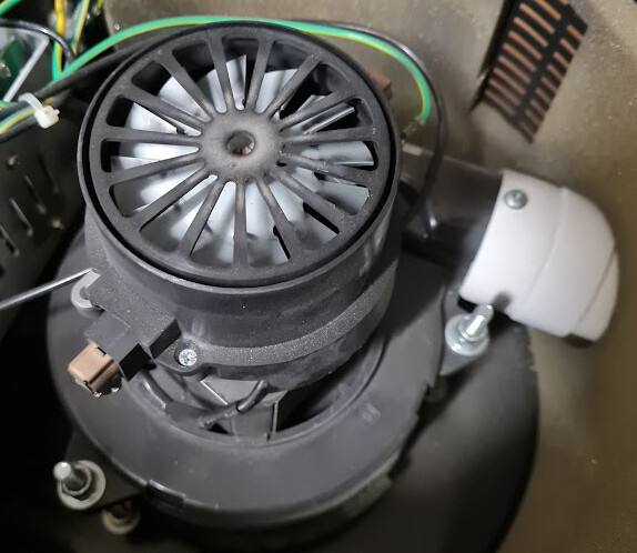
Now the average small home vac has one of these motors, Like the one above, then you have the largest vacs with 2 motors
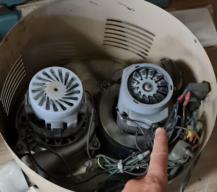
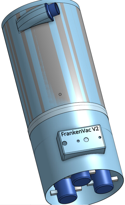
I would like to introduce the FrankenVAC
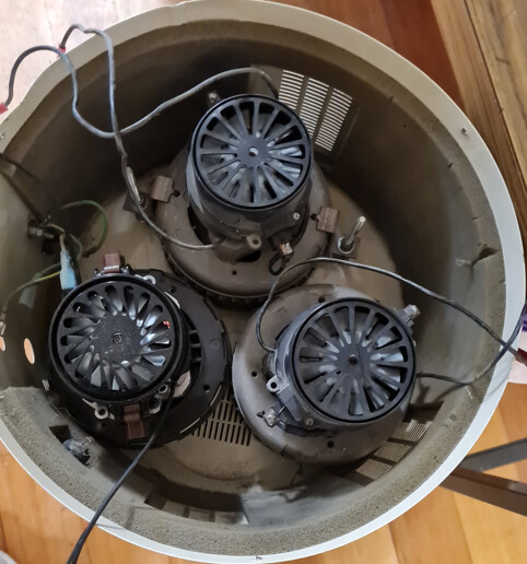
I got this idea from a Youtube show “hooked on wood” where I saw him making a system that was based around a 3 motor VAC system, CAMVAC. While watching it I had the idea to use some of the parts from work and make my own.
So a motor driving board, that you can barely see in the top left of the first picture, can control up to 2 motors, safely… NO, I am not going to dodge up some terminals and plug all three motors into one second hand board and turn it on to see what happens (for those that like to know the answers to questions like that, the magic smoke got very angry and spat the innards of a cap across the room and dumped the safety switch, or that is what i… think… might have happened…)
Sorry that is what I ASSUME would have happened as i would not be silly enough to do that… (magic smoke smells really bad)
So my version, After consulting with the relevant electrical engineers, is going to use two boards. One board to start two motors and the second board to start the single motor.
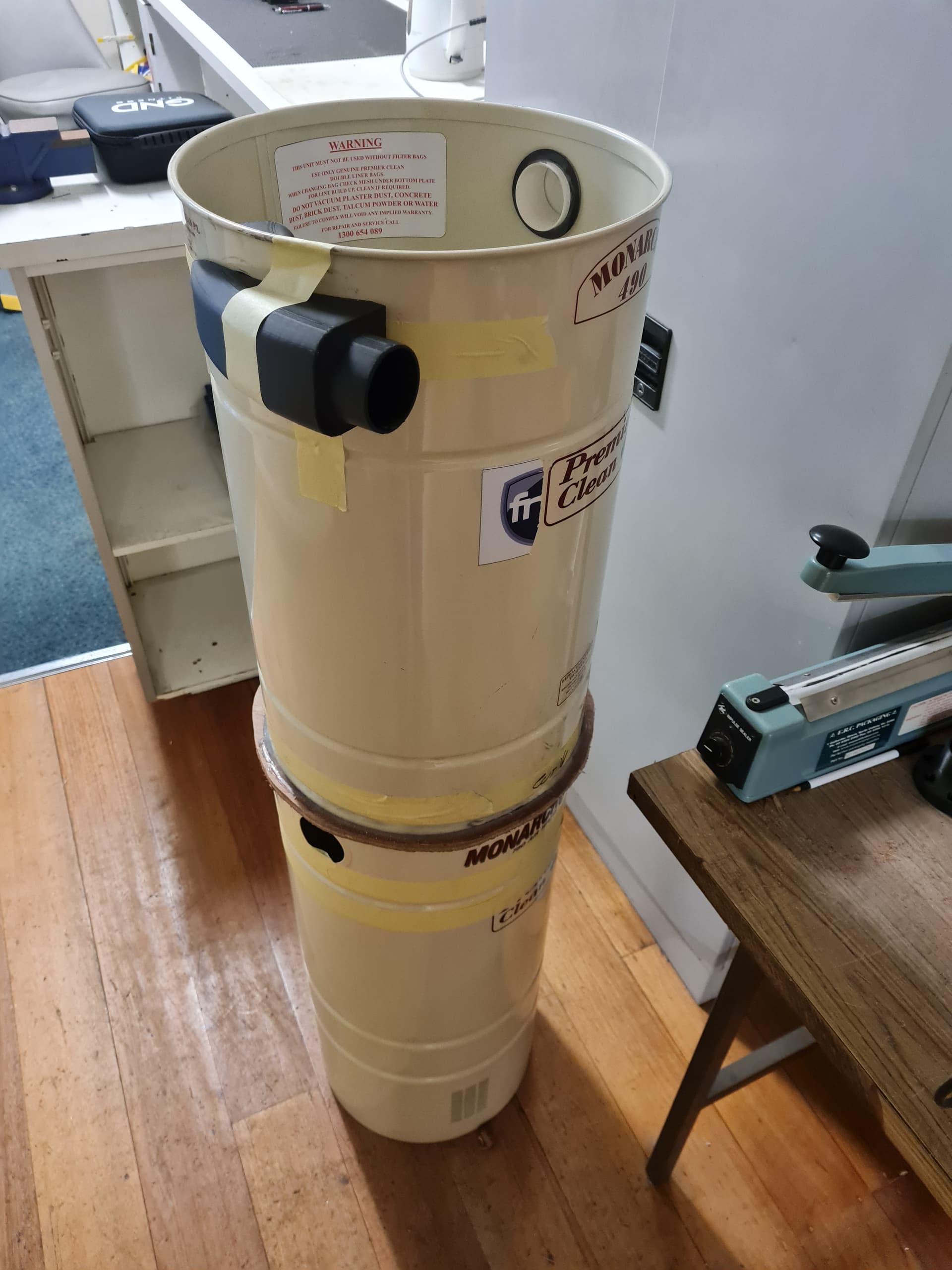
As i have access to quite a few of these old “upgrade” units, most of them have blown motors etc, I am going to create a Frankenstein VAC with its own cyclone barrel and eventually magnetic couplers.
I am going to cut down the “drive” unit so that it is just big enough to fit a bag attached to the central vac pipe, (you will see the idea in the next pictures), to protect the motors. This area is only looking to be about 500mm high. Just enough for the bag to inflate.
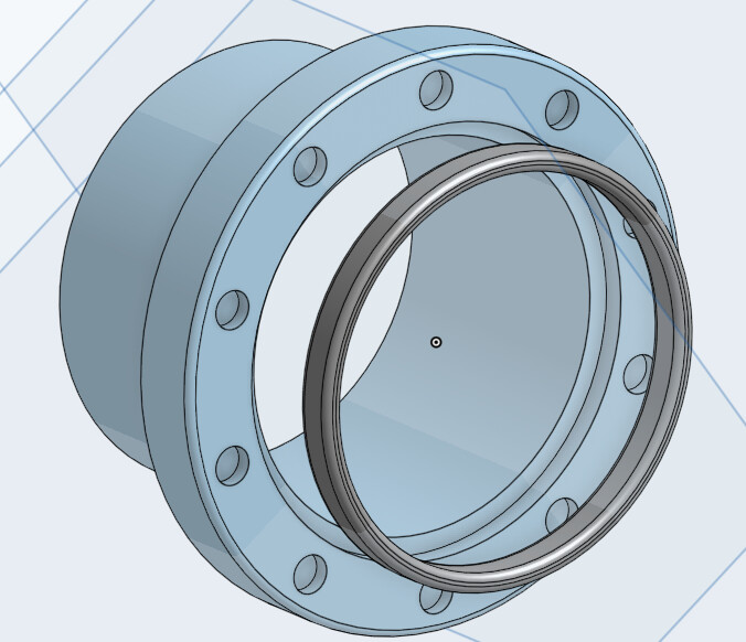
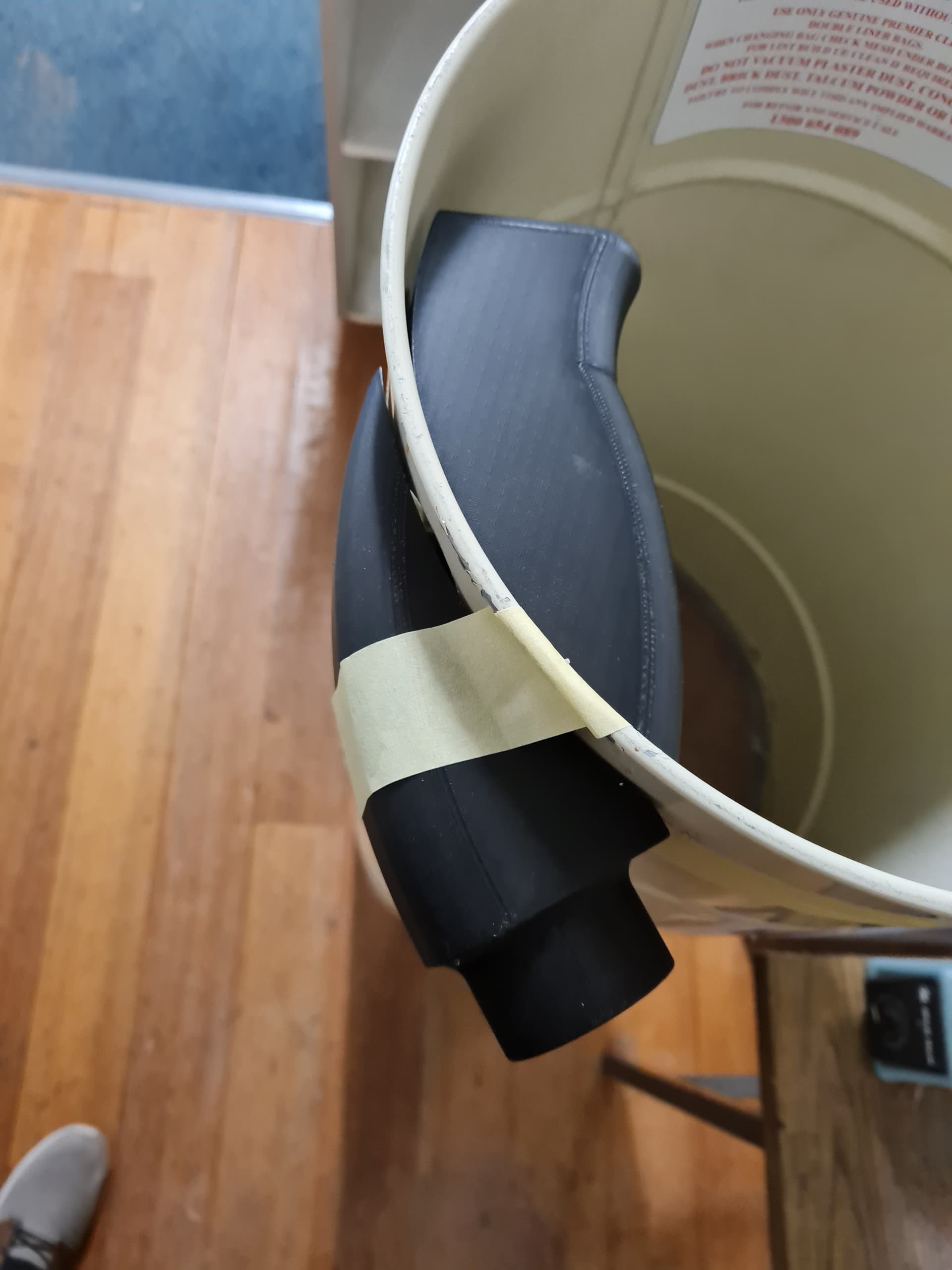
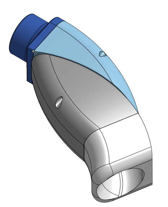
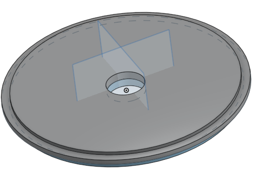
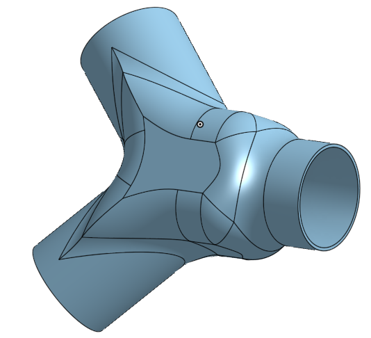
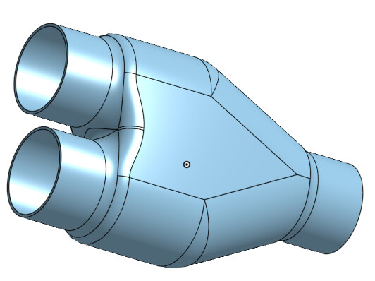
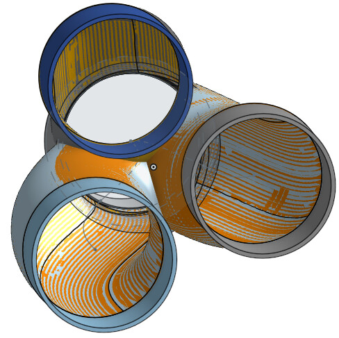
I have designed this to adapt onto the side of the barrel to induct the cyclone.
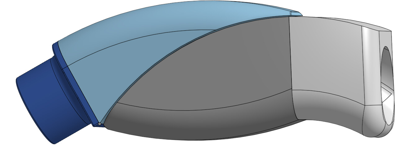
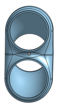
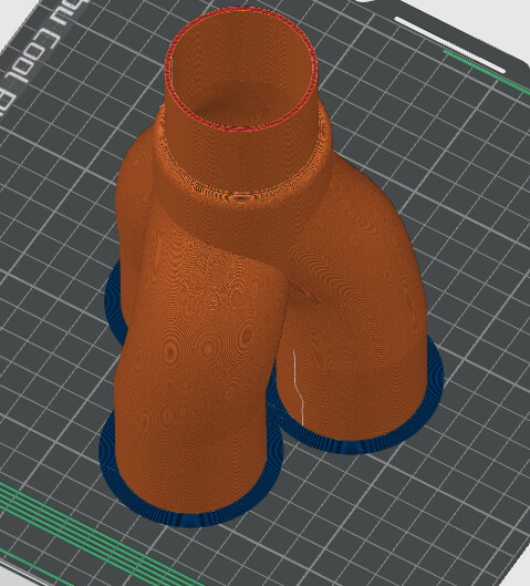
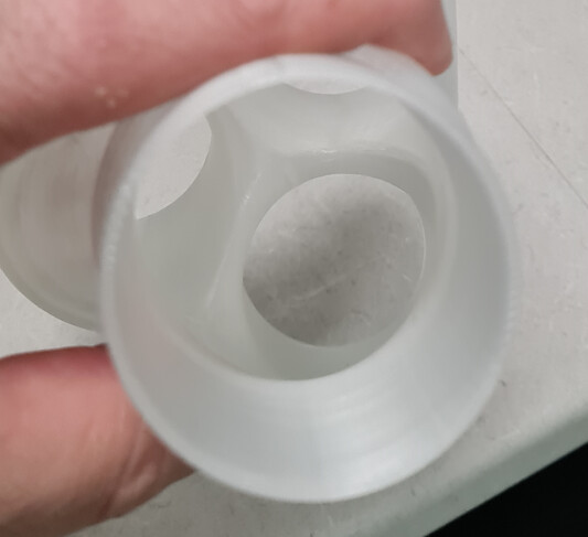
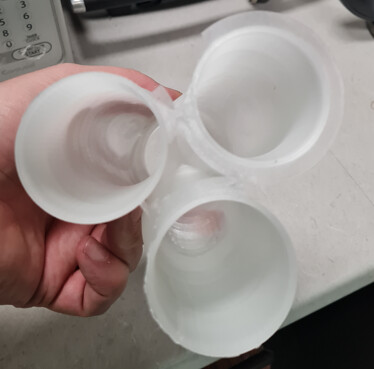
Its in 4 parts to make it easier to print and attached to the barrel it should look like this
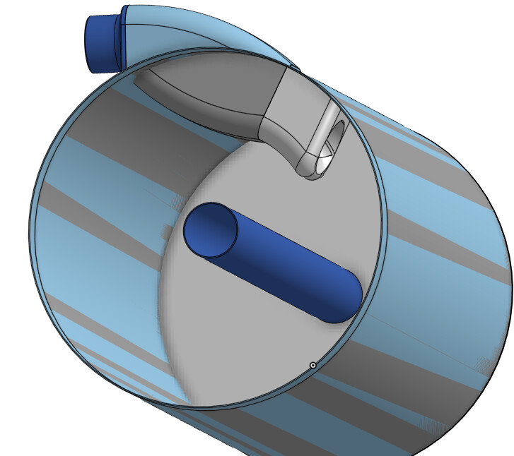
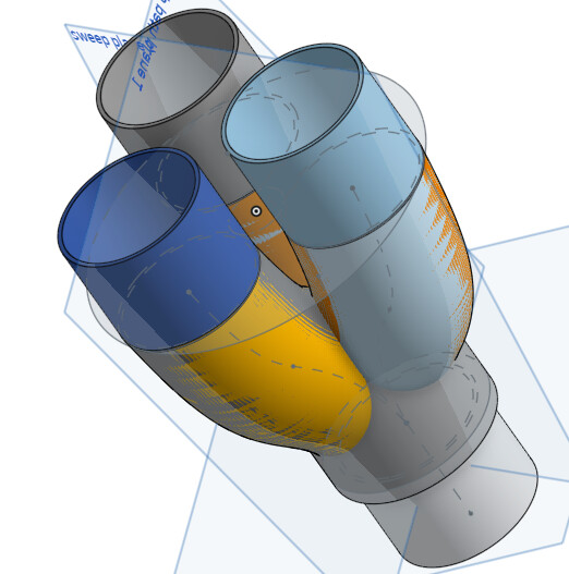
the AIR path is as smooth as i can get it with my skill.
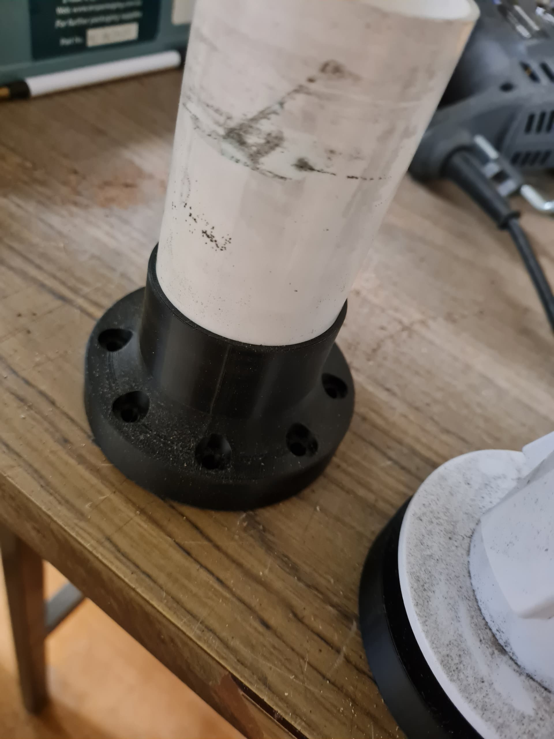
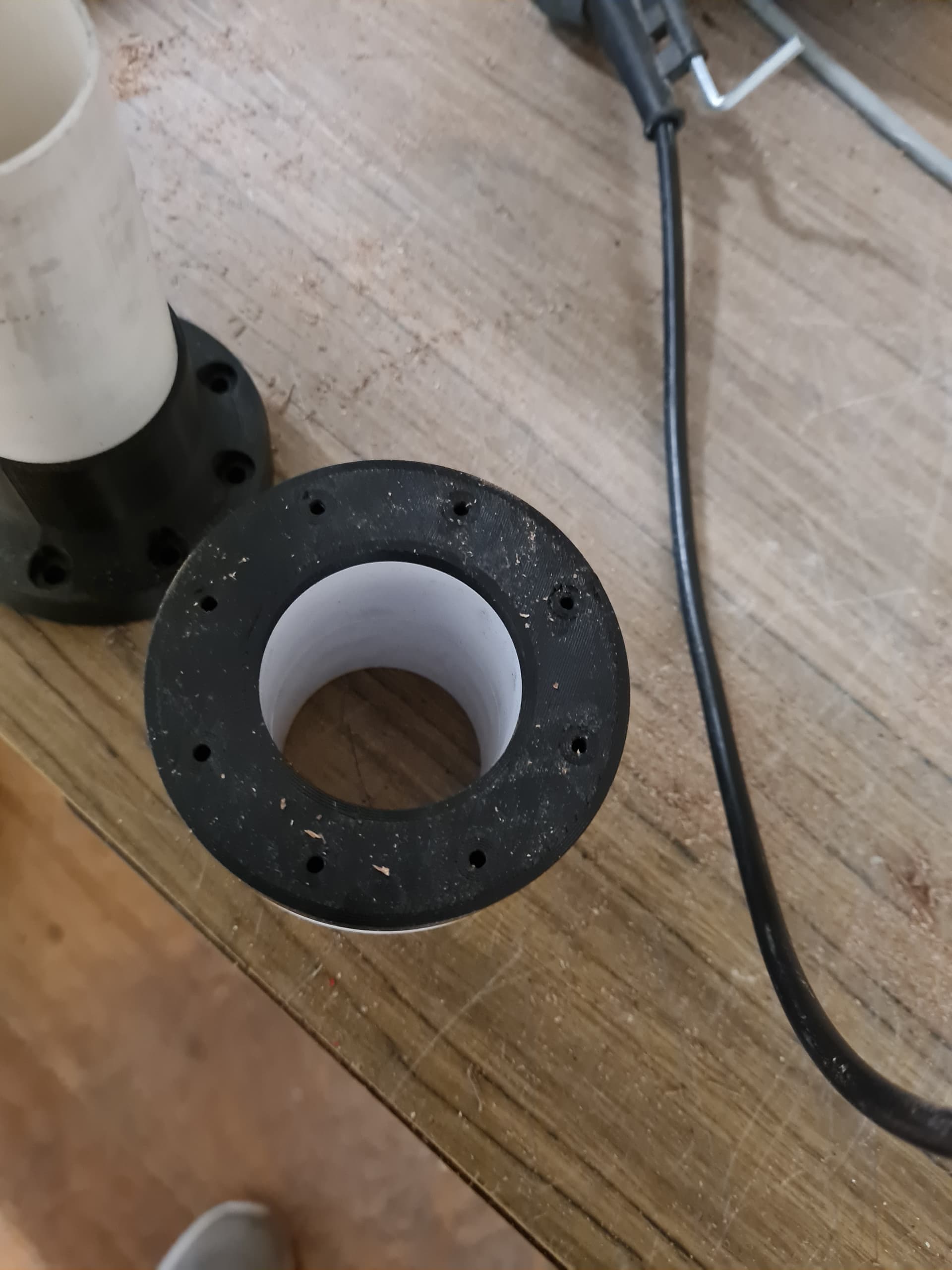
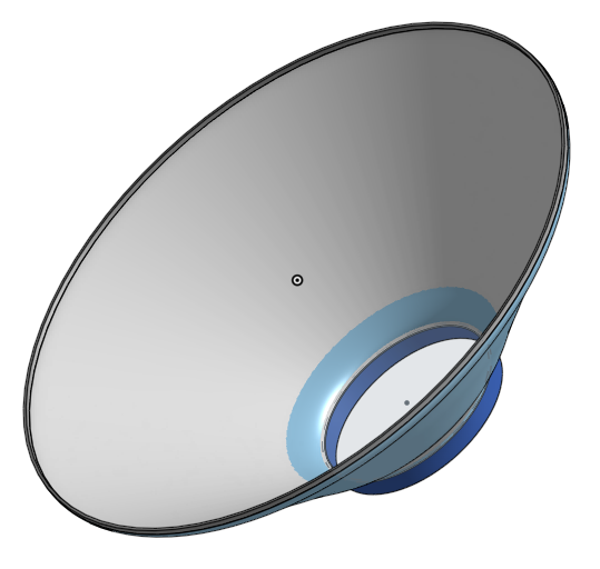
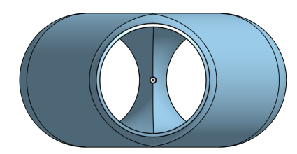
The barrel image shows the central tube, which extends to about 20mm from the top (and has a “spear” bag holder on the underside to hold the bag to protect the motors) so hope fully the smooth-ish entry and centrifugal motion generated will be enough to get rid of 90% of the dust, the normal vac bag will grab the rest.
To join the drive unt and the collection tub, as they are the same DIA, I am just going to pop rivet a collar around the outside of the collect unit, then bend inwards about 20 mm of steel on the top of the cut down drive unit, adding some weather seal squishy tape to seal the vac pressure. The collection unit should just slide over the drive unit and sit on the underside of the collection unit bottom. That should make it easy to remove the the collection unit and empty it.
I might have to go the magnet route for the collection hose to make it really convenient, but that can be version 3. lol
Oh and I am going to be using a mix of 38mm (standard vac hose, as I can get it from work…) and 51mm hose from the CNC. The inlets on the collection barrel are 51mm, so i might have to cad up a 51mm to 38mm Y.
More to follow