Add something like ESP32 CAM mit OV2640 Kameramodul-Kit 8 MB PSRAM 2,4 G WIFI 3 dBi Antenne 66 120 160 Grad 650 nm 850 nm Nachtsicht 2 MP 24Pin - AliExpress 502 into the shoe too?? ![]()
Those little boards are rad, Heffe sent me one, that led is extremely bright, have not tried the camera yet.
whoa, those are cool, have you used them? I wanted to make some lights, maybe I will try them ![]()
Nope, never tried one.
Make sure to match your input voltage unless you plan on a different power supply.
This ↑
I think to make light worthwhile, there would need to be a version of the dust shoe that could take clear bristles. At this point any solution would only be good for times I’m not using the dust shoe, so probably not worth it. I carry a flashlight, and if I need to look under during a hold, I just illuminate it from the front. The beam lights do let me see the cut quality and some types of problems and they’re easy.
Ohh, that’s just a logic level shifter. The ESP32 is 3.3v but the LEDs want 5v on the data pin. So, that is just converting it.
I got my LED strip today. I’m going to try it without it first since it might work. Sending 3.3v to 5v generally doesn’t hurt things, but sending 5v to 3.3v devices can get you in trouble.
It should work. That’s how my LEDs are currently wired. Literally 3 breadboard wires and a buck convertor with some 18g power wires. I put it all in a gladware container taped to a strut. Super low tech enclosure but thought it would reduce the dust. Always intended to get back to it…
Since at this point I’m only doing white, and I use WLED to adjust for the temp I like, it works for now. I am concerned that if I start trying to change the colors, or run multiple strands it may start to show its weakness.
Just FYI… (more for everybody, not just directed at you ![]() )
)
The WS2812B can kinda get away without the level shifter sometimes… but it’s an absolute must with WS2815.
The WLED guys will tell you that you need it for both, but the 2812s I’ve seen sometimes be ok without it.
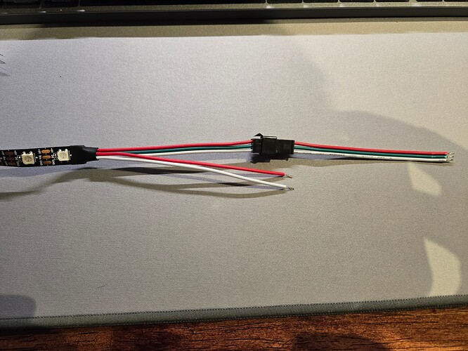
I’m trying to figure out how to wire this thing. My electronics knowledge is quite basic. It looks like I should have a 1000uF capacitor between 5v and ground, and a 470 ohm resistor between the ESP32 data pin and the strip. That’s fine, I have those. There’s one set of wires with +, -, and data, then another set with + and -. I get that the set of 2 is for powering the LED string and that the data pin goes from the ESP32 to the strip. I’m just confused what I do with the + and - that goes along with the data pin.
Then technically, I should be able to power the ESP32 directly from the same 5v power source, but I’m going to be connecting via USB for flashing it. So, I’m not sure if I can just power the ESP32 via USB for now? What happens if I connect both?
On the software side, I have code that connects to FluidNC via TCP/telnet. I’m getting and parsing the status string to get the status and X position. That was about as easy as it gets. It looks like I’m going to use the FastLED library instead of the Adafruit Neopixel one.
The second set of power wires are for power injection. If you are adding this string to the end of another string, you’d attach the 3 wires to the end of the last strip and inject 5V on the additional wires to mitigate voltage drop. You wouldn’t use them on the first connection, and you probably wouldn’t need them until the run got long enough that you noticed some pixels aren’t quite the same color.
If you have 2 different 5V sources you have to make sure the grounds are bridged common.
LEDs will start to do some funky things if not
Yep, I did that.
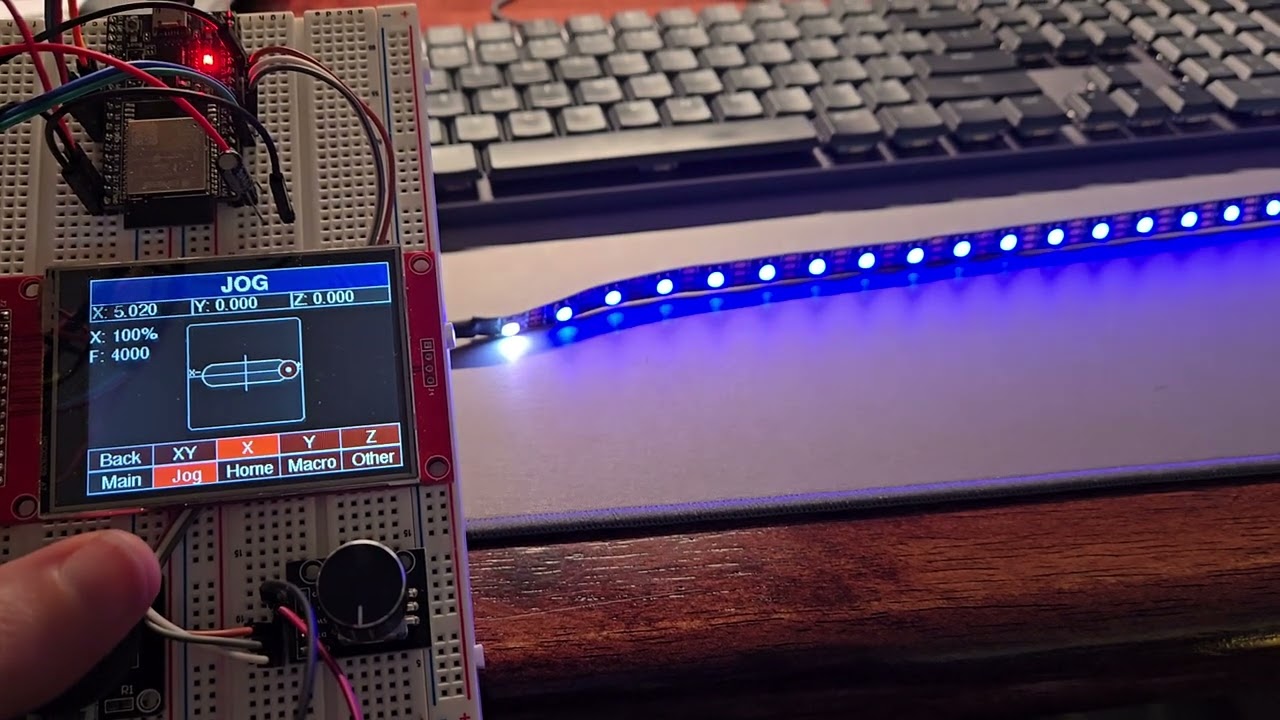
Got it working. Including changing color based on state. In 82 lines of code. This is awesome. Getting the part working that shows them around the core should be pretty easy. I’m over here sitting at my desk with my LR3 in the garage, doing things on my little wireless screen project that changes the state, and watching my wirelessly connected LED strip update.
This is bad. This is very bad. Is there an LEDATTA (LED All The Things Anonymous) support group?
Code
#include <Arduino.h>
#include <WiFi.h>
#include <FastLED.h>

#define NUM_LEDS 60
#define DATA_PIN 16

// Define the array of leds
CRGB leds[NUM_LEDS];

// Connection Info
const char* ssid        = "[WIFI SSID]";
const char* password    = "[WIFI PASSWORD]";
const char* fluidNcIp   = "[FLUIDNC IP OR fluidnc.local]";
const uint16_t fluidNcPort = 23;

WiFiClient client;
bool connected = false;

void processStatusUpdate(String statusString) {
  unsigned int pos = statusString.indexOf("|");
  String status = statusString.substring(1, pos);

  unsigned int pos2 = statusString.indexOf("|", pos+1);
  String mpos = statusString.substring(pos, pos2);
  String mPosX = mpos.substring(0, mpos.indexOf(","));

  if(status == "Idle") {
    fill_solid(leds, NUM_LEDS, CRGB::Gray);
  } else if(status == "Home") {
    fill_solid(leds, NUM_LEDS, CRGB::Teal);
  } else if(status == "Alert") {
    fill_solid(leds, NUM_LEDS, CRGB::Red);
  } else if(status.startsWith("Hold")) {
    fill_solid(leds, NUM_LEDS, CRGB::Yellow);
  } else if(status == "Run") {
    fill_solid(leds, NUM_LEDS, CRGB::Green);
  } else if(status == "Jog") {
    fill_solid(leds, NUM_LEDS, CRGB::Blue);
  }

  FastLED.show();
}

void setup() {
  Serial.begin(115200);

  WiFi.mode(WIFI_STA);
  WiFi.begin(ssid, password);
  Serial.print("Connecting to WiFi ..");
  while (WiFi.status() != WL_CONNECTED) {
    Serial.print('.');
    delay(1000);
  }
  Serial.println(WiFi.localIP());

  FastLED.addLeds<NEOPIXEL, DATA_PIN>(leds, NUM_LEDS);  // GRB ordering is assumed
  FastLED.setBrightness(80);
}

void loop() {
  String line;

  if (!connected) {
    if (client.connect(fluidNcIp, fluidNcPort)) {
      client.write("$Report/Interval=100\n");
      connected = true;
    }
    else {
      delay(500);
    }
  }
  else { // connected
    while (client.available()) {
      line = client.readStringUntil('\n');
      if(line.startsWith("<")) {
        processStatusUpdate(line);
      }
      Serial.println(line);
    }
  }
}
The point is you now can run it in the dark in the garage. You can cover the windows and simulate night during the day and perfect the feel. ![]()
![]()
Something else to think about. There are times that its hard for me to see when lining up for where I want X,Y 0 to be. And something like this would sure make that a lot easier. So I get that it would only be useful for a min or 2 every so often, but in those times it would be worth the hassle I think. I love the lights under the beam, but @dgkeith237 is right they don’t do a lot for right at the bit.
I print clear TPU bristles for my machines (its enough having color options for the PLA, I didn’t want to have to stock and deal with different colors of TPU as well lol) but they are not “CLEAR” by any means. Anything that would be truly clear would still be useless the second you start cutting because of all the dust.
What about just running some LEDs through a gooseneck mount on the core so you can point it where you want?
I guess having something lightweight yet rigid enough would probably be a challenge.
I haven’t read the entire thread but I like where I think this is going. Perhaps the lights could be red when they reach the ends?
And you know those LEDs don’t have to be in strips - so single LED endstop indicators is on the table too.
You’re a wizard Yeager.
Omg!!! That is crazy!!!

