Well, here’s another mishap I figured I’d share for everyone to learn from:
When I first got my M5Dial, I noticed a rattling sound inside the case. I took off the orange bracket on the back of the unit and pried the StampS3 board up enough to shake out a loose screw. I was slightly disappointed in the quality control, but just assumed it was an inconsequential mounting screw for the PCB and carried on.
After getting through the issue I had with VSCode I was happy to have a fully functioning pendant. As I was performing motor direction tests with my new Jackpot board, I noticed one of the connector pins for my pendant had a poorly crimped wire. I disconnected the pendant, recrimped and pinned the connector, and plugged it back into the Jackpot. The pendant powered on as usual, but showed a “N/C” message. I assumed I had accidentally reversed the UART (TX/RX) pins, so again I unplugged the pendant, swapped the pins, and plugged it back in.
This time, the LED buttons on my pendant illuminated, but the screen did not. I checked the back of the dial and noticed that there was a red light on which was visible through the gap near the USB C port. So the device was still receiving power, but was not visibly turning on.
I brought the pendant home and tried reflashing as per the directions from some of the devs on the FluidNC discord server. My computer gave a “Device not Recognized” warning when I plugged into USB. I tried reinstalling drivers, uninstalling the device from device manager and plugging back in, as well as the “bootloader” trick of holding the S3 button and then pressing the reset button on the back of the dial, however I was not able to get the device to be recognized. No recognized device, no COM port, no flashing.
I was at a loss as to what could be wrong, so I decided to open the dial up to check for physical damage. I was curious how to get inside the dial anyway, so I guess now was a good time to learn.
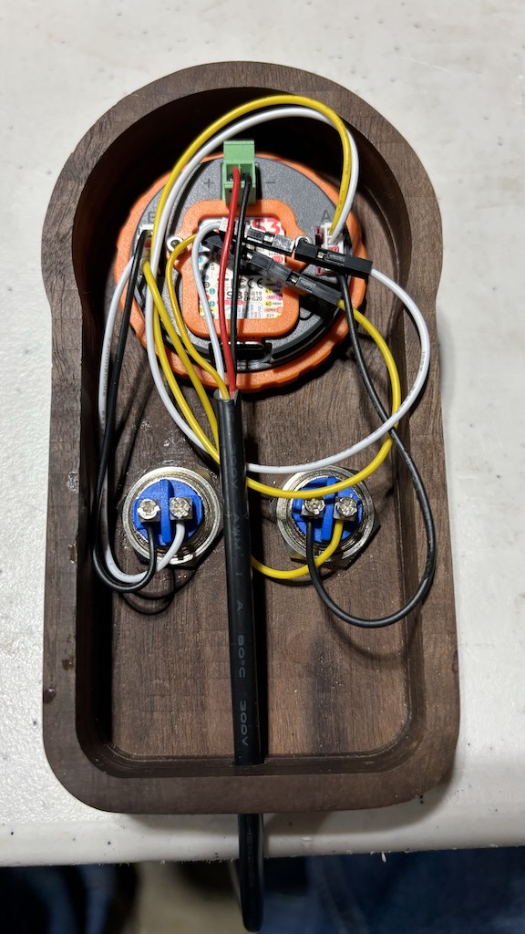
After taking off the orange bracket and carefully prying the S3 board out from its pins, the first thing I noticed was two screw holes. One had a screw, but the other was clearly the origin of the loose screw I found when first programming my dial. I removed the second screw as I presumed it held the display PCB to the main PCB. I found that the orange bezel on the front of the dial can carefully be pried to release the four retaining clips which mount it to the face. After the two screws and orange bezel are removed, you can carefully pry the display straight up, disconnecting the pins between it and the main PCB. The grey outer ring is connected to the central black rotary sensor shaft by four retaining clips. These can be depressed and carefully lift the grey ring off. Next is a floating orange ring with two springs on it, which provides the bezel button spring function. This is not retained and can simply be lifted off. The last step is to remove three screws which mount the motherboard PCB from the grey back case. At this point you could swap out the JST connectors to the more common style if you wanted.
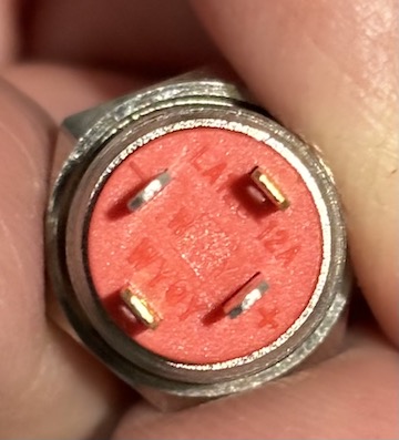
Regardless, I found that the one missing screw was actually missing from a metal stand off between the motherboard PCB and the display PCB, and located very close by… silkscreen lettering of “GND”…
So I’m left with two thoughts: That metal standoff facilitates a connection for the display and motherboard, and the lack of a mounting screw allowed for a slight disconnection with a small physical bump to the pendant, OR that in the process of swapping the UART connection, the temporary TX to TX connection caused damage to the internals of the display. I have never experienced a device actually being damaged by a short mismatching of the UART, but it is certainly possible that the M5Dial is not able to tolerate this.
I would advise caution to ensure you have two visible mounting screws beneath the S3 board on the back of the dial, and to ensure you do not accidentally mismatch your RX/TX wires. As of right now, and as far as I can tell, my M5Dial is dead ![]() I would hate for this to happen to anyone else.
I would hate for this to happen to anyone else.
If anyone has any suggestions, I would be more than willing to try. Otherwise I suppose I will be ordering a new one and taking these precautions while installing. Luckily Digi-Key and Mouser both have much faster and cheaper shipping to Canada!