Not new to 3D printing or building 3D printers but first time trying any sort of subtractive manufacturing or CNC so pretty stoked to get started!
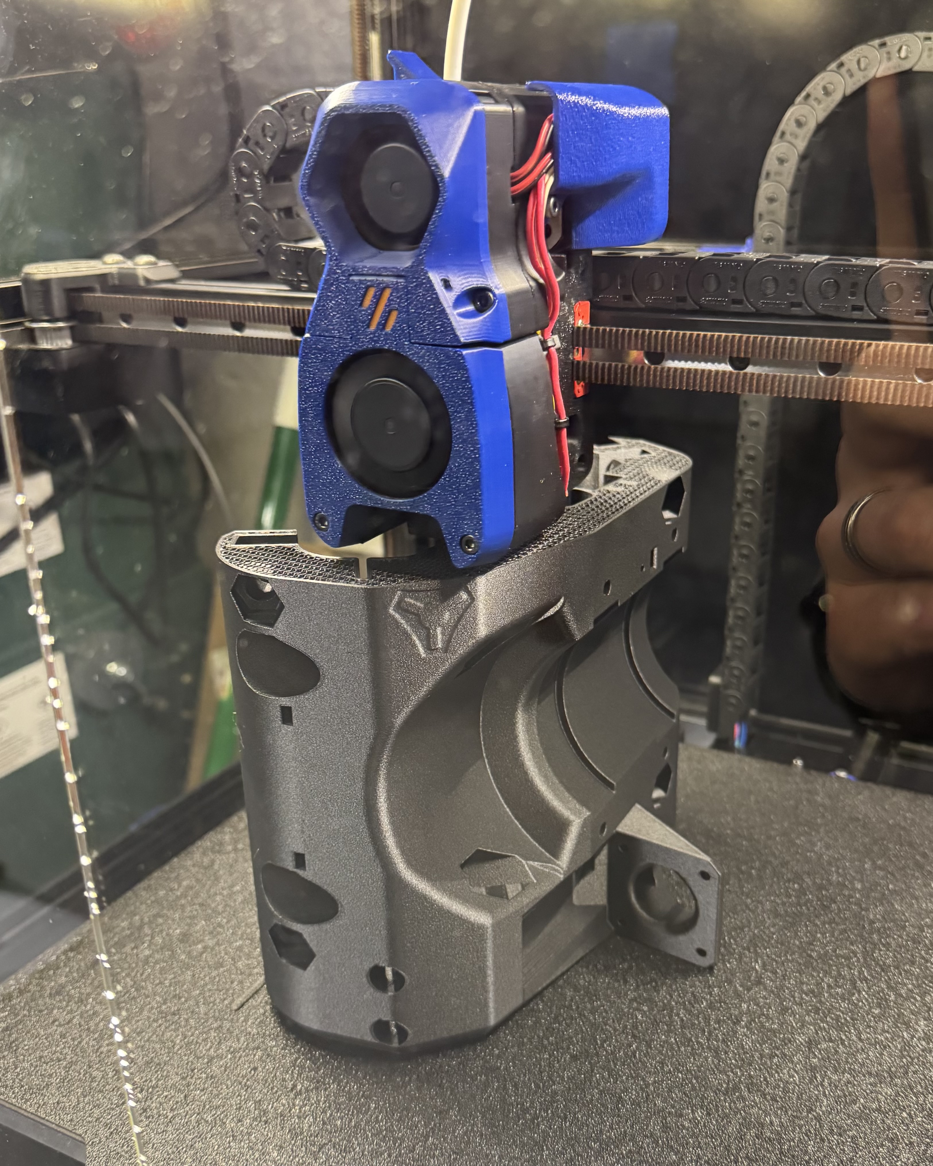
I printed all my parts from Polymaker/Fiberon PETG-rCF08 and was really pleased with how they came out.
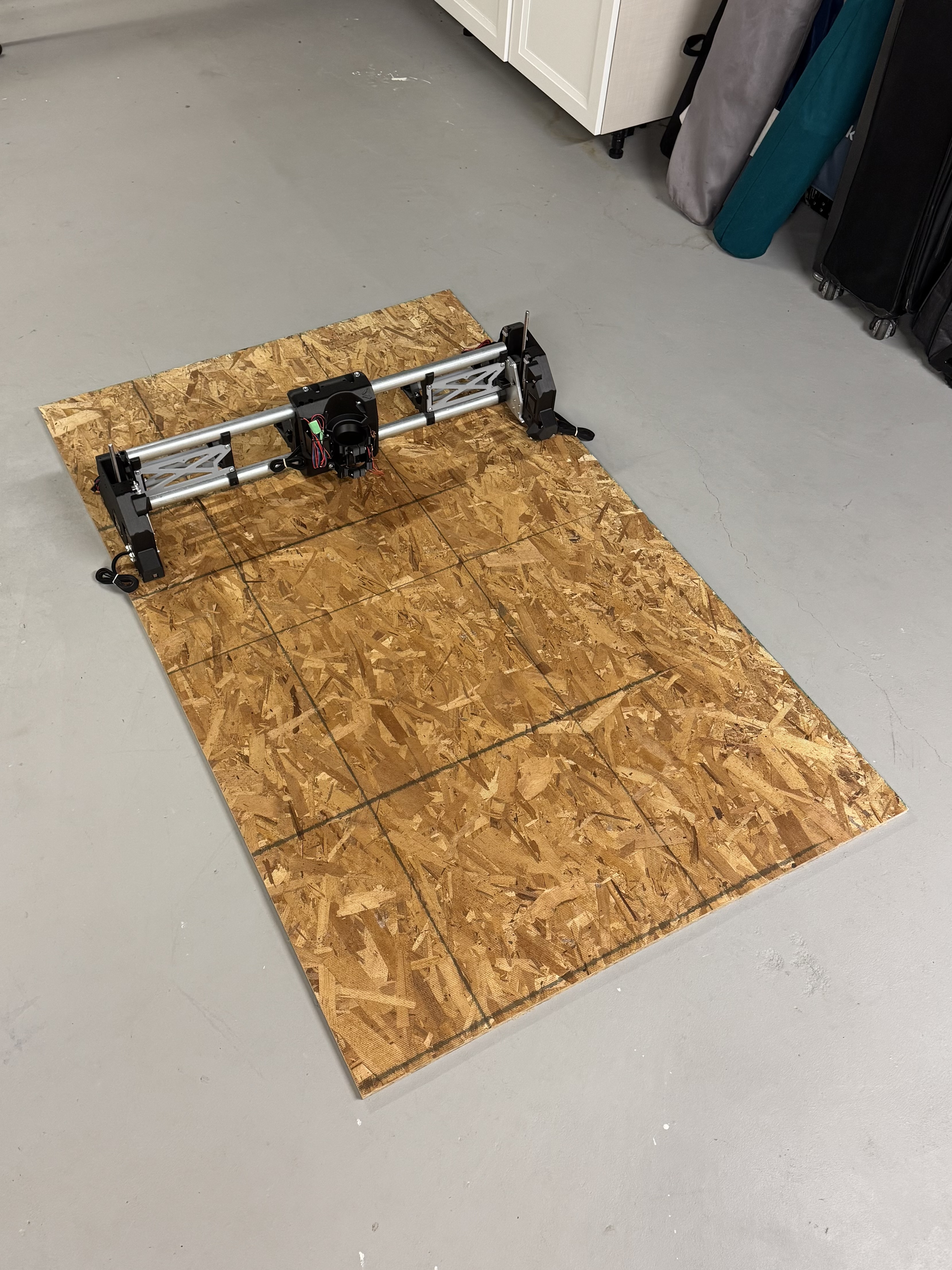
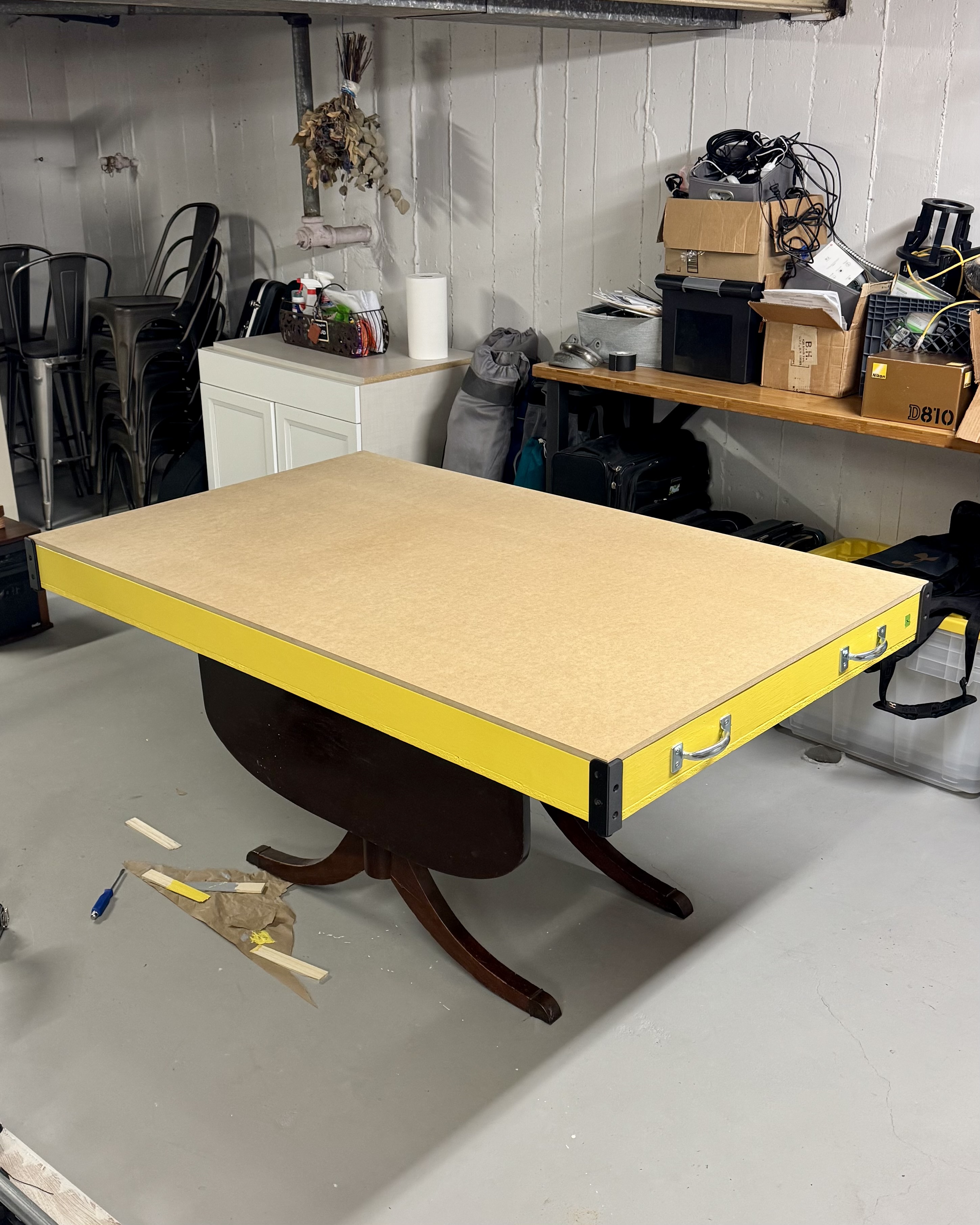
The actual work area is 26” x 50” but I plan on using a 24” x 48” spoilboard. Not sure if it was required but I wanted to have the ability to make a 2’ x 4’ object with some wiggle room for positioning.
Two questions:
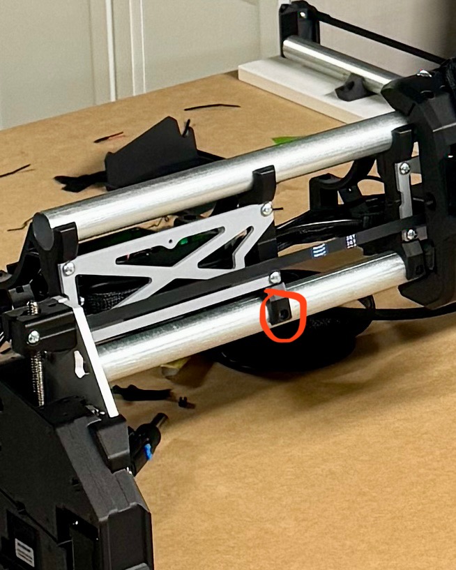
When do the Z lead screw cross tensioner screws get added? The build says to leave them out and then doesn’t mention them again
It’s up and moving but any tips for measuring between the squaring dots? I assume within 1/16” is okay? (1.58mm)
More questions to come I’m sure but the build has gone great so far!
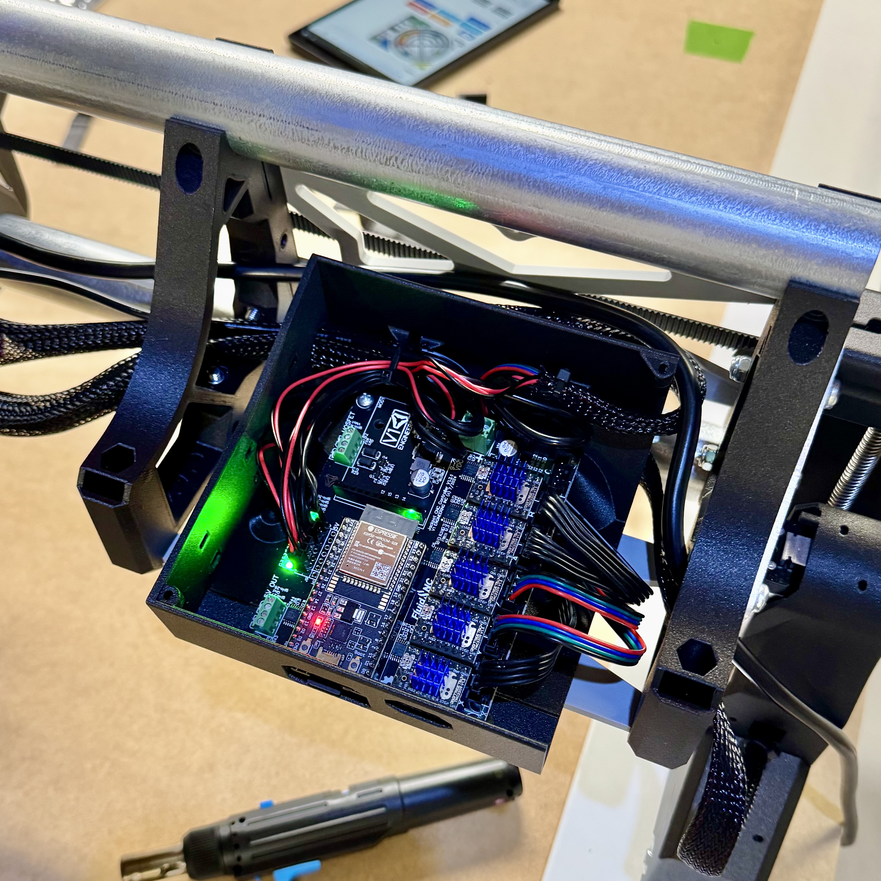
Yeah…I read A LOT and then just kind of went for it. Having the pre-flashed Jackpot board from V1 saved me so much time. Was almost plug and play.
Still need to figure out an accurate way to measure corner to corner to adjust for squareness before running the test crown.
Also need to eventually figure out how to command a probe to square off the Z axis. The terminal commands are different than the Klipper/3D printer commands I’m used to
This is actually super helpful because the docs mentioned a probe tab and I was scratching my head trying to find it so thanks! I’ll try it out when I get home
I believe the z sub screw was left over from beta and last minute ditched. It’s not needed. There are a handful of little Easter eggs that are in the files like those holes. They are for 1 in a million builds. Like the spaces for y endstops on the front wheels, the second endstop position on the core, or the holes you circled.
You could use Jamie’s tp generator G-Code Test Pattern Generator
or simply send the router to x=600mm and Y=800mm and measure the diagonal which should be 1000mm
Congrats for your niuce work
Measuring diagonally across long distances can be difficult with only one person. You can use a beam trammel to help simplify the alignment of the two points with your measuring device. If you’re unfamiliar with what a beam travel is do a Google search for images of beam trammel. It can be as simple as a 1"x2" with a nail sticking out at one end filed to a sharp point and just making marks on the other end. For your size table 56 3/8" in Span will get you close enough to measure the differences.
If you don’t have an extra pair of hands, use some painters tape to fix your measuring tape and do it yourself, it was some kind of tedious but thats the way i do it with my own machines (4*8’)