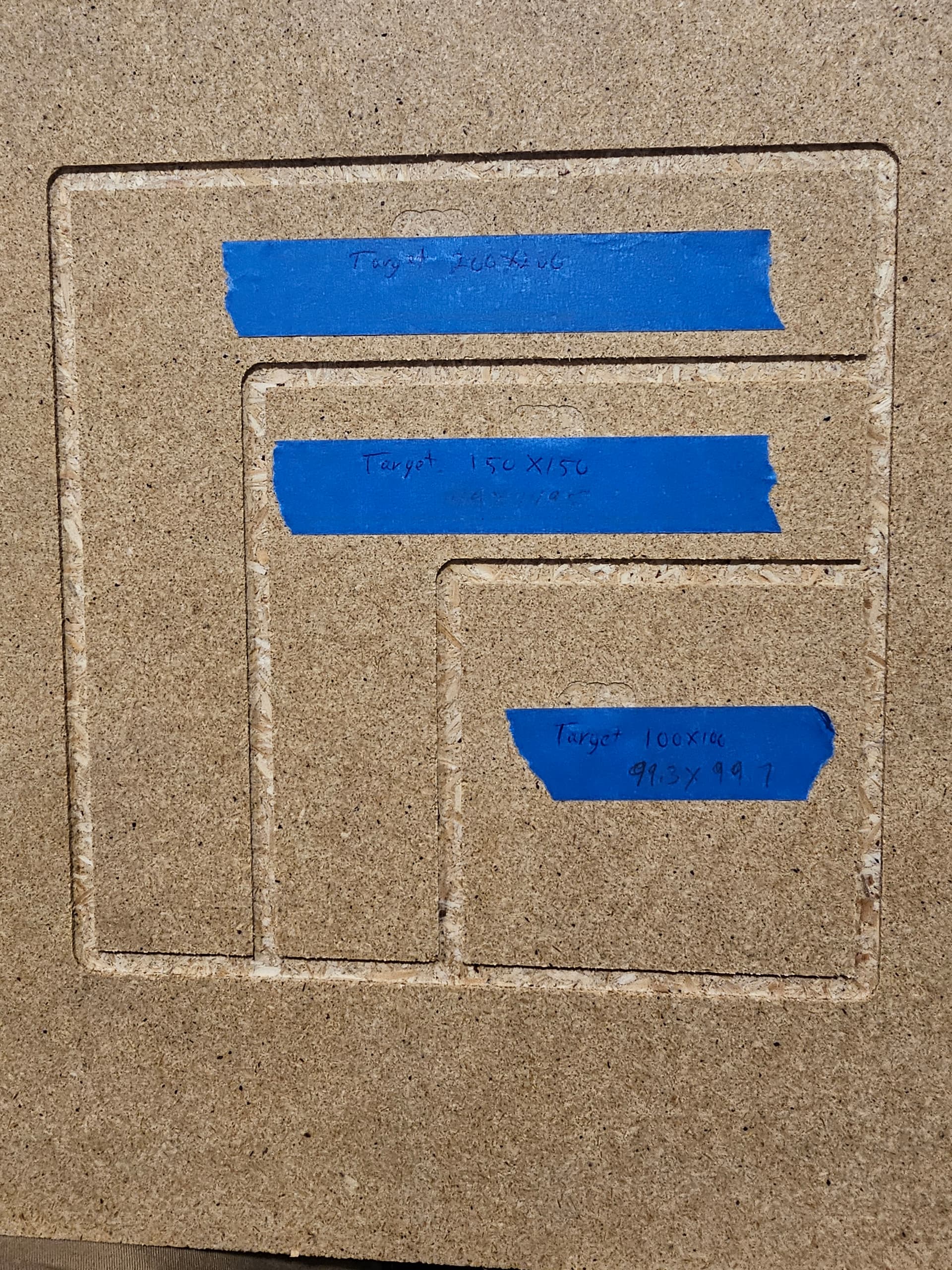
Howdy, im in final stages of tuning now before i really start to work the machine. I cut some calibration squares and im a little short. 100x100 cut to 99.3x99.7, 150x150 cut to 149x149.5 and i found out my little calipers don’t go to 200…
I’m testing on scrap mdf so a little variation between squares isn’t surprising, but is there a quick formula so i can tweak the settings a bit?
So there are 2 places where the cut size can be off.
One is the tool diameter. Even though the tool may be quite precise, how it jnterscts with the material can lead to variations. I find that almost all of my 1/8" mills cut almost exactly 3mm kerf instead of 3.18mm. When this is wrong, you tend to get amounts that are off by the same amount regardless of the intended size.
The second is steps/mm. A proper GT2 belt should have exactly 2mm spacing for the teeth, and with 16T pulleys and 1.8° motors at 16× microsteps should have exactly 100 microsteps/mm, but some variation may happen because of tension. My experience is too much tension (stretch) is normally where this goes wrong. Not enough tension seems to lead to slop in the movement, and you get some backlash type errors. I would check belt tension for the errors you are seeing.
Thanks, tool diameter should be correct. I found my 1/4 endmills were also not quite a quarter. They were/are 6.1 instead of 6.35 and adjusted them a couple days ago. I’m hitting my tools with the micrometer now instead of just punching in the ‘diameter’.
I didn’t think I had too much tension on the belts, but it’s hard to judge. We need a cheap tool I’ll go through them and see if I can loosen a bit and run them again.
One of the community members at the local makerspace was the long-standing maintainer of the shopbot. He swore that the valid test wasn’t measuring the tool (which gets you a starting point), but rather measuring the slot that a given tool cuts in a specific type of work piece.
He always got better results than I did (I never wanted to believe his method because it’s a lot of work and varies with each material). But then again, I’m neither a machinist nor a woodworker, just a hobbyist.
Too much tension would invoke stretch, and you’d get parts too large. Too small isn’t too much tension, but it might be not enough. That tends to introduce backlash instead.
Put a caliper along the belt. 100mm should go from the center of one tooth to the center of another (50 teeth away), or at least the same point in the tooth/valley structure. 0.5mm difference at 100mm should be possible to see.
Edit: the pulleys will be exactly 16 tooth though, and the motor will be exactly 200 full steps /revolution, so any error in travel will either be belt stretch/shrink or backlash/slop in belt tension.
Yep, loosened the belts a whole bunch and no change.
Interestingly, i did measure the actual groove and it does indeed cut slightly wider than the bit actually is. So i reset the bit in the software again. I dont know how that works so I’m chalking it up to magic.