Finding the ideal LR setup for large scale + CO2 laser

Hi guys!

Let me introduce myself first :wink:

My name is Niko, I’m from Berlin, Germany.

I’m a tinkerer as most of you are here I guess, interested in the whole making / hacking thing. I have an architects degree but mainly working in 3D, running my own office / little workshop. I have several things around, 3D printer, vinyl cutter, large format printer and lots of tools. I’m not a programmer but I like code, I’m not an electrical engineer but I wire things together. I’m soon starting my 3rd van build (as a tree just crashed my 2nd) and I will use this opportunity to (hopefully) fulfill a long dreamed dream: a CNC.

I’m planning to do most of the cutting for the van with a CNC as it hopefully fits nice, looks better and is reproducable. Kind of a maker van thing.

Therefor I would like to go big.

I EVER wanted to have a CNC, since at least 15 years, but all the commercial solutions were too big, too expensive and too limited. And just too much over the top for my needs.

I for sure checked the Maslow CNC, cool approach and a small footprint in the shop, but not ideal.

LR seems the way to go and I already dug deep into all the information and forum threads here. I try to keep it as short and clear as possible, looking forward to your opinions on how to mod/opt the build.

  • 1. Cutting large sheets of 3000x1500mm.

I’d like to use the sheets without precutting, big parts mainly for wall covering (4mm birch, poplar…) and smaller parts for furniture / cabinets (6mm to 15mm max). Well, maybe some roomscale things too…

// That size is an issue, I know, I read the mods of a second level of tubes to add rigidity. Are there any mods about linear rails to increase rigidity? Would that make sense? Or wont this size not too much be an issue?

  • 2. Noise level.

The office / workshop is a commercial place (not private) within the city. But its in an old building with mainly residental use and no good sound insulation. I would like to keep the emmision low as possible.

// Whats the main noise factor - the spindle, the cutting or the hoover? Would it make sense to go for a water cooled spindle? Probably I’d have to go for an extra housing?

  • 3. Well, in that sense, what about… laser?

I’d like to add a CO2 laser to cut (up to 6mm) and quicker engrave cuts. Would be quieter (even though a hoover is still needed…), more versatile and the cut width is small, giving other opportunities for snug fit designs.

// Yes, I know, laser… I know its dangerous (and its even more dangerous as I’m not yet very experienced with this, I’m aware) and a laser safe housing of that size is not the easiest task. Caution and extra protection is mandatory. And I know the LR setup is not optimized for that, mainly in terms of traveling speed. But it would be SO cool…! Would have look into fast NEMAs then I guess.

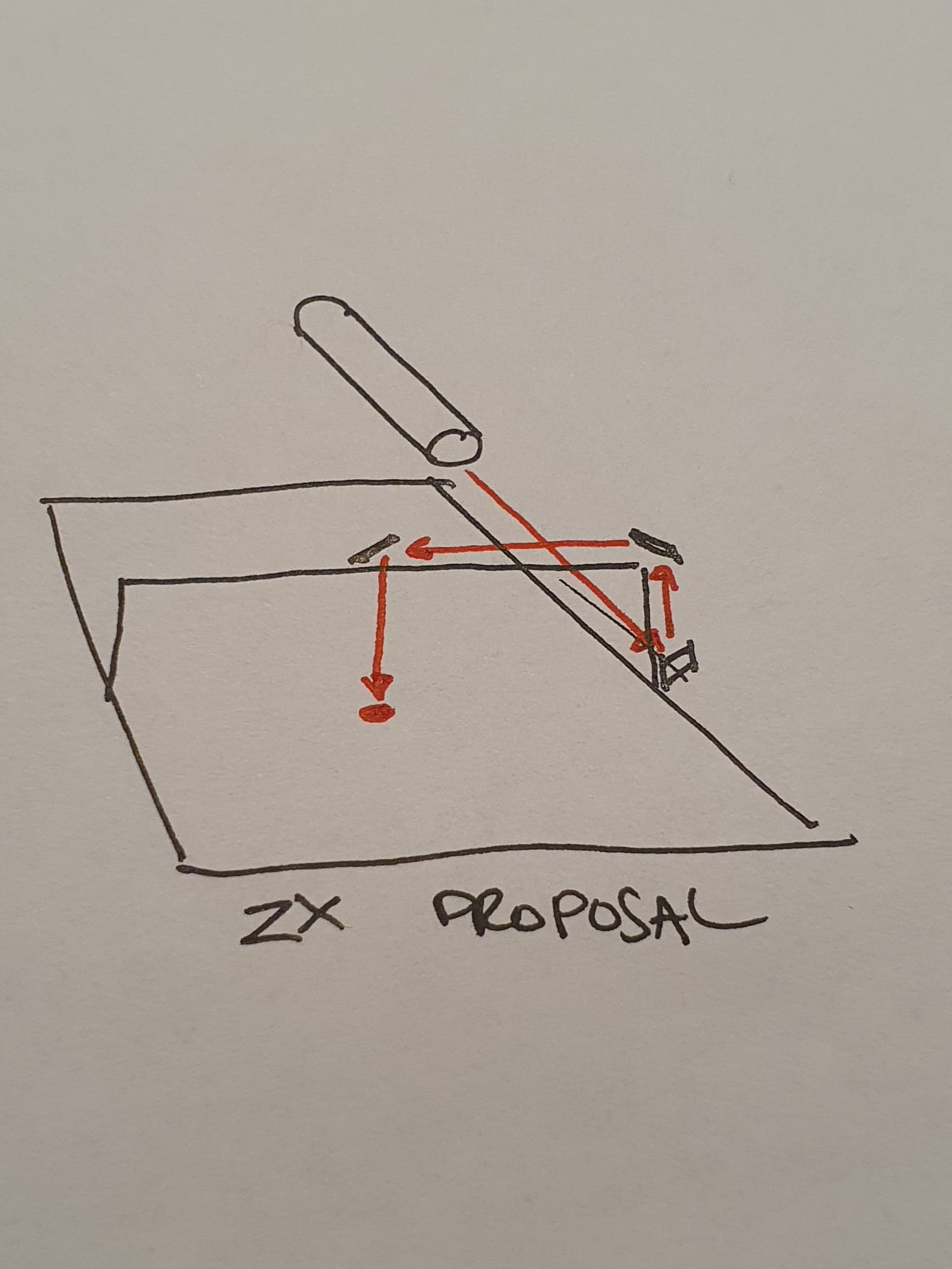
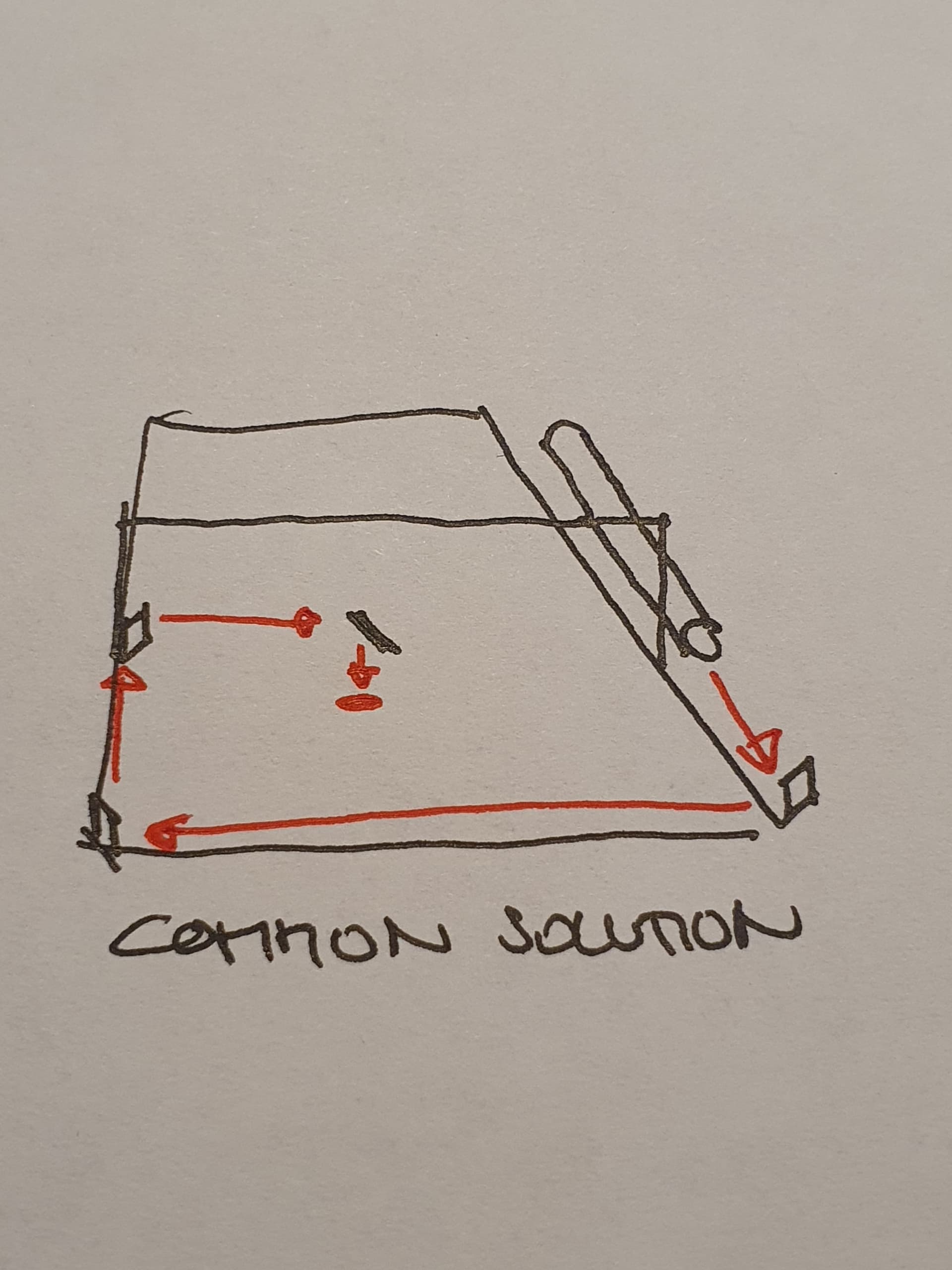
Main question about the laser thing - any chance to get a milling CNC bundle up with a CO2 laser? Maybe keep mirrors in place, recalibrate them when necessary and take out the milling spindle when the laser is working to keep the weight low and the motors quick?

    1. Shop space.

The whole thing wont run always, for many reasons. It would be ideal to make it a portable / store away version. Saw Micheal’s great portable version and its low footprint when stored. This is not the primary goal to bother you with, but might be considered (a little bit) now to be executed later. Maybe cut some parts with the fixed version and rebuild it into a portable one later.

I hope I didnt throw too many questions at you since we didnt have a beer together yet :slight_smile: and I dont get too many “Thats impossible!” back :smiley:

Cheers, Niko

1 Like

If your need is only to cut up to 6mm plywood, you might want to have a look at Neje A60460 double diode laser.
Sure it will not permit to cut fast, around 100mm/min at 100% for 6mm birch plywood in one pass and better to use 80% of power with 2 pass for long job, but with an air assist it will do the job.

You might sometimes have few point/zone not completly cut because of cavity filled with glue or sliced wood knot within your plywood but this is more problematic for small and detailed jobs like ornaments.
For huge cut as you plans i don’t think it could be a hudge matter, when it happens it’s only a few mm at the back of the stock.

You will need some spacer between your spoilboad and your stock to maximise cutting, not honeycomb off course but maybe punk rivet cones like this https://www.amazon.fr/Rivets-Forme-Balle-Accessoire-vêtement/dp/B00B0TMU8A (cheap ones from aliexpress).

1 Like

Requirements 1&4 are in serious contention. It is just very hard to make something that big and have it not take up that much room.

The 3000mm isn’t so bad, but the 1500mm is a bit large. 1200mm is fine though, and if you sacrifice a little speed, 1500 is probably fine. The big factors are sag and chatter in the middle.

The other consideration is that you could easily fit 1500mm sheets in a machine that can’t cut them. If you are not cutting to the edges of a 1500mm board, you should make it smaller.

The noisiest parts on my build are the vac and the actual but chewing wood. The router is right up there, but some heavy water cooled thing is not going to fix the fact that the bit will make noise. It is comparable to my other neighbors using a router or power saw to do construction projects (just maybe not as continuous). My planer is just as loud though, and I’ve used that for an hour, easily.

I second the opinion to use a big diode laser. They are not as dangerous or as fickle as the CO2. There are still a lot of people that say you shouldn’t do any lasering without a complete enclosure. So be sure you are thinking about eye protection and ventilation (and if you plan on opening the garage door, that makes eye protection harder for neighbors and animals). That said, I just started playing with that neje Laser and I use my vac to blow the air under the garage door (open 10cm or so). I keep the kids and spouse out of the garage and wear personal eye and lung protection.

What you may consider doing is making a smaller machine, like 1200x900, figuring out what works for you, and saving the space. Then reuse the parts to go as big as you’re comfortable. You will quickly become an expert and be able to answer these questions, and decide where to compromise, yourself.

2 Likes

Please don’t take any of the following as a “you shouldn’t do that.” This is your build, so you know best what you need out of it.

  1. Large sheets. My converter says 3000 mm is equal to 118 inches, so round it up to 10 feet in my native US units. While this is a bit bigger than “full sheet” size in the US, (which is 4 feet by 8 feet), I don’t think it is an unprecedented length. As long as the table supports the work and the Y axis runs true, I don’t see why it wouldn’t work. I’d plan to include some sort of side guide for the Y axis wheels right from the start.
    EDIT - Trust @jeffeb3 on size and sag recommendations!

  2. As far as noise is concerned, the sound of my electric (DW660) spindle pales in comparison to the sound of the bit tearing through wood. I’ve got a dust collector which, while loud, is lower frequency than a screaming shop vac (which is what I’m interpreting “hoover” in your post to mean). An enclosure could go a long way to helping to keep the noise of the tool from annoying your neighbors. On a big build like you’re proposing, the enclosure will be big, and could get expensive fast. I’d consider something like padded “moving” blankets on movable frames around the machine, perhaps hung from steel cables, as a way to help absorb sound around the machine. Over the machine will be more challenging, depending on the structure of your shop.

  3. CO2 Laser - There’s a couple of examples of folks fitting glass CO2 laser tubes on their MPCNC’s here in the forums - a search should let you get up to speed with their progress and experience. For me, the safety risks far outweigh the uses I’d be able to put such a machine to. You’d need a serious enclosure - not the blankets I proposed above - both to protect from stray laser reflections and to allow for the collection/extraction of cutting fumes. That’s going to big a big volume to ventilate, and the fumes can range from slightly unpleasant (I lased some apple wood in my engraver once, nice campfire effect) to potentially lethal (Don’t even think about cutting PVC - you get chlorine gas). Most CO2 tubes also need active cooling. My main point is that there’s a lot more to think of and engineer for lasing than just getting that light to come on, and go where you want it (and not where you don’t).

  4. Shop Space - To a certain extent, the LowRider is a shop table with belts down the sides and a rolling gantry. These can be removed from the table to allow it to fill multiple roles in your shop, as long as you have somewhere safe to store the gantry (which could be a shelf under the table). Alternatively you can tilt up the table to reduce the storage footprint, or have a modular table you can easily disassemble for storage. Here again there are examples of each of these approaches here on the forums. Search them out, and feel free to contact the posters and learn from their experiences. Ask them what they’d do different if they were starting from scratch. I know I always have a couple of “wish I’d thought of that before now” moments in all my builds.

Best of luck with your shop, your van, and your MPCNC journey!

1 Like

If noise is a major concern and you’re only cutting 2d, then a laser could make sense. I can say even with my little 40W diode laser (more like 5W output), cutting just 3mm ply at a measly 3mm/sec produces plenty of smoke to choke on without a rather noisy evacuation system (in my case a 24" powerful fan that blows through the garage roof). OTOH, if you ever need to cut 3d, then well you need a router and all the bit noise that will bring. I don’t think a rig that is suited to co2 would do well with a router and visa versa, just because the layout of the tubes and mirrors etc it’s not like swapping a router out for a diode laser on a single machine. If you just cut 6mm and can do it slowly, maybe a doide would reduce the noise requirements.

2 Likes

Guys, big thanks to you for taking your time, for your advice and opinions. :+1:

I did not know there were diode lasers capable of cutting those sheets, and 6mm would totally be fine. I just looked up the proposed NEJE 40W diode laser and am pretty blown away. Feels like future. ^^

This would definitely be the better solution compared to a CO2 system, not at least safety wise. Probably a good compromise between noise as well, and nice design options too.

Yes, by hoover I meant vac :wink: and yes, I read quite often that this can be the main noise emitter. I’d probably swap the normal shop one for a newer, quieter one or try to install some damped “tube-ventilator”. Guess if its big enough it should be possible to keep the noise low. The fumes can be routed outside through the window.

I did read those various informations about toxic fumes, mainly PVC and chlorine gas. Good that I did, you never know. Actually saw some Youtube videos of guys lasering all kinds of stuff, seems like they did not read that first… There are good informations on that on the makermade (Maslow CNC) site as they are offering a laser upgrade kit too.

For CNC milling it probably does not matter as all tools are loud. I have to consider some other damping then but dont need to put hoses through to shop to the window. I was thinking of damping blankets as well (eg for building construction there are damping textiles) but t.b.h. I dont know if this will be sufficient.

But I will work through this when I get there, the decision has been taken.

Right now I have a multi-use / meeting table of 1500x1500mm plus plenty of space at least in one direction. I might just extend that and park the LR on one side, the table can then still remain multi-useable.

Would you advise to keep the parts from the list as is? I dont really know if I need more torque or speed or spindle power for my main purpose. Probably not cutting metal and probably with that diode laser I will have to go slower than quicker. Do you think the original design (one level only on the x / short axis) should do it or should I research the modded two level version?

Thanks again, as well for that warm welcome.

Excited to get started!

The double decker is interesting. There seem to have been some success with it. But I am not sure the “juice is worth the squeeze” (as they say). There are also mods for nema23s, which I think are too much, considering the strength of modern nema17s.

The one tough decision is the thickness of the tubing. The outside diameter has to be 25mm or 25.4mm. A thicker skin would make it more rigid, but it would also mean more mass (to move and to sag). The common sizes in north america are 0.065" thick, or 0.120" thick. There are probably similar choices in Germany.

I’m not a mechanical engineer, so I’m not sure how best to advise you on that. Common sense says the sag would be worse with bigger tubing, but thicker tubing is also more rigid.

The trouble with sag and a router is that if you have 10mm of sag in the middle, you would have to cut 16mm from the top of 6mm material to cut all the way through, on the entire 1500mm span. IDK if 10mm is reasonable. I do remember someone early on making a very long LR, and they used mesh leveling and a probe to compensate for sag in the firmware. That was pretty cool, but you’d have some stuff to figure out, for sure.

If you’re primarily thinking of laser, there will be zero drag with a laser, and the laser diode is very light. Sag is also not such a big deal (the focus depth is usable at a large range). So I would go with the thinner tubing (which is what Ryan recommends for the 1200mm span Low Riders). I am very confident 0.065" (or close, in Germany) would work well for 1200mm with a router or laser.

But there is a good chance that the thicker tubing would work better (but be slower) for a 1500mm working area. I am sure someone with some mech-e experience would be able to guess, but I would want to see it measured before I would say either way for sure.

1 Like

I made a rough calculation on this website Balkenrechner: Lagerreaktionen, Biegemoment, Spannungen - Strommer - its german, but math is universal :wink:

Might not fit 100% but selecting a similar sized tube and material (steel matches stainless steel I assume) and adding the numbers for distance, use case and weight should give some direction.

I’d have to double check it with the later router and fittings (right term?) for the correct weight. And not to forget to divide it by two as there are two rails in the standard configuration.

If I’m not mistaken an did something majorly wrong…

In the case above its 1kg (=2kg on two rails) and its only 0.3mm sag. Pretty far from your estimation - which makes me feel I AM wrong :blush:

I saw approaches of filling the tubes with epoxy to add rigidity, but I guess if necessary I’d go for thicker material instead.


That estimation was pulled from thin air, and now I see it is a bit scary. I measured my table with about a 1200mm span and I came up with high and low spots within 2mm. They aren’t aligned with the sag of the tubing at all, so it is very possible I am being overly dramatic.

The router is about 5lbs, or about 2.5kg, I think. The plate, the other stuff is maybe another kg. Does this account for the tubing weight itself? Because that would be the difference.

Don’t get me started on epoxy. I do not think it is worth it :slight_smile:

I’m not starting that epoxy topic, dont worry :wink:

Based on that calculator, if we estimate a weight of 1kg/m for the tubes it gives a deflection of 0.05mm. Something I would kind of expect as well as a round, hollow tube is so stirdy that you wouldnt see any bending on 1,5m. Because its own weight is an equal load, not a point load at the very center and the ends are fixed.

Guess it should be fine then.

For the laser this should work anyways but I’d consider leaving both tools attached and maybe work on the same cut as well. T.b.h. I dont know how much Z tolerance is acceptable, both milling and laser.

If the axis is long it might not only be the static force but during movement those number could change a lot. Eg cutting through wood in a high speed could temporarily bend the tubes as well…

Anyways, I guess its more or less crucial to get the bed flat. As you might have a ±2mm wobble in yours :grin:

1 Like

The equations for prismatic beam deformation are pretty reliable and accurate as long as the initial conditions are done properly. IMHO, for all of the MPCNC machines (LR included), the ends should be considered as pivots, not cantilevers. There’s just not enough plastic beef in those areas to serve as a cantilever. As you’ll notice, thicker tubing ALWAYS deflects less. I studied AE where everything has to be as light as possible hence all the fancy thin shell buckling calcs… but a solid tube was always stronger for a given diameter. After working in manufacturing design, I realized just how over the top some of my AE based thoughts were when it comes to things like cnc machines… if your frame can hold a whale, make it a whale… not like it has to fly through the air. You don’t want to see what an AE designed cnc looks like, lol.

[edit: I’d consider the CNC head as a point load for this. There is space between the bearing blocks, but not much for a big machine. 90% of deflection loads will be from the bit pulling itself around, and the distributed load of pipe weight can be ignored WRT bit loads. I mean maybe you could model it as 2 point loads, but that seems just pedantic when a single point will get you within a few %.

3 Likes

That’s great.

FWIW, a 1500mm work area is a bit bigger. More like 1800mm.

2 Likes

Yes, the router itself definitely can be considered a point load. The deflection of the tube’s own weight would be an equal load but can be ignored (in comparison to the router weight).

Sagging because of the static vertical point force is measurable but maybe not a problem (or better: within tolerance). If a force of 2,5kg is in motion then acceleration / speed is another thing. Or the force a milling bit, pushing into wood, will transfer to the router, then to the rails. If rails then are long and/or bending this might be sth.

But as long as it doesnt matter in the end, its mainly thoughts and theory. We’re not opting for a flexible CNC made from carbon fibre :smiley:

1 Like

True!

I built a full sheet LR2 recently. Due to lack of space, the above is the approach I went with. When not in use, I remove the gantry (and the belts) and hang the whole assembly on some wall brackets. The bed is a torsion box design made of furring strips and a 1/4" melamine sheet. As such, it is pretty light in weight and I can stand the table against the wall. Along with the spoil board and an MDF sheet, the table does not use more than 6" of floor space. Assembly is a bit time consuming (~ 30-45 min). So, do keep that overhead in mind. I also have some handy cncjs macros that I run every time after assembly to ensure that the motion along X, Y and Z axes is smooth before starting a job. I am doing CNC mostly as a hobby. So, I don’t plan to go through the above motions too frequently. It quickly becomes a chore if one has to do it frequently.

1 Like

I’ve been thinking about how a person could mount a CO2 laser to a LowRider with any degree of safety…

Most CO2 laser tubes are fixed-place mounts. The beam is reflected around so that it bounces parallel to one rail, then a moving mirror reflects parallel to the other rail. This is because moving the actual tube itself is somewhere between troublesome and dangerous.

Ok. Idea one. Fix the laser to the table, parallel to the Y rail. On the Y plate, a mirror reflects the beam to vertical alongside the Z axis, and another mirror on the XZ carriage reflects it back to horizontal. Finally a laser head on the carriage reflects it back downward towards the cutting lens.

Potential problems: If the Y axis becomes skewed because one of the Y motors gets stuck, now you’ve got a 40W laser beam hitting your ceiling somewhere. It probably won’t be hitting the mirror to deflect it along the X axis anymore. However, if the Z axis is a little off level, it should still be OK, so long as the mirror on the Y plate doesn’t move out of the beam. All of the optics will be very difficult to enclose in this setup, and dust is likely to pose a significant problem.

Second idea. Mount the laser tube above the X axis. In its simplest form, this would duplicate the angle piece for the cabling solution on the other side, with the laser sitting inside the “V”. This avoids all of the problems with the Y axis, because that’s no longer any concern at all. Similarly the Z axis is irrelevant. All that matters is that the laser is parallel to the X rails. A mirror deflects the beam downward, and then back inward, allowing the laser head to move the entire width of the X axis. The advantage here is that this structure can be as rigid as you can make it up to and including welded steel. The laser tube and mirrors can be enclosed to keep most dust out, leaving only the final mirror at the laser head. The downside… We’re moving the laser tube, which we kind of don’t want to do.

Of the two setups, I’d probably opt for the second. While moving the laser tube seems like a bad idea, the fact that it can be securely mounted to the X rails via something like welded struts has a fair amount of value in terms of safety. The idea of stray laser beams hitting random and unpredictable places as is possible with the first scenario seems like a poor compromise, given the choice.

@SupraGuy I guess the moving tube is not the best solution, heavy, fragile, filled with water…

The “normal” setup probably is a tube along the Y axis and the beam is reflected inside the working area.

I don’t know if I got your XZ proposal right, but wouldnt it mean the tube would have to be outside the working area, see sketch?

I guess I would or will go with the NEJE 40W (equals 10W CO2?) laser first. Easier to set up and first testing the boundaries. If neccessary I guess adding some mirrors and a CO2 system would be possible even though more complicated. Maybe not ideal to start with :smiley:

The safety concearns are important. Maybe it could be possible to build some extra mirror housing, so in case something goes wrong the mirror wont reflect all around but just block the laser (black matte metal eg).

For sure it would be nice (I imagine) to have a powerful laser that cuts quickly. Lets see :wink:

@sparkm I will have to have a deeper look into the setup (how you described it) and how it can be taken apart / reassembled. Maybe its just ok to be able to use the working area for other stuff as well, a table is always needed.


1 Like

Laser tubes require coolant and are glass, so need to be protected from impact. Mirrors are costly, don’t provide perfect reflection (i.e. result in power loss), and can be tricky to align, so most designs work to minimize the number in use.

In my experience, the “common solution” in dedicated laser cutters which use laser tubes (not in LowRiders) is for the tube to be mounted in a protected casing parallel to the gantry outside of the cutting area - about where the words “Common Solution” are in your last sketch, although they’re normally in the rear to make access to the cutting area easier. This eliminates one mirror (along with the related power losses from reflection and complexity of alignment) compared to the sketch.

They also mount the laser tube so that the beam falls higher (by the height of the final focusing mechanism & lenses) than the highest expected Z height, and have the final mirror (that turns the beam “down” toward the work) at a fixed height on the gantry, to eliminate the “up and over” mirrors from the ZX proposal.

This results in 3 mirrors, one right at the end of the tube to send the beam parallel to the Y axis, one at the end of the X gantry to turn it parallel to X, and one in the “head” that turns the beam “downward” toward the work. The head also holds the lenses that concentrate the beam to a cutting intensity.

3 Likes

For the “normal” setup, I’d reduce one mirror, put the tube parallel to the X axis, but yeah. Or add one mirror to the “ZX” picture that you have.

With that setup, like I said, you need to be very careful to always have the gantry square to the table, or else you’re going to miss the top mirror, and shoot your laser into the ceiling. The fact that the LR can deviate from square while unpowered, and returning to square is unenforced makes this potentially dangerous. Anything that causes one or the other Y motor to skip steps could damage your machine, your workspace, or start a fire in a matter of seconds.

One note about CO2 versus diode lasers: The output power of that A40640 laser is 10-15W, but not equivalent to the same power in CO2. This is because the light wavelength is different. The diode laser emits blue light. (450nm wavelength) where a CO2 laser emits about 10.6 μm. (Or 10600nm) This longer wavelength (Infrared) makes the laser useful for things like clear acrylic, which your diode laser cannot cut. It also makes for easier shielding (Clear acrylic will shield you from harmful reflection from a CO2 laser while allowing you to see the cut area)

1 Like

@ttraband Yep, totally correct, along the X axis absolutely makes more sense. Cross the “common solution” please :smiley:

I’m not deep enough in the topic yet (obviously :slight_smile: ), was trying to visualize my thought in reply to Dan’s post before.

@SupraGuy “LR can deviate from square while unpowered, and returning to square is unenforced” ah, didnt know that too. Maybe I have to look for some pro’s & con’s of the build, just to be aware of what to look deeper into and to take care of. Thanks for pointing that out.

I thought the A6040 was 40W (as of the 40 in 6040) but sure, the data sheet states 10W output power. Input 12V/4A. I start putting the pieces together. I’m aware of wavelengths, basically, from high energetic short blue wavelenght to long wave infrared but havent yet made the connection of how this affects various materials in cutting. As all laser are cutting with heat I dont really get how infrared wavelenght can cut transparent material and blue light cant.

Makes sense with the acrylic shield from this point though.

1 Like