Finally building my ZenXY

I’ve been wanting a robotic sand table since I saw say the Sisyphus shortly after it came out. That desire got even stronger back in 2016 when discussion on this forum first started about a v1 version. I forget exactly who/how it started…but I do remember @Ryan coming up with a hardware design and @jeffeb3 starting what became sandify to create patterns for it.

I considered building one a few times…but really did NOT have room for one.

Well, now I have room.

I also have a table with a broken top and a partner who has ok’d me turning it into a zen table:

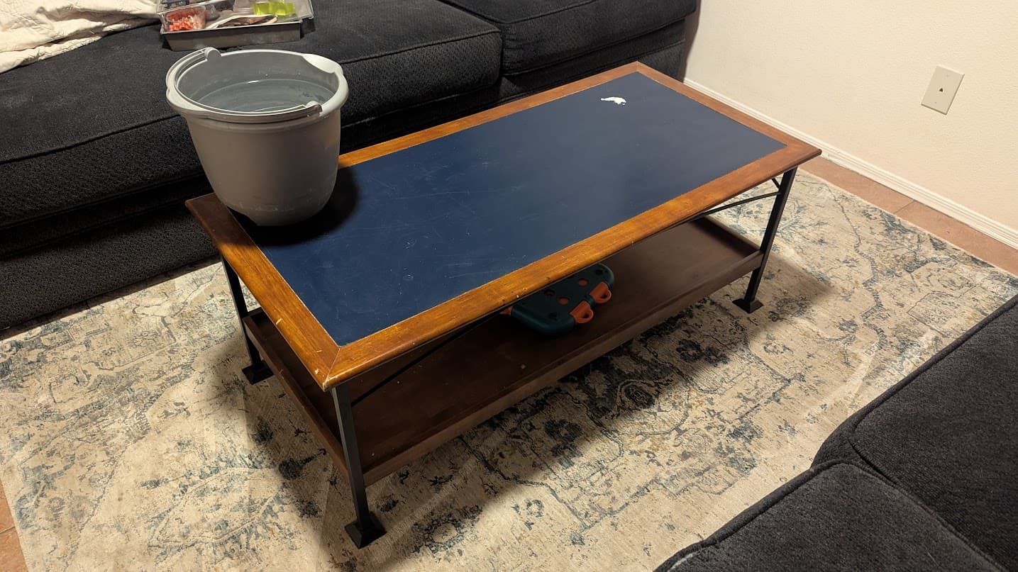
I’m still debating if I want to make a drop-in table that uses the same size glass the table was designed for. Or if I want to just remove the top all together and mount my own top to the legs. But I’m also having a hard time getting my head around drawing space vs. machine size, vs. glass size and how that will work out.

I went to look at Ryan’s Fusion CAD of a table sample…but that link is currently broken. So I’m just going based on the drawing on the calculator page and the calculator.

And…to really get a feel for it I think I’m going to build it as a smaller 20"x20" portable table first…then I can decide how to build it into the actual table.

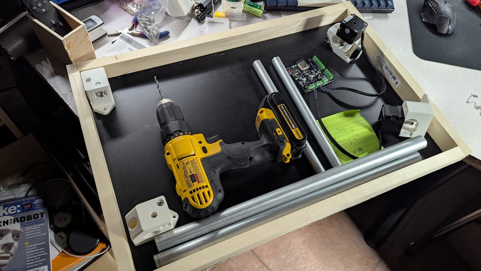
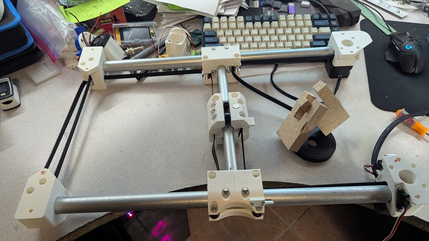
I printed all the parts a week or so ago - though after taking this photo realized I had them positioned a bit wrong:

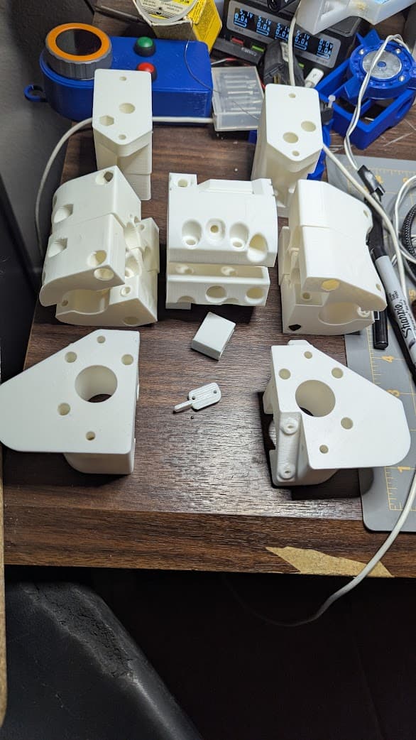
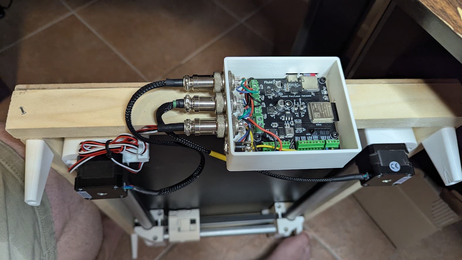
I had some of the parts on hand already - 4 idlers, the 2 pulleys, belt, most of the hardware…and I ordered a FluidNC 2 channel board which I put on my already build eggbot - which I also plan on poaching the motors from:

I ordered the rest of the parts I needed from the v1e store and USPS told me to expect them last Thursday. So I was planning on a nice relaxing weekend of building. Then USPS decided the parts should spend a day sightseeing in the LA area. Then they decided they should spend another day around Phoenix…and they really needed a day of rest after that. So delivery was delayed until today.

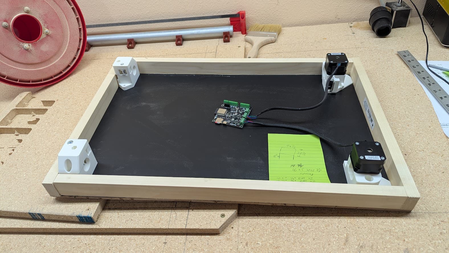
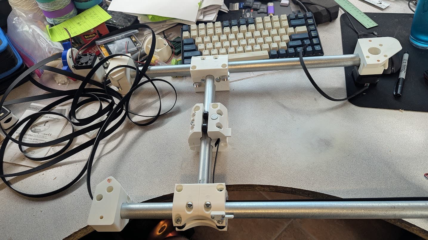
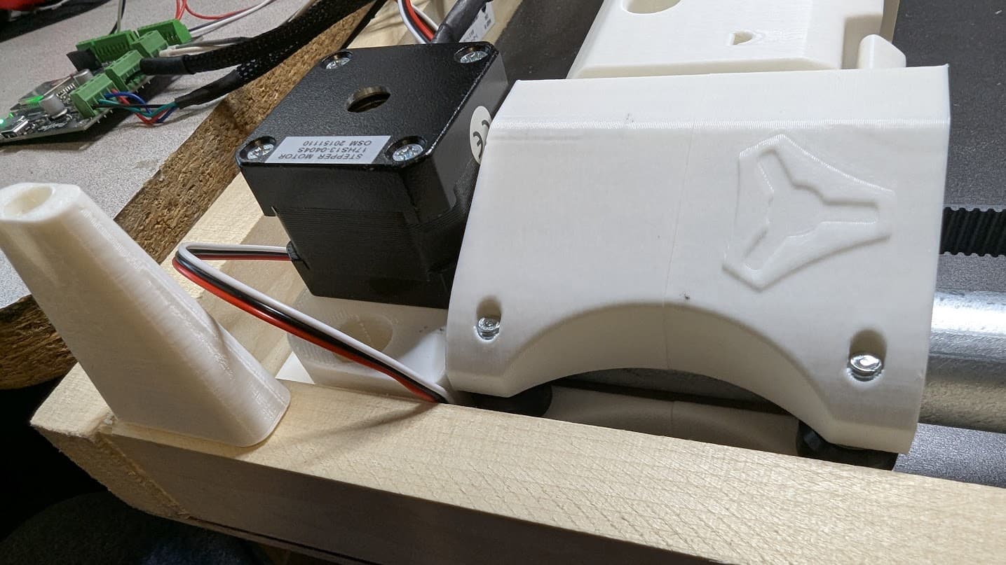
They showed up just as I got home for lunch so between bites of leftovers I was able to assemble the truck:

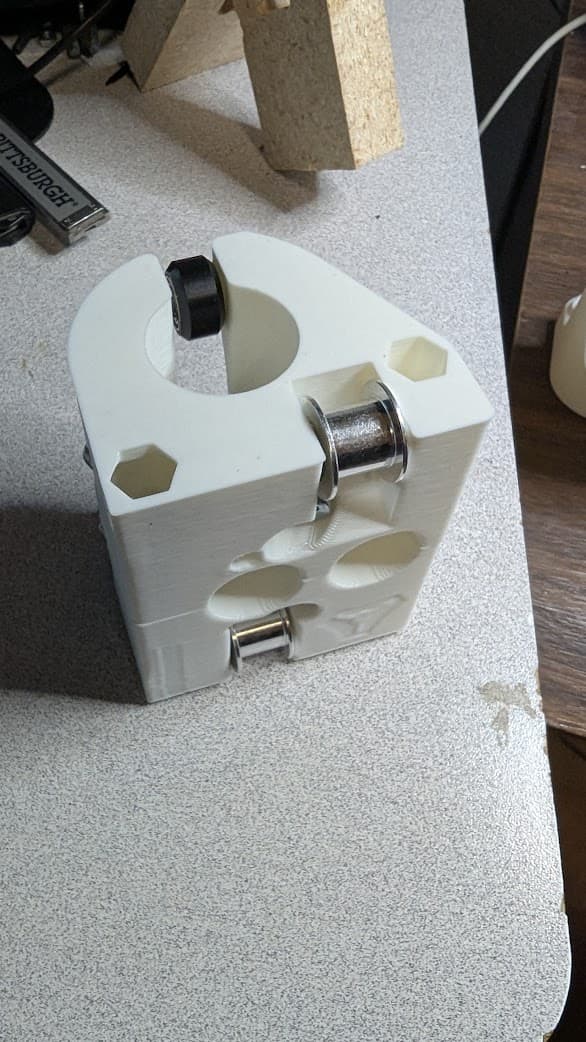
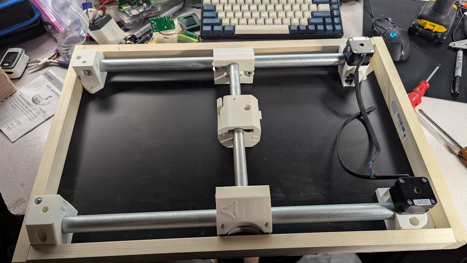
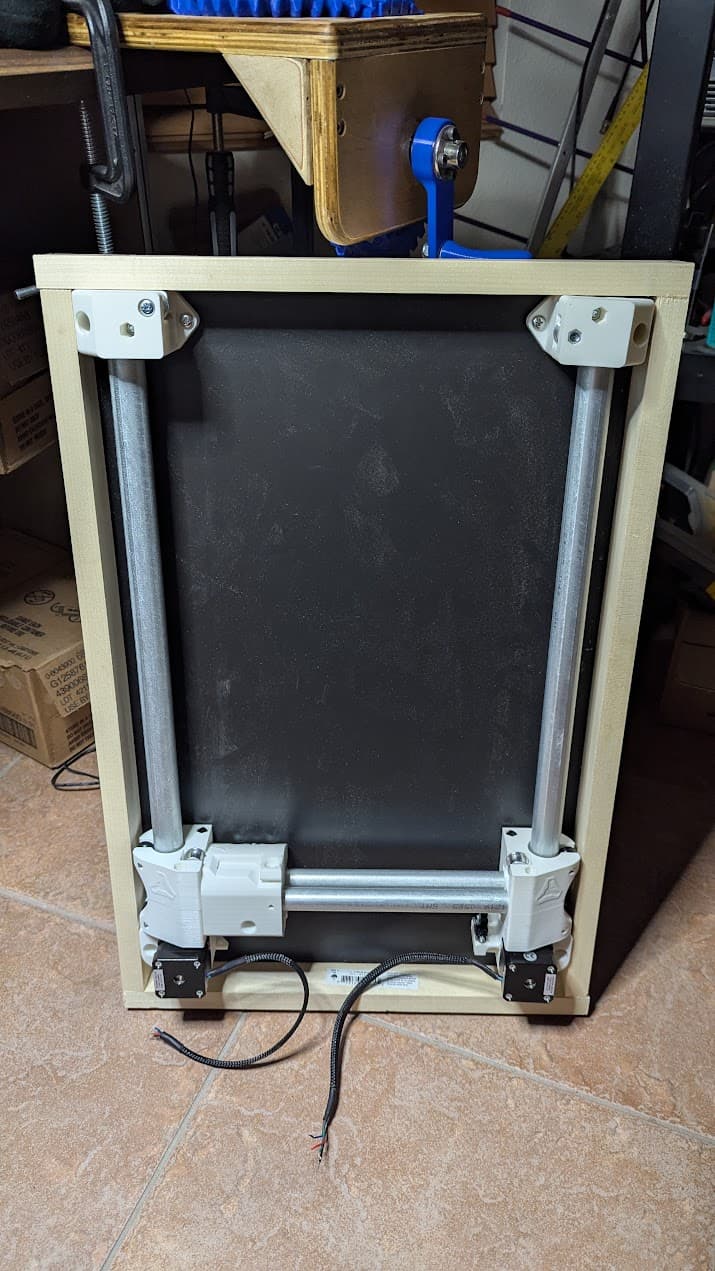
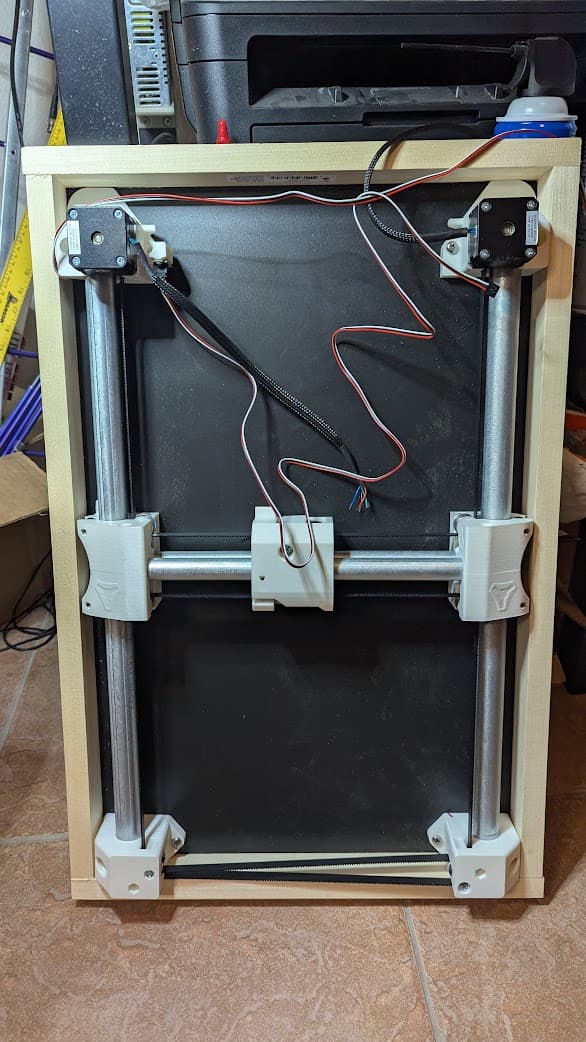
And tonight after dinner I assembled the rest of the parts:

Have to say - I’m just a little disappointed. I was hoping for a bit more of a challenge - I suppose that part is coming when I get to route the belt :grin:

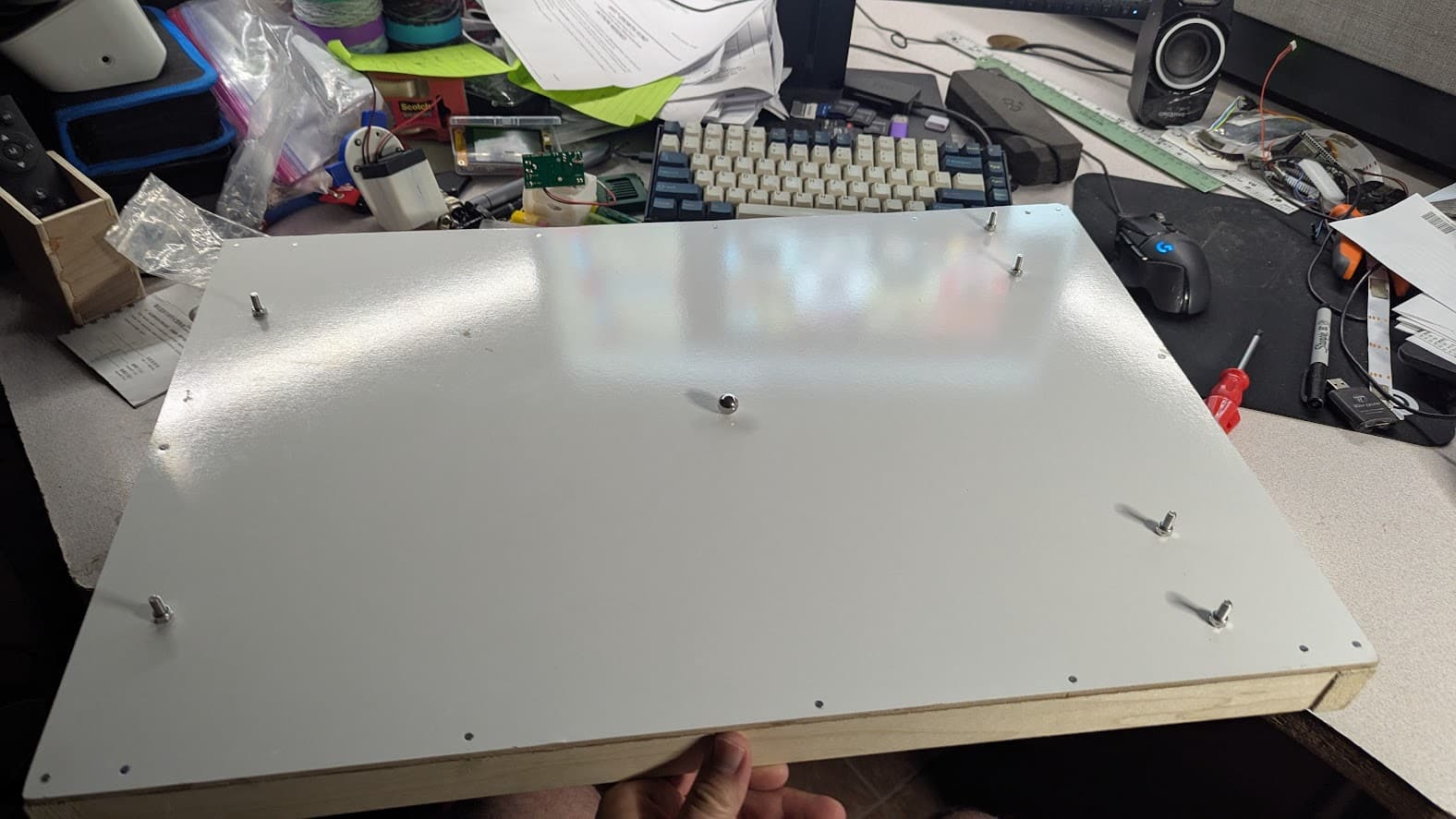
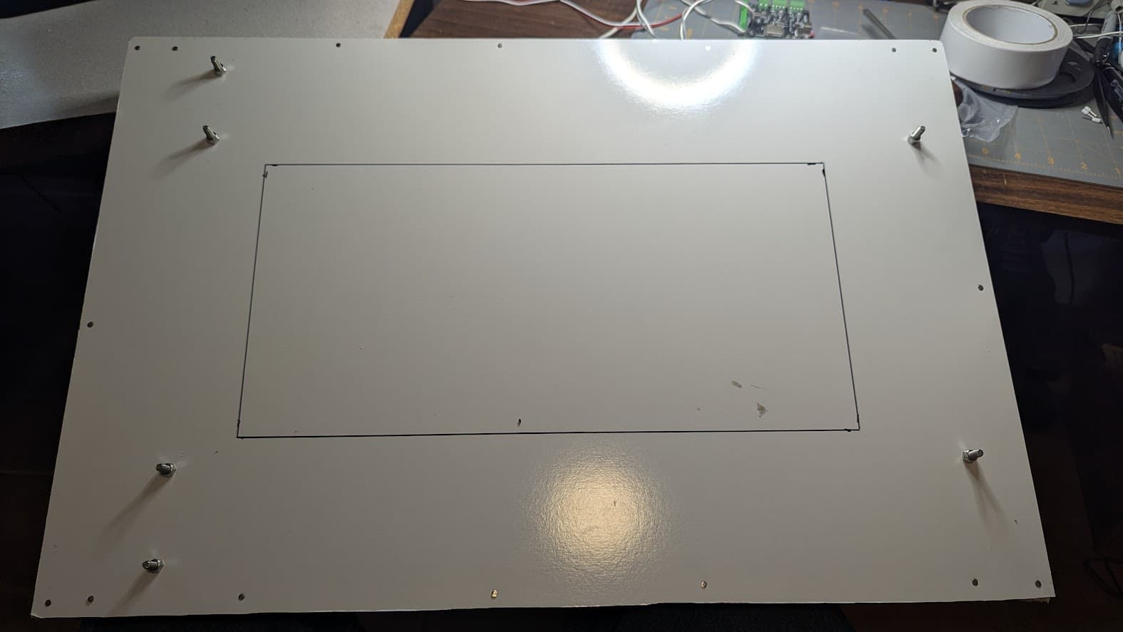
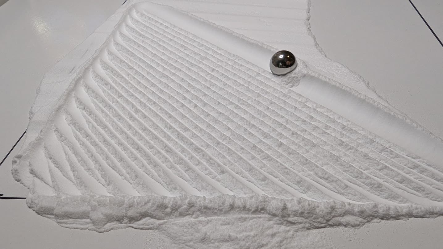
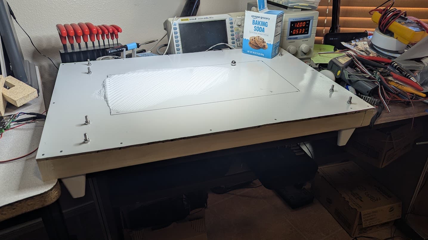
Anyway - it’s almost ready to go…I went out to the garage to see if I had any thing I could do a test assembly on - but all I have right now is 1/2" ply…I tested and the magnet is strong enough to move the ball through that…but not very well and with the extra friction of sand (or baking soda) I doubt it would work very well at all.

So - temporary hold until I can pick up some thinner material to use as a base. Debating if I can get away with hardboard/mdf or if that would be too rough and it really needs to be glass or acrylic.

Anyone who’s already build have any suggestions? For this initial build I’m not looking for a full final solution - just something that will work well enough to give me a feel for the machine and how much space I need to build it into an actual table. So I’d rather not deal with actual glass at this point if I don’t absolutely have to.

I also realized that the motors on my eggbot are much smaller lower torque motors than specified. I already mentioned this in another thread and Ryan confirmed it should be ok - as long as I keep the speeds and accels lower. Which is fine for me - I’m looking for a slow table not a speed demon anyway.

now - back to digging through my garage trying to find something thin enough to use as a temporary base …

10 Likes

Nope, simple. The only real challenge on this one is getting the homing procedure dialed in. The code is up obviously but getting it right on your machine takes a few tries. You really want to use every available mm, and also make sure it homes right every time. So that part is a bit different from the other V1 stuff…I really want to remake the Zen, but I have been saying that for a few years now.

3 Likes

The benefit of glass is it is rigid and flat. You can dial in the magnet to be just below the bottom surface and trust it won’t scrape in the middle. Small spans of hardboard work. I made my first prototype with hardboard and it was about 20"x20". It scraped as the hardboard eventually sagged.

Another very rigid material is Aluminum composite (which is plastic with aluminum skin on either side). I have seen that used in other tables.

For a prototype? Hardboard is fine. It won’t hurt anything. Cut it the full size of your coffee table and then frame up the inside. For the final table? Use glass.

My table is on onshape. I can find the link if you can’t. It is sized well for LEDs.

2 Likes

That’s what I used to design mine and it looks like it will work well. Still have yet to build it though lol.

3 Likes

Found your OnShape design @jeffeb3 - looks great…but…also a bit “more” than I want to do for this first test. Definitely some ideas that I’ll carry over into the finished build though.

After work yesterday I stopped at Home Depot to pickup a sheet of 1/4" MDF planning to use that for the temporary test table since I know it’s only $15 for a quarter sheet and usually the lowest cost sheet good I can find. Well, turns out they had something even cheaper. I got a sheet of 1/4" hardboard with whiteboard on one side and chalkboard on the other for $8. Would probably sag over time…but for this temporary test it should do fine.

I was in a rush so didn’t get many photos - but I cut a 16"x24" chunk of it and added some 1x2 poplar strips to reinforce it since I had it on hand:

It looks warped in the photo but that’s just the wide angle lens - it’s actually very flat across the top. I put the whiteboard side up figuring it seemed smoother. I was tempted to put the chalkboard side up since the dark finish may look better against the white baking soda as the ball leaves a trace…but…decided to just got with the slick white.

Went back inside and used the calculator to get my EMT lengths, then back out to the garage and cut them. One came out a hair long but a few seconds on the belt sander took care of that. And by that point I was dripping in sweat from being in the garage even though it was cooling down outside so…I brought it all back inside to assemble at my desk instead:

I actually picked the 16" dimension because it should just barely fit on my electronics bench that size :smiley:

A few minutes later and I had it test assembled:

Only took me 3 tries to get all the parts in the correct orientation :rofl:

Next I marked and drilled holes to mount it to the temporary top. And realized I’m going to have to deal with the same clearance issue @jeffeb3 had in his build:

Not sure if I’ll want to cut some clearance into the siderail or just solder wires directly…

I also only got one screw each into the cross corners - even my long skinny marker didn’t quite make it deep enough to mark the other hole. I’ll have to deal with that those tonight:

It moves well over the whole range - though it does seem the trigger on the center sometimes gets hung up on it’s endstop…may have to do some fiddling there.

I also find it kind of funny that it looks a lot better from the bottom than from the top:

The top is just boring right now with just a ball…and those screws sticking out from mounting it.

But - all is looking good so far. Tonight I’ll take it back apart and run the belt then wire it up.

Not sure which motor should be X and which should be Y on a corexy setup like this…but I see the fluidnc docs have some tips on figuring it out.

Hopefully tonight I’ll have it moving under it’s own power.

I don’t really plan on making the top very “polished” on this…I may add something to define a perimeter around the baking soda…but really this is just to get a feel for corexy and confirm I can get the controller working. And to help me get a feel for the size of the mechanism vs the size of the working space.

So far my thoughts on the ZenXY design overall:

  • It would be nice if the screws could be oriented so you can loosen/tighten the clamping of the EMT while it’s mounted to a table. Some screws face the table though so right now you have to unmount it to do that.

  • That endstop is really in a tricky location to deal with.

  • It would be great to have an option to mount it from the side instead of the top…build it into a frame basically. If it was attached to the poplar boards and the top was screwed on instead of nailed and glued it would be a lot easier to assemble/work on.

  • The mechanism really is a lot “bulkier” than I expected. (Funny, way back in high school I participated in Science Olympiad and got roped into competing in “metric estimation” which I turned out to be way better at than I expected - got 2nd in state even. So - I’m fairly good at estimating the size of things in real life. But put it on a computer screen in CAD and my sense of dimension goes all crazy and I can’t really get a feel for how big anything is even looking at the actual measurements.) You lose almost 4.5" between the outside edge of the mechanism and the edge of the drawing area - so 9" overall in each dimension.

That last point has me questioning the table I plan on building this into permanently. My existing table is 46.5" x 22.5" but the opening in the middle I wanted to drop something into is only 18.25" x 42.375"

So take 9" off each of those dimensions and I’ll only have a drawing area of 9.25" x 33.375" which is really narrow and long. So replacing the entire top is sounding like a better option (because the way the legs mount currently it isn’t really feasible to mount this outside of the existing opening either.) But even replacing the entire top my drawing area would be 13.5" x 37.5" which is still really long and narrow.

So…I may just build a whole new table that’s more like 24"x38" or something so it’s not quite as long and skinny…I can also design it to match our other table then…

2 Likes

Oddly enough I did actually make that change. The files seem to have gotten lost of forgotten somewhere.

The whole point of a redesign would be to reduce this. I am fairly certain this is not as easy as it seems with these parts. The bummer is most people do not like asymmetry so the largest corner sets the dims. That is the reason the other corners have the space flanges, if you were okay with asymmetry you could buzz those off.

1 Like

Me neither, but a) you don’t see it and b) the LR4 is asymmetrical as well… :sweat_smile: And it seems to do okayish… :yum:

Oh nice…As I was test assembling this last night I was thinking “oh, I bet Ryan planned this so those are all accessible since that’s the kind of thing he does” and was surprised when I realized they weren’t already done that way :smiley:

Yeah…I was thinking last night about ways to reduce the bulk…but nothing obvious was coming to mind. But I’m not sure how much is possible without abandoning EMT as a rail. Eliminating the flanges would help…but just the width of the rails and the plastic to support them seems to be the bulk of the bulk. Going down to 1/2" rails on the outside may help some…but the belts/idlers are also always going to take some space.

Without ditching the 3D printed aspect I don’t see too many ways to reduce the space the mechanism takes up…yeah, a 1/2" or 1" here and there may be possible - but going from 4.5" per side to say 2" just doesn’t seem possible with 3D printed parts.

But…I wonder if using some milled parts might open some options. Keeping the current v2 as a 3D printed version but maybe doing a “less printed” version with more parts machined on a MPCNC or LR4 may be a path to something more compact. I haven’t really thought it through super well yet…right now just focusing on getting this up and running before letting myself start to think about how things could be done differently.

And of course - just want to reiterate that I really hope this comes across as constructive criticism that can help improve things. I love the design and the fact that you’ve shared it with us all and don’t want to come across as complaining. I doubt I’d have ever been able to design something like this from scratch myself so I’m not looking to throw stones here. Just sharing some thoughts in the interest of making a future revision even better!

4 Likes

So over lunch I put the ball on and marked out the extents of where it can travel:

And I was a bit off in my earlier comments. It’s actually 4.25" not 4.5" that the drawing area is inset.

And…1" of that is just because of the wooden frame I put under my board - the actual machine size is only 14.375"x22.5" even though my top board is 16"x24".

I didn’t actually measure the “working area” … but … you can do the math if you want or just use the calculator :smiley:

I drew my lines by just putting the ball on - moving the center to the four corners and marking the edges of the ball then connecting the lines.

After I took the photo I took a few minutes and drilled the 2 missing holes and finished mounting things - though this evening that’s all coming back off so I can run the belt and wire the end stops.

I also noticed there’s almost enough room to mount the controller underneath due to that gap. If I made a few notches in the frame I could probably pull it off. But since this is just a temporary platform I’m probably not going to put in that much effort.

I’m just hoping to get this moving and get some lines in some baking soda - then it all comes apart for the real build. I could add some more layers to this to allow for lights and a real cover that hides the mounting hardware…but…not much point since it’s just a proof of concept and I don’t have the cash to buy another set of steppers, hardware, and controller to keep this one as a portable version to go with the coffee table I have planned.

2 Likes

I was just hoping you could use the dimensions to help guide your build. Especially the LEDs.

2 Likes

Few quick thoughts as I progress tonight.

One of these days I will learn to trust the belt length from the calculators. Today is not that day. Today SHOULD have been that day. I made this a lot harder on myself than it had to be:

But…I got it:

Note - I really wish I knew why github pages never load photos in lightboxes for me. having to open the photos in a new tab to see them larger is really annoying. One of these days I’ll get to the bottom of what it is about my copy of chrome that makes it not like that.

(oh interesting…incognito mode works…but then freezes every chrome window/tab after enlarging a photo. Sigh. May have been a fluke though - worked fine once the browser started responding. So…must be an extension causing problems. Wish I had figured this out an hour or so ago.)

Note for anyone else building until the docs get updated. The belts twist when passing through the 3/4" tubing. Missed that at first and had to redo 3 idlers once I realized my belt was the wrong way around and back tracked to a photo where it happened.

Also - getting that last tensioner on is a bit tricky if the machine is already mounted when you install it since it’s really meant to be installed from the other side. But I wanted the machine mounted to figure out the belt length since I didn’t trust the calculator (just since I didn’t have enough belt on hand to risk make any mistakes cutting it too short.)

The endstop wire just barely fits…but it’s not great…will plan for that better on a “real” build. But it’s mechanically together:

In fact…I’m only at the computer because I was about to figure out my config.yaml. Note - the docs link to a grbl_32 version not fluidnc - but there is a fluidnc config in another v1 repo. But it’s for the older version of the laser board…so I’m double and triple checking everything to make sure the pins are the same…it looks like the endstops opperate in reverse from the sample config from Bart for this board. And I think I remember seeing one or two pins that changed when I looked at it last night.

Oh - also found why my one end stop hangs up sometimes. Sanding down the bottom of the screw on trigger piece gets it to clear. The end stop just sits a hair lower than the trigger is expecting. Should be no big deal since there’s still plenty of trigger to trigger the endstop it looks like.

Ok…back to config.yaml and let’s see if I can get movement tonight!

1 Like

Hey, it moved first try:

Moved backwards…assuming it homes to 0,0…but I swapped one coil on each motor and it moves in the correct directions now.

Endstops don’t seem to trigger…I’ll have to figure those out.

Tried a really quick pattern in sandify and uplaoded it … got an error about no feedrate … set a feedrate and it moves the ball around:

Though…since I don’t have homing working and I didn’t start it in the right spot…it tries to go beyond its bounds quite a bit on this first test.

Baking soda should be here tomorrow…and hopefully I’ll figure out homing and get sandify’s dimensions and starting point sorted out. But for tonight I’m happy and ready to get some rest now :smiley:

6 Likes

Took a quick look at the endstop situation this morning over breakfast.

First issue - the +5v wire to the endstops keeps coming loose from the control board. I’m really not a fan of the style of terminal used on this board…and the really tiny ones used for the inputs/outputs are extra annoying. I can’t use my crimp on ferules on these wires because the wires are too small…and I suspect the terminals are too small for the ferules anyway. Plus I have to get out an extra tiny screwdriver for these tiny things.

But I got it connected and confirmed I’m seeing 5v going to the endstops. The endstops do trigger when I shove something into their path - but they’re only sending 2.25v on the signal pin even though there is 5v on the red wire. Not sure if that’s enough for the board to detect as closed…and not sure why it’s not 5v. Never worked with these endstops before and there aren’t many details in the store. So I may have to do some digging.

Also when I did try a homing cycle it was painfully slow. So I’ll have to adjust that. I could barely tell it was even moving it was homing to slowly.

But - both my daughter and GF are more impressed by it than they were the LR4 and I don’t even have sand on it yet. So that’s a good sign. And it is absolutely silent as long as it doesn’t try to go off the edge and loose steps. Oh yeah, I also put a ruler against the center and did some 10mm moves confirming that it does indeed move exactly 10mm when ordered to. So setup is mostly correct!

Did a bit of investigation over lunch on the end stops.

Running $Message/Level=Debug so I can see when they trigger I confirmed that both trigger. I’m guessing the lack of trigger yesterday was from that +5v wire that kept coming loose. I see they also have a LED on them to indicate triggered status and confirmed sticking a small bit of plastic into them the LED comes on and the console shows a message indicating the triggered.

Tried homing Y…but it just crashed and never triggered - so it seems the trigger isn’t engaging with the endstop properly. That’s…going to be tricky to deal with since it’s so hidden away with the machine mounted up like this…fun.

Tried Homing X after Y was in home…and it triggers as expected…but the wires can easily get in the way. Now I see why @vicious1 warned that the endstops can be tricky.

X should be fairly easy to deal with - just take off the end stop - remove the connector and solder the wires directly so I can have more clearance around them.

Y…that’s going to take some thinking. I can’t even see what’s going on with it when it should be triggering. I could just drill a hole in the top to get access…but even though this is a temporary setup that’s a little too much for my taste.

I could take another sheet of the material I used for the top and mount the machine there with more of an opening cut out…or I could try to jig up some way to support the machine without it being mounted to a full sheet.

good thing I’ve got all afternoon to let this back burner in my head :smiley:

1 Like

Still haven’t sorted out Y homing…

Just really not sure how to tell why it’s not triggering since it’s completely inaccessable:

But…my baking soda arrived so I couldn’t resist giving it a go:

That first test pattern revealed a few issues with it hitting limits…so I did another with a spiral wipe after shrinking the size down a few mm based on where the lines in the “sand” actually stopped. So I’m down to 175x380mm and it still “clicks” when it hits X0…

But part of that may be due to the homing issues. The machine is slightly out of square…I suspect it’s basically one tooth off on one motor. When it’s at 0x0 the gantry is flat against the motor mounts on the end stop side - but about 1mm maybe 2mm off the mounts on the other side.

I know the instructions reference using the spot on the center where the belt passes through to help square the machine…but no details are given. Anyone have any tips? I mean…it doesn’t have to be perfect since it’s just art…but I suspect that’s why I’m getting this click that I’d like to eliminate. I suppose I could just try adding a bit more pulloff on x so it doesn’t go quite as far in that direction…Now that I write it out and watch that makes sense…I think it’s the center hitting an idler in the truck at “0” that’s making the click. Adding a bit more pulloff on X so it clears that is probably the solution.

So it works…I can’t fully home yet but I can just manually home and zero the machine until I work that out. I might try modifying the trigger slightly to see if that helps.

Oh, and apparently I didn’t mesasure very well…16" doesn’t quite fit on this table as well as I thought it would :frowning:

oops :rofl:

On the upside…running it off my bench supply I see the current is never going over .7amps at 12v. And I have a 2a 12v wallwart just sitting here I could use to power it so I don’t have to stay on the bench. It’s just handy since that’s also next to my computer :smiley:

5 Likes

So upping the X pulloff to 3mm instead of 1mm solved the slight clicking sound.

Though homing still seems a little inconsistent on X as last night I ran a bunch of patterns with no issues…but this morning I homed Y manually then let it home X and it wound up a mm or two further from physical 0,0 and running a pattern that worked fine last night resulted in a few small crashes at Xmax.

But overall it’s working great other than not homing on Y which is probably going to require a modification to the trigger piece:

3lbs of baking soda was apparently a mistake :rofl: I haven’t measured/weighed but the first of the 3 boxes I opened still still essentially “full”. Even on the larger size I plan to expand this to I could have easily just raided our pantry or fridge and used what we had on hand. Oh well, my GF loves to bake and worst case we can replace the fridge boxes sooner than planned :smiley:

I also ordered some shuffleboard wax/sand to try. I saw that mentioned in a few places and when my friend had a table we had quite a bit of that stuff…which is a bit “grainer” than the baking soda but very slick so might work decently and seems worth trying.

Biggest problem right now is I’m having too much fun making and running patterns to clean it off and deal with the homing issues :smiley:

4 Likes

You’re in deep, my friend…

The squareness of corexy is based on the tension of the two lengths of belt. Since you have one length of belt, held in the middle, the squareness is based on where that middle is being held. IIRC, you can loosen the oart that holds the middle, maybe adjust it for square a little, let everything relax, and tighten it back down there.

1 Like

That’s kind of what I figured…except…it’s not actually clamped there. The center part has what looks like a clamping mechanism but the docs don’t mention anything about it. So I didn’t bother to install a screw there. I kind of figured it was like the extra screw holes on the Z parts for the LR4 - considered in development but not actually needed.

I did try pulling the belt through in one direction a bit…maybe I should do that and try adding a clamping bolt.

BTW - just curious what kind of speeds people are running at. I tried a spiral wipe at 600, 1200 and 2000. They all work…though at 2000 I can start to hear a bit of hum from the motion in addition to the crunch of the baking soda. I’ve done rapids up to 5000 and they seem to work fine even on my little 2a 12v power supply with my smaller lower torque motors.

I’m also using a stepping/pulse_us of 2 which was the default for the sample config.yaml for this board instead of the 4 that Ryan has in the sample for the older variant of this board. Though I see the docs suggest it’s more motor dependent than board dependent. I haven’t experimented with changing it yet and it seems to run fine at 2 and I’m not really sure what kind of change that may have.

I like the slow movement and silent operation. So I usually go for 1000 mm/min. I also turn the current way down. 250mA or less. It doesn’t have much resistance.

3 Likes

I was defaulting at 1200mm/min which was slow enough I can’t really hear anything but the ball against the table or sand. If I take the ball off it’s essentially silent. But I did enjoy the slower 600mm/min speed as well.

I hadn’t thought to try turning down the current yet…will try that next. Should also help keep the drivers cooler which brings me to:

I did some cleanup on the wiring this weekend - Designed a quick and dirty box for the 2 axis controller with some connectors for the steppers/endstops so I can still swap it between projects fairly easily:

Still need to finish the design with some ventilation, and a lid…but it’s a big improvement. I left slots for the uSD and USB on top so they’re easily accessible and left a slot for the WIFI antenna partly to make the box as small as possible and partly to give it a stronger signal.

Debating if I want a power switch on top as well…just pulling the power isn’t that hard…but a switch may be nice to have.

I also toyed with adding the M5 dial and buttons so it can be a self-contained controller/pendant but decided not to bother for now.

Also tried to add a bit of “sand containment” and “anti-cat protection” with a frame and sheet of glass:

I got some shuffleboard sand I want to try as “sand” - but it’s so slippery and will go everywhere if it isn’t contained. So I needed the surround. Unfortunately cutting the frame didn’t go exactly as anticipated so its’ not quite contained yet.

Oh well, doing it again gives me an excuse to do it right and get out the glass cutter and actually making it only cover the area it needs to cover. That was my initial plan but I kind of rushed just to get “something” done last night. Now I’ll slow down and do it right. Since I have to do it over maybe I’ll even finally get brave enough to try a tool change and add a chamfer with this 45 degree bit I finally have…

2 Likes