…and I have one that seems to be non-functional, right of the package. I checked incoming voltage with my multimeter, and it’s 24V. The LED on the buck converter is not lit up, and the outgoing voltage measures 0.
I know they are super affordable, but how many out of 6 should I reasonably expect to be nonfunctional?
I recently got some like that. Have only used one so far but it seems to be working correctly. It does have lights on it. I know you have to turn the pot several turns before it starts putting out voltage
When buying from China I always buy around 10 if cheap enough, the reason is that I have to wait a long time for them to arrive and have found that many items are not up to the job.
I have had complete batch faulty in some cases. One batch of TB6600 stepper drivers for instance, 85% didn’t work at all. This was an expensive loss (I bought 12 of them) as I didn’t check them for some time after receiving them. The ones that did I ended up replacing with TB6560 which all worked very well so far.
Other items I have had problems with are 0-10 volt convertors, I received a bad batch of those that didn’t work as they should do, I ended up making my own.
Then recently I had a simple push button switch that malfunctioned, causing all kinds of worry until I found out that that switch would turn on by itself with a small vibration.
So not a real good experience so far with some items. Others I have found to be excellent, and as I say, I buy a few more than I need just in case there is a faulty one.
If it were a decent, reliable product design: I’d say an out-of-the-box failure rate of around 1 in 10k would probably be reasonable. Even with 1 failure I’d suggest carefully checking your setup and making sure it’s not miswired, shorted output, overloaded, etc.
For something purchased off Aliexpress or similar (which is honestly what most of the Amazon product line up ends up being) it starts to get a bit more of an unknown. It’s not uncommon for products to be either knock-offs of existing designs (such as the port expander boards discussed around here before) that have fundamental flaws due to poorly considered cost reduction. It’s also not uncommon to have parts sent out that are QC failures where they’re making a quick buck knowing that most people won’t bother getting a refund or will simply put up with a high failure rate because they’re cheap.
As for the boards in question, what are you supplying them from? Are you starting them loaded or unloaded? Does the power supply into them look stable? How are you checking the output, multimeter or a scope?
Depends on what you mean by affordable. The LM2596 used in these designs is US$3 in quantities of 1k. That likely drops to more like $1 in huge quantities, but the fact that the boards in question are cheaper to the end user than the main IC is quoted as should give a pretty fair hint that something isn’t right.
I suspect that these are mostly e-waste-in-waiting, QC failures or 3rd shift parts using fake or knock-off ICs being dumped for cheap. The alternatives only seem expensive because they’re being compared with crud like this. There’s zero reason a module based on TI’s extremely well respected simple switcher series shouldn’t have a rounding error failure rate straight off the line, reduced to effectively zero with even the most modest QC.
I’d expect that board to be $5-6 if made in modest quantities and actually end of line tested, likely ultimate sale price of $10 or so.
That matches up with a couple of similar products available from places like Adafruit. Personally, I’d recommend checking there or somewhere like Seeed Studio if you’re looking for the cheaper end of DIY electronics like this. They actually have a brand to protect and some after sales support that will disincentivize dumping cheap crap into the market.
The Flashforge Adventurer 5M printer has a 24v main board with a 24v LED power port on the board. My multimeter measured right at exactly 24v coming from the board, stable, measured right at my solder joints where the power was coming into the buck converter. The printer has the LED port switched off at its boot time, and it switches it on in the firmware / software at a certain delay point after getting everything booted up. There was no short on the wiring and the output was not being wired to any load at the time of testing and trying to adjust the voltage down to 12v. The two I’ve used that work, work great. The one bad one, would not work for anything.
Right, so you’ve got a couple working. That’s good, at least you can check between them, then!
It’d be worth having a close look at the broken one to see if there’s something like a dry solder joint or something. It’s not expensive enough to be worth the time diagnosing the issue to get it working, but learning from things that have failed is often the best way to see how things ‘should’ look. Especially considering that these are relatively big/chunky components and there’s only like 5 of them on the damn thing
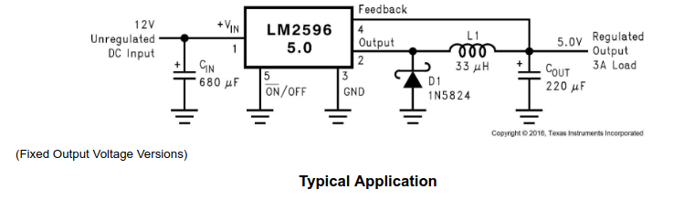
The component that you call out as being mounted crooked is the inductor, shown as L1 here. The buck converter works by turning on a switch in the IC which connects the 12V input to the pin on the IC labelled output and one of the terminals of that inductor. That voltage being higher than the output voltage starts current flowing through the inductor, storing energy in it. Once the voltage on the output is high enough, the switch turns off and the inductor then keeps current flowing to the output of the module via D1. Once the voltage drops enough, the switch turns back on and starts to charge the inductor again. That switching is why it’s called a ‘switch mode’ power supply. Because the IC is always either on or off, it’s much more efficient. The inductor and it’s ‘flywheel effect’ is where the voltage drop is happening, rather than the IC, so instead of a linear regulator where there would be 7V across the resistance of the regulator causing loss, there’s probably more like 0.5V across the IC and then 7V across the inductor while it’s charging. Then the IC switches off and there’s 0.5V across the diode and 5V across the inductor while it’s discharging. The inductor doesn’t have as much loss when this happens because instead of converting that voltage and current to heat, it’s converting that voltage and current to magnetic field energy and storing it/discharging it.
As for that component, that looks like the component may have been damaged. If you look at the other modules, I suspect you’ll see that the metal tab isn’t lined up with the body of the component any more. I’d guess it was soldered down fine because the tab looks like it’s on the board properly, but then the body has been knocked and has been pulled away from that tab, potentially breaking the tiny wire inside.
If you get a multimeter and measure the resistance between the two tabs on that inductor, you should see effectively zero. It likely has a resistance of a few tens of milliohms, which is super low. It’s still connected to the rest of the circuit, so that may influence the measurement a bit. Trying to measure it in both directions can sometimes help there. If you get different measurements in different directions, unless you’re measuring a diode or semiconductor, you know there’s something like a diode causing issues with the measurement.
As for the through hole joints and one being shinier, that’s and interesting observation. I don’t think it’s the issue here, but they should look mostly the same. Sometimes if one looks way different, it may have been reworked by hand after the main soldering process, which can be a clue to quality issues in the assembly process. A dull joint used to be an indicator of problems when using leaded solder, but a shiny vs dull joint isn’t inherently an issue with lead free solder. With those kind of joints, it’s typically the solder not having flowed completely around the joint or there being a crack that has formed, which usually looks like a dark ring part way up the side of the solder fillet.
That component is an inductor. The visible solder joint looks pretty good and I can see the toe of a solder fillet on the other one. I would guess that they’re soldered down fine. That looks to me more like the terminal is down flush to the board and no longer lined up with the component, meaning it has taken a knock at some point and damaged the component itself.

")