ok, short guide on how to set up a cloud tool library!
Step 1
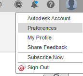
- To enable the cloud, go to the preference menu
Step 2
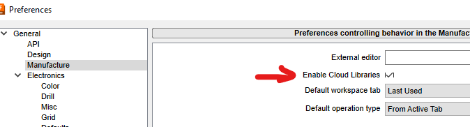
- Search for the “manufacture” tab and enable the cloud libraries & save
Step 3
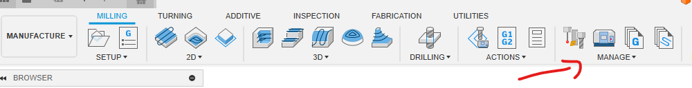
- Go to one of your designs, enter the “manufacture” menu, then “manage”
Step 4
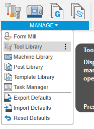
- Select “Tool Library”
Step 5
- right click on “Cloud” and select “new library”
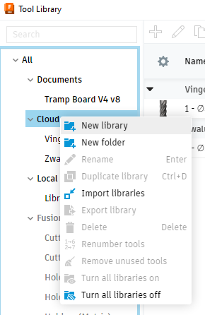
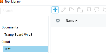
Step 6
- Next add a new tool to the library by selecting “+”
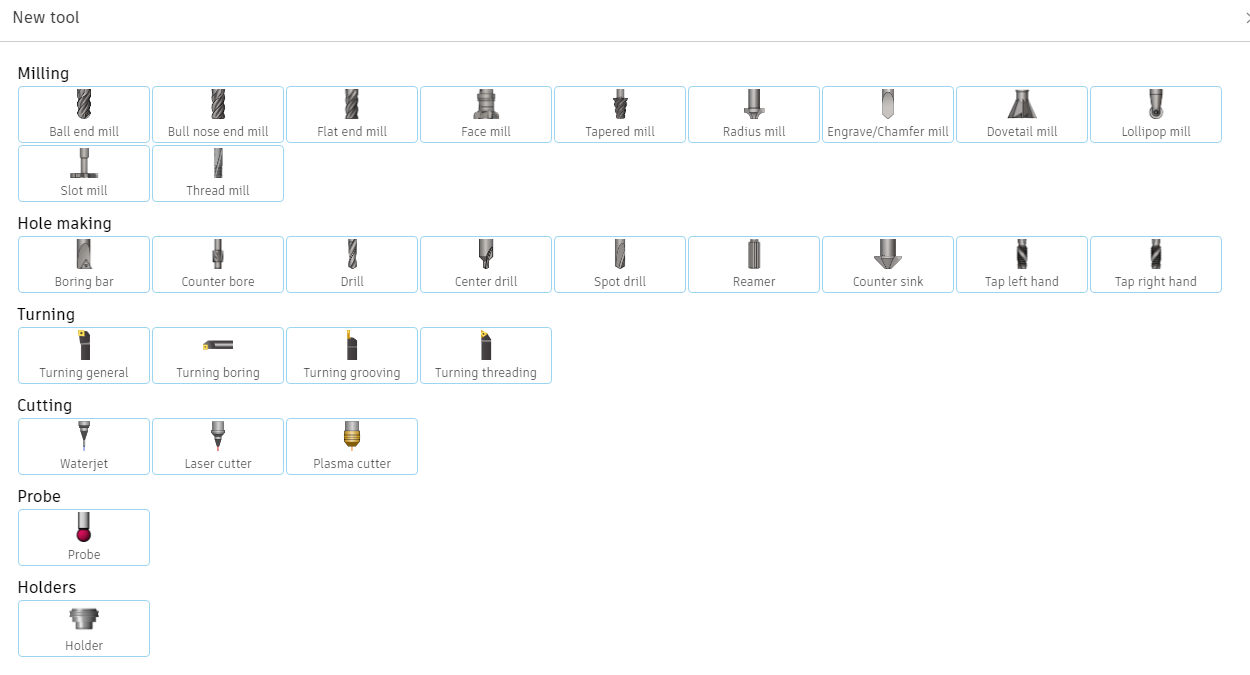
Step 7
- Select the tool type you are willing to add, just have a look at the images. In the example I´ll add a dovetail bit
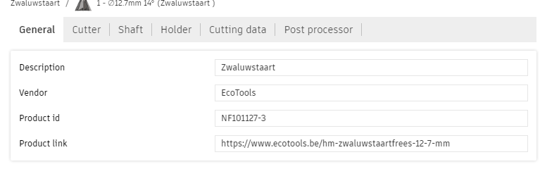
Step 8
- I find it best practice to add some generic info (below “General”), like the brand name and where I´ve bought it in case I want to replace it.
Step 9
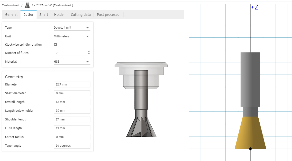
- now add the cutter info below tab “cutter”. These parameters you can all measure and define with your caliper. Some difficult ones like “angle” will most likely be defined on the webshop where you have bought it. When entering the data, the picture on the right will start to look like the real thing.
Step 10
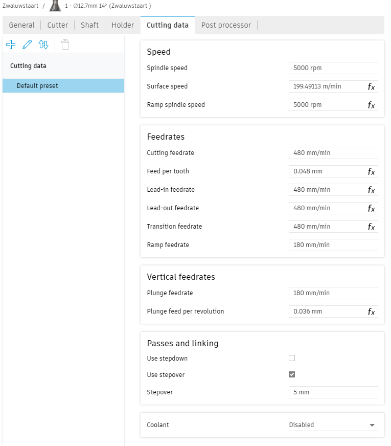
- at “cutting data” you will need to enter the feeds & speeds.
you will start entering them in a “default preset”. You can make as many presets as needed. You´ll want to do so for; cutting Alu, Plexi, Soft wood, Hard wood, … so you can later select the preset during Gcode creation without changing things manually.
Tip 1: read through this topic, people added valuable notes with regards to this!
Tip 2: have a look here!
Step 11
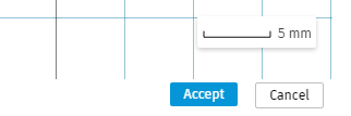
- lean back, press accept, and get excited as you´re one step closer to crafting something wonderfull!
note: no need to add “shaft” or “holder” data as our machines do not support this.