Thank you, but I was looking to use the sockets with TMC2209 for the standard axis XYZ, but needed external driver signals for a potentially tangential knife direction : the fourth axis would be knife direction. The knife I’m looking at has is own driver, so it only needs the raw enable, step and direction signals.
I saw that there is an external driver adapter, but I wonder if it works since UART is used to control driver on the Jackpot (that’s what spec sheet saying…).
The 6 Pack is for all external drivers, which is not my case…
Another point I need to mange is that the knife driver operates on 5V signals.
What would I get out of the Jackpot sockets 3.3V or 5V ?
From my reading of the Jackpot schematics, since ESP32 is 3.3V, I think raw signals are gonna be 3.3V out of the driver sockets. So I would need a level shifter to convert it to 5V…
Bart does make external driver adapters that drop into the headers on a Jackpot or any other polulu stepstick compatible layout.
The Jackpot uses 3.3V control IO, so you would need to have external drivers that can acccept a 3.3V signal. (Or, use level shifters)
The Jackpot does not provide ESD protection that would be advisable with a long wire run to an external stepper.
FluidNC should be able to configure any stepper position on the Jackpot version 1 board to use a “dumb” driver, but I’ve not tried this personally because of the 3.3V and ESD protection limitiations I note above.
In theory, this is possible. I haven’t bothered to try it yet.
My interest is for use with external closed loop stepper drivers, which I do eventually plan to play with.
I have a set sitting in a box with may MPR&P, but I’ve been a squirrel and haven’t done much with that machine lately.
Maybe a dumb questions :
Why should it need ESD protection between external driver and Jackpot?
Is this for signals integrity or for current rush protection ?
Are the onboard TMC sockets ESD protected ?
Because it is then external IO that gets plugged/unplugged and routes out in an environment that is potentially noisy and capable of being highly charged (e.g. dust collection ESD buildup).
Yes, and for actual ESD events.
Not the control signals, but there is some protection in the stepper driver outputs to the steppers.
In the on-board application, the jackpot IO isn’t exposed to the outside world directly so it doesn’t need any additional protection.
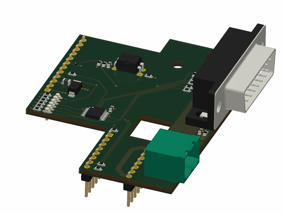
Following comments on ESD protection and 3,3 to 5V shifting, I’m working on a PCB adapter that takes signals from Jackpot controller and provides the 5V signals, 30V/5V power and ESD protections for the OTK-3 knife.
The PCB plugs into MOD1 socket and C axis sockets.
I’ve put DB15-SUB plug for easy connecting with OTK-3 who has a DB15-SUB female…
There are also leds for all signals.
I’ve got the following signals :
Enable - out
Direction - out
Step - out
E-Stop - out (powered or dry ???)
Home - IN (dry switch or signal???)
0-3V knife speed
5V+ control power
30V+ step motor power
The only things I’m not sure about yet are the OTK-3 E-stop and home switch signals, can’t find anything about with the OTK-3 expect, and Stepcraft hadn’t reply to my info request yet. That’s a bugger, I don’t like when a business doesn’t acknowledge requests even if they can’t answer…
Enable, step and direction from 3.3 to 5V. (and maybe E-Stop signal if needed)
3.3V PWM to 0-3.3V steady knife speed signal
Home input goes through an opto isolator to generate the 3.3V input.
The circuit would have TVSs, capacitors and ferrites beads for ESD. The DB15-SUB casing is couple to ground plane with capacitors and resistor for ESD…
You may want to look at the design of the 6 Pack Universal CNC Controller, too. A quick skim of the tangential knife manual leads me to believe that the 6 Pack board already supports what you’re looking to do. It supports a 0-10 volt output module and its stepper module outputs are already level shifted… Bart has a $2 breakout board for external drivers (without the level shifting of the retired board) for it, too.
The things is only the knife control is a 5V external driver, I don’t need external drivers for the regular XYZ axis. I don’t know, I’m just making my head around this project, maybe you’re right and using all external drivers, but it looks simpler to me using the internal TMC2209 drivers…
Yeah, that’s why I suggested the version for the stepstick drivers (same as you’d use with a Jackpot) and the IO modules. The stepstick driver pins are already shifted to 5V on that board.
What kind of stepstick should I use for the LowRider axis ? TMC2209 too ?
Instead of using a stepstick with an external adapter, could I config firmware to use pins for enable, step and direction on an MOD socket for the OTK-3 knife ? That way I could design a special MOD including the DB15-SUB plug for it…
So I could use the stepstick sockets for XYZ axis, and a special MOD pcb for OTK-3 plug.
The “special adapter” just loops the direction, step, and enable pins out to the motor pin header on the board, along with allowing you to select between gnd and vdd for common. You could certainly just connect your board to the stepstick headers.
I don’t think the module sockets are fast enough. For the Airedale IO Expander, Bart says that it wouldn’t work. I think it’s similar for the case you suggest.
If you’re going to go the route of creating a PCB board, I wasn’t meaning to deter you from heading down your original path… just suggesting another design for the level shifting for reference. Using the 6 Pack board and some I/O modules, and just wiring things into a DB15 connector does seem like the path of least resistance, though. It all depends on whether you’re looking to spend time on your interface board project, or if you just need to get something working so that you can start using it.