Observing that milling holes quickly whips around at full feedrate during flat segments, is this normal and expected? Or, would you expect smoother motion through out the overall hole plunge? e.g. making 5.3mm holes with 1/8" bit. I’ve been using the same tool settings for contour cuts and holes.
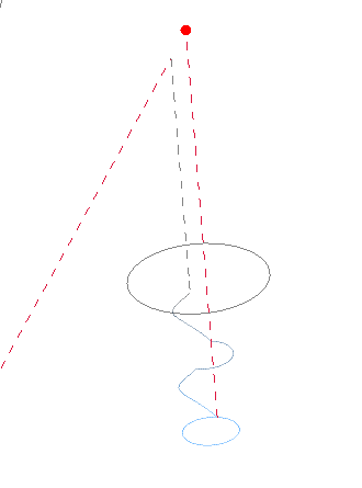
Forgot macro lens, so not focused, but you get the gist.
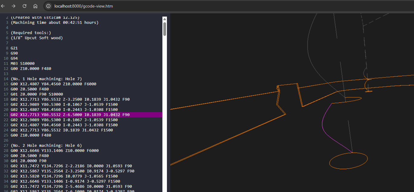
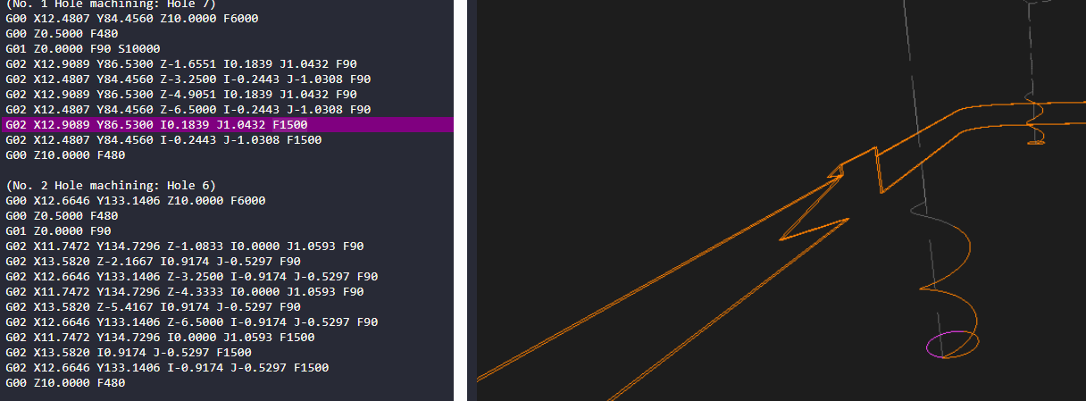
Using an alternative gcode viewer, can see plunge feedrate 1.5mm/s (90mm/min) used during ramped plunge. But, flat segments switch immediately to full feedrate, this matches up with behavior observed in the video clip above.
Editing settings and reducing ramp angle from 45deg to 10deg would help result in .gcode that has more consistent slower ramp speed through out the plunge…
Posting to see what’s normal/expected? Am double checking my acceleration values (fluidnc firmware settings), maybe I fiddled with those at some point…
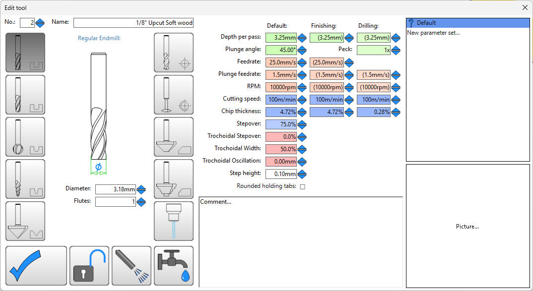
That’s normal. You have the plunge angle at 45°, so it goes down in a spiral at 45° and then clears the rest in the “normal” speed. Since your holes are tiny, it looks kind of odd. I don’t use 45° so mine just goes in and then does those rapid movements in a circle. It’s easier to see with a bigger hole. Try a 30mm one and you will see what I mean.
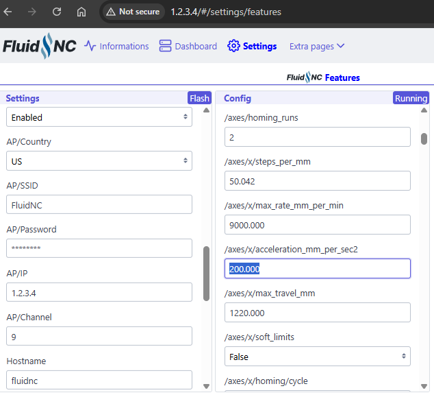
Editing acceleration_mm_per_sec2: to be 100 instead of default 200.000 for both x: and y: axes results in XY Rapid motion between cut motion being more reliable for my build.
My build could probably do with additional belt tension tuning. Feels like belts stretched over time. I’ll check if steps/mm need changing…
Thinking lower default acceleration of 100 would provide Makers with larger window for success?
Thanks for this info. The standard V1E Marlin configs used 180, 180 , 80 (X, Y, Z), and I ran into some skipped steps issues from too high acceleration when I increased the X & Y max feedrate beyond default
Plunges are typically machined at Z feedrate and flats at X/Y feedrate. The primary issue is that your X/Y is 1500mm/min and Z is 90mm/min (really slow) so the difference in (ramping) plunge and flat speed is really noticeable. Cutting ~6.5mm deep Holes with a depth per pass (DPP) of 3.25mm typically means there are two (ramped) plunges and two flats. Playing with ramp angles to get rid of the first flat is unnecessary when drilling helical holes.
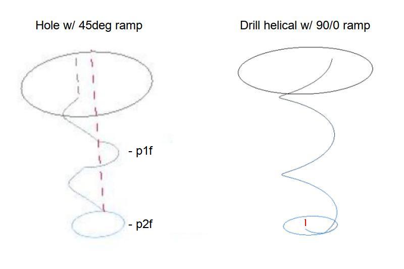
Helical holes have ramped entries by default. The default helical ramp angle angle seems to be based on DPP (smaller = shallower ramp) but can can usually be reduced by setting a really shallow ramp angle. Helical holes will be done as a single Z feedrate plunge on holes up to 1.75x the tool diameter, e.g. 3.175 tool x 1.75 = 5.556 (> 5.3). There will still be a switch to X/Y feedrate at the bottom of the hole (v12, v11 < 1.9x is Z only).
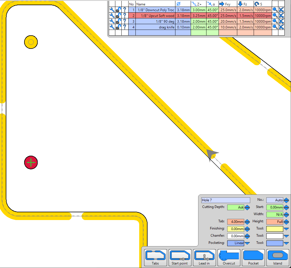
When the hole is bigger the tool will plunge to DPP, switch to the X/Y feedrate and spiral out to expand the plunge hole, switch to Z feedrate, plunge DPP… Even with a X/Y feedrate that is 2x (VS 16x!) the Z feedrate, the speed change is noticeable and X/Y seems really fast on small holes (VS straight cuts). Setting up a small hole ‘tool name (dupe)’ (won’t cause a tool change) with a smaller DPP and a really shallow ramp could allow setting equal feedrates, e.g. increasing Z feedrate and decreasing X/Y feedrate.
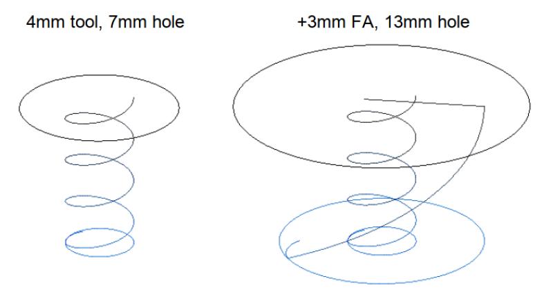
Adding a same tool finishing allowance (FA) to cut bigger (than maximum single plunge) holes is significantly faster than cutting small stepped (Z > X/Y > Z…) holes. While holes up to 3.25x the tool diameter can be cut with a second full depth FA plunge (steeper ramp), going that big requires a large (e.g. 75%) stepover. This seems best suited for holes that are closer to 2x tool diameter, e.g. 8mm holes with a 4mm tool, P1: 4 x 1.75 = 7. P2: 8 - 7 = 1, 1 / 2 = .5 FA).
Single plunge math:
Minimum tool diameter for a single full depth helical plunge
hole diameter / 1.75 (v12, 1.9 v11)
Maximum hole diameter for a single full depth helical plunge
tool diameter x 1.75 (v12, 1.9 v11)
Two plunge math:
Minimum same tool finishing allowance
(hole diameter - 1x max hole diameter) / 2
Maximum same tool finishing allowance
(tool diameter x 3.25 (v12, 3.65 v11)) - maximum 1x hole / 2