And once you hot a certain point they don’t really add anything to the structure. The X rails are very rigid so there is extremely little flex between the braces on the rails as suggested. You might be able to add one extra but you will need to measure to see if your board box fits in the gap.
We are a bunch of tinkerers at heart. It is hard to get people to try it as is before “improving” it. Blessing and a curse, that is why I love this crew.
I bought this super cheap ($8) pipe cutter did nice work cutting the conduit. I then deburred with a Dremel.
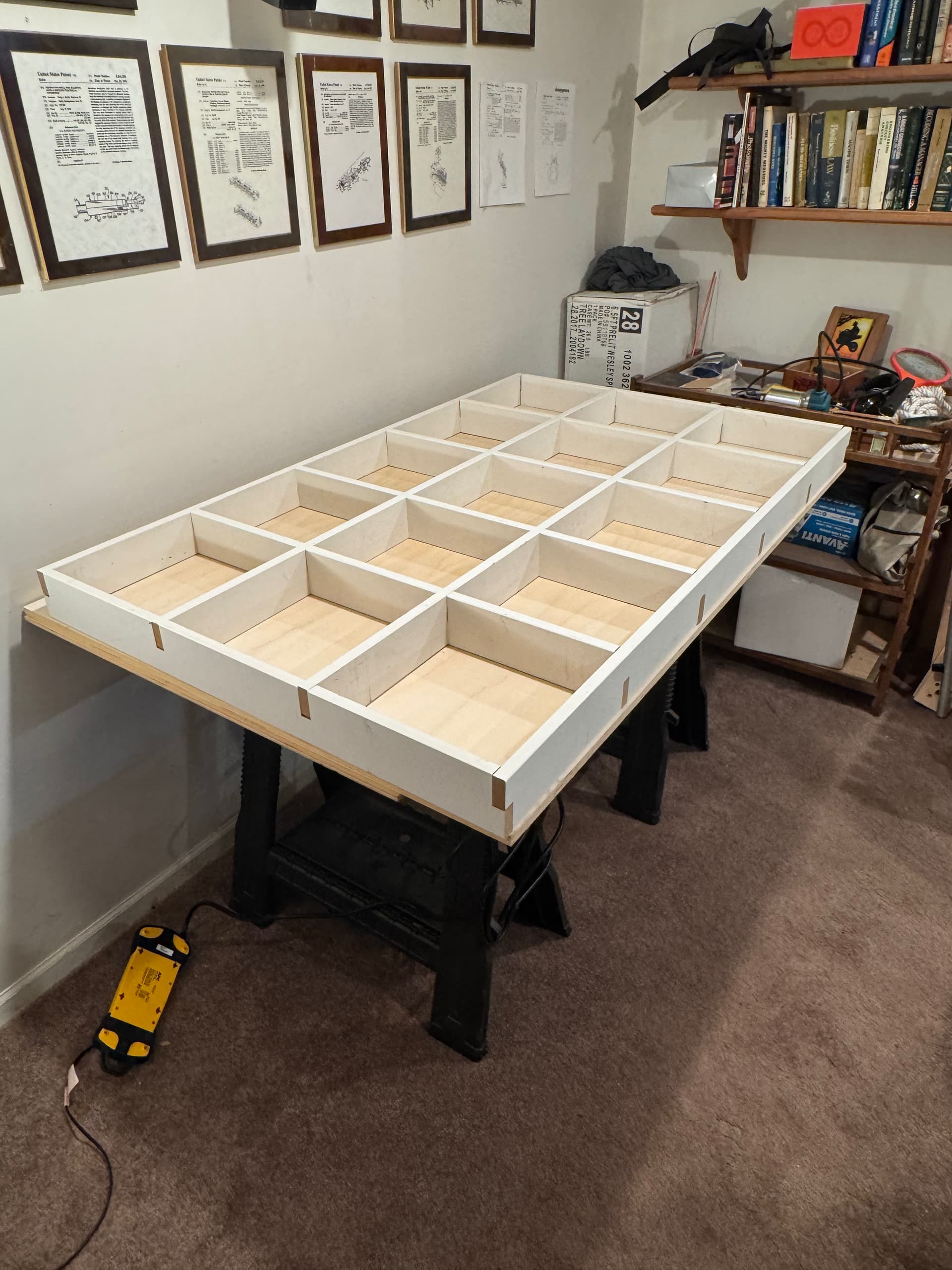
Ready to wire everything up to my Jackpot controller and route all of the wires. Realized my temporary table top was just a tad too narrow so decided to make a proper torsion box table.
Partly because I am getting nervous with the next steps and am more comfortable on the woodworking side Kind of joking, kind of not.
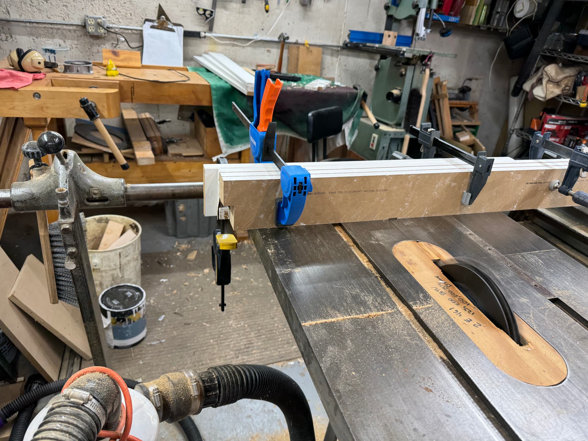
My build for LR4 will be 2’ x 4’ so my table is 60” x 37”. I just decided to use Fusion for the parametric modeling (again to delay actually finishing my build). I used the primed MDF 1x 4 trim. Good solution and pretty cheap. I am doing the top and bottom with baltic birch.
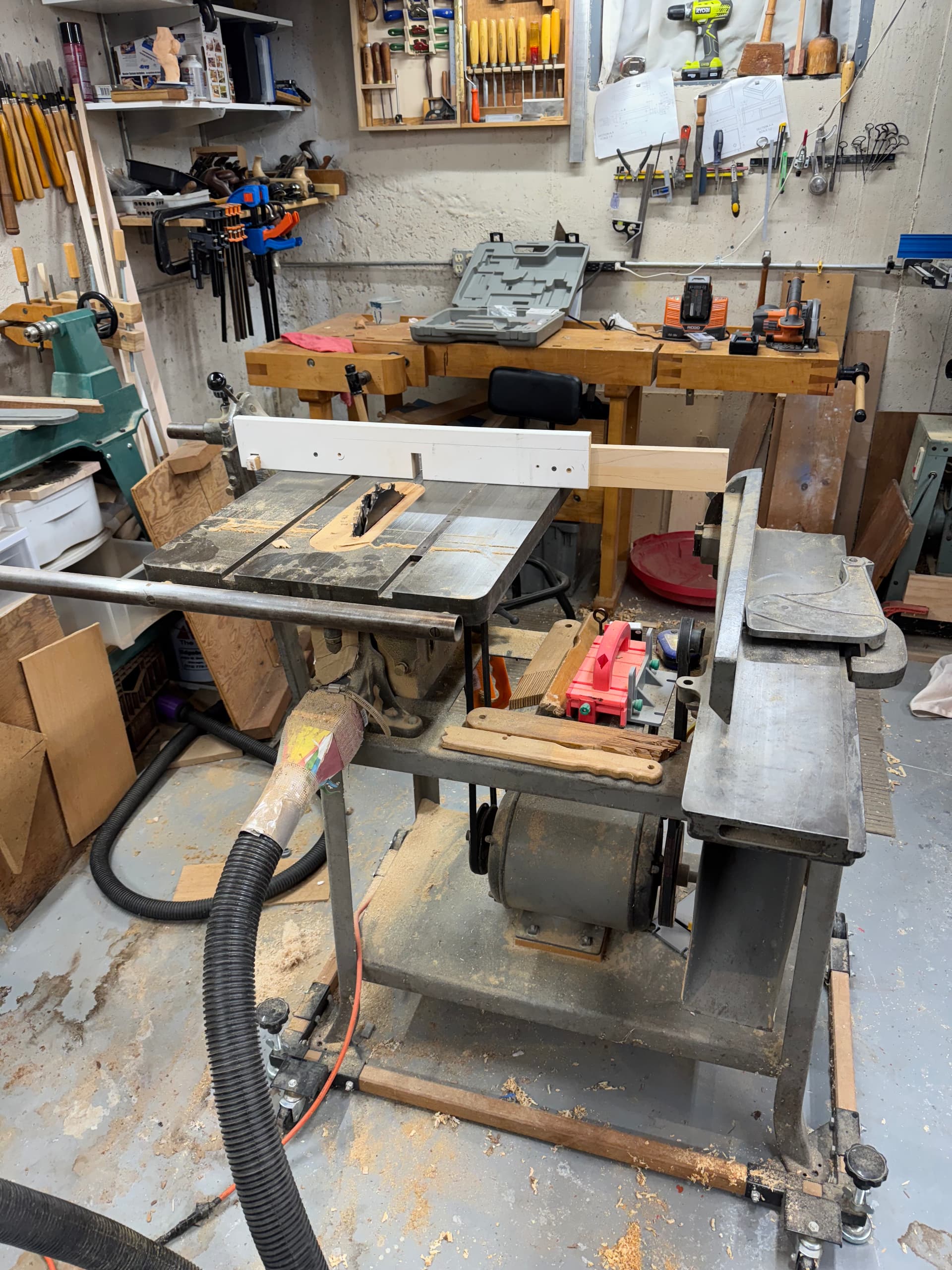
This is my beloved Delta 10” table saw 6” jointer combo I bought for a $100 at family department store I worked at (Oak Park Illinois) that went under. That was 40 years ago when I was 16. It is a 1941 year vintage Delta and notice the table tilts not the arbor! But served me so well. Original motor 84 years old!!
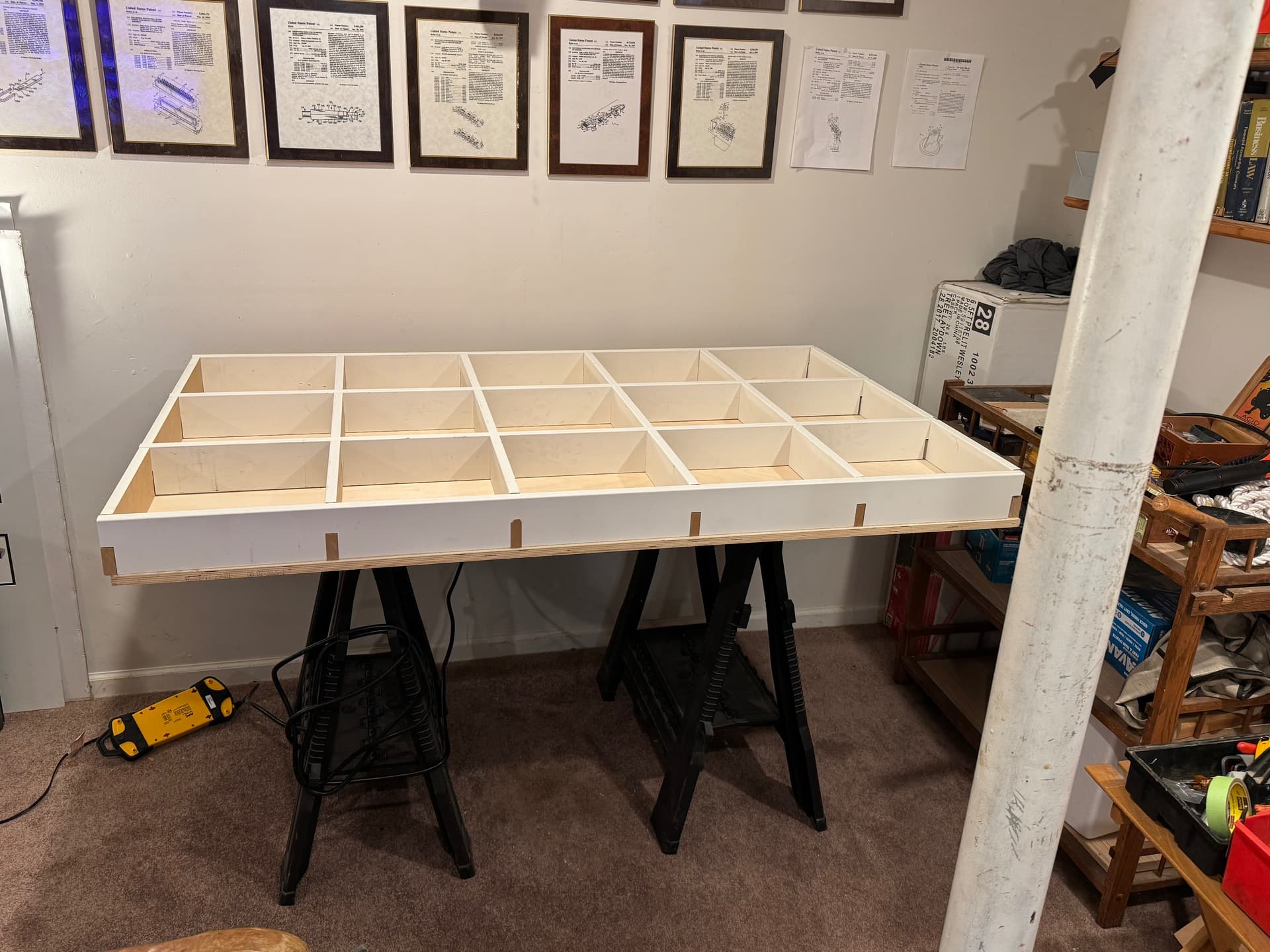
Turned out nice and even. I was going to glue the 15mm (5/8) Baltic birch top but too heavy and overkill. I will just shoot 16 ga. finishing nails in. The bottom I have some 3/16 particle board or what ever they call it.
I was going to mount some the same 1 x 4 MDF onto the top as runners. And then get back to the rest of the build.
I am feeling sorry for my MPCNC Primo which is moved over to the side felling neglected
Sorry probably obnoxious they were in the photo. I was at Molex for 30 great years in product development. This is my basement and I always kept them piled in the basement. Never thought about them. My son and son-in-law suggested to just hang them up. They are good reminders of a good time.
One is when I just graduated from University of Illinois BSME and worked at International Harvester which at the time was on the Fortune 5. I was in the large agricultural tractor group at the R&D center. Of course we got a new CEO who decided to break the union and the company almost went bust. Had a 6 month strike. Anyway that patent was having the controls tilt with the steering controls all human factors (tall to short) could see all of the instruments.
Anyway went to Molex working on “connectors” I literally thought what could be more boring!!
One of the cool patents up there is LFH (low force helix) that Cisco adopted. We crammed 60 pins in a 15 pin VGA shell. That became DVI which at the time was cool. Anyway sorry long answer for a short question.
very cool. Not a small feat to get one. A lot of time and money gets invested to go through the process. I have a couple and they probably aren’t as cool as yours. DVI was industry standard for a while, so that is big impact stuff. Now we use displayport right? Thanks for sharing!
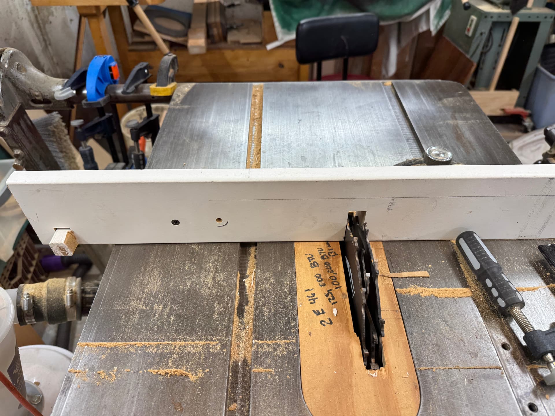
It was made for a dado set. Even came with “shaping” bits. Scary spinning shaped profiles. Before routers. Cove bits, Roman Ogee, etc. Scary.
But this was before riving and a tilting table does not allow it. I did modify to add but only at 90 º
I do have a great cyclone vacuum system. Actually works.
Bigger issue no guard. But I grew up on the school I love to see the horrible blades. Some felt guards let to false security.
I finished the table but seriously nervous about the wiring up the controls and the next steps.
But this forum has my back
Finally how depressing I realized today while I love my saw/jointer that 1941 when it was built was only 14 years BEFORE the year I was born!!! I bought it at 16.
One of my languishing projects is to get my grandfather’s 1934 Craftsman wood lathe operational. Currently it’s mounted to a stand, but I’m in “analysis paralysis” about whether to fit a treadmill motor to get variable speed, or try to wire up the extra V1 Engineering ac control board I ordered years ago to the original motor and use an optical sensor to get that variable speed control.
That is really cool that you have it. I do like old vintage tools. I don’t know much about variable speed motors or control. Treadmill motor would be interesting.
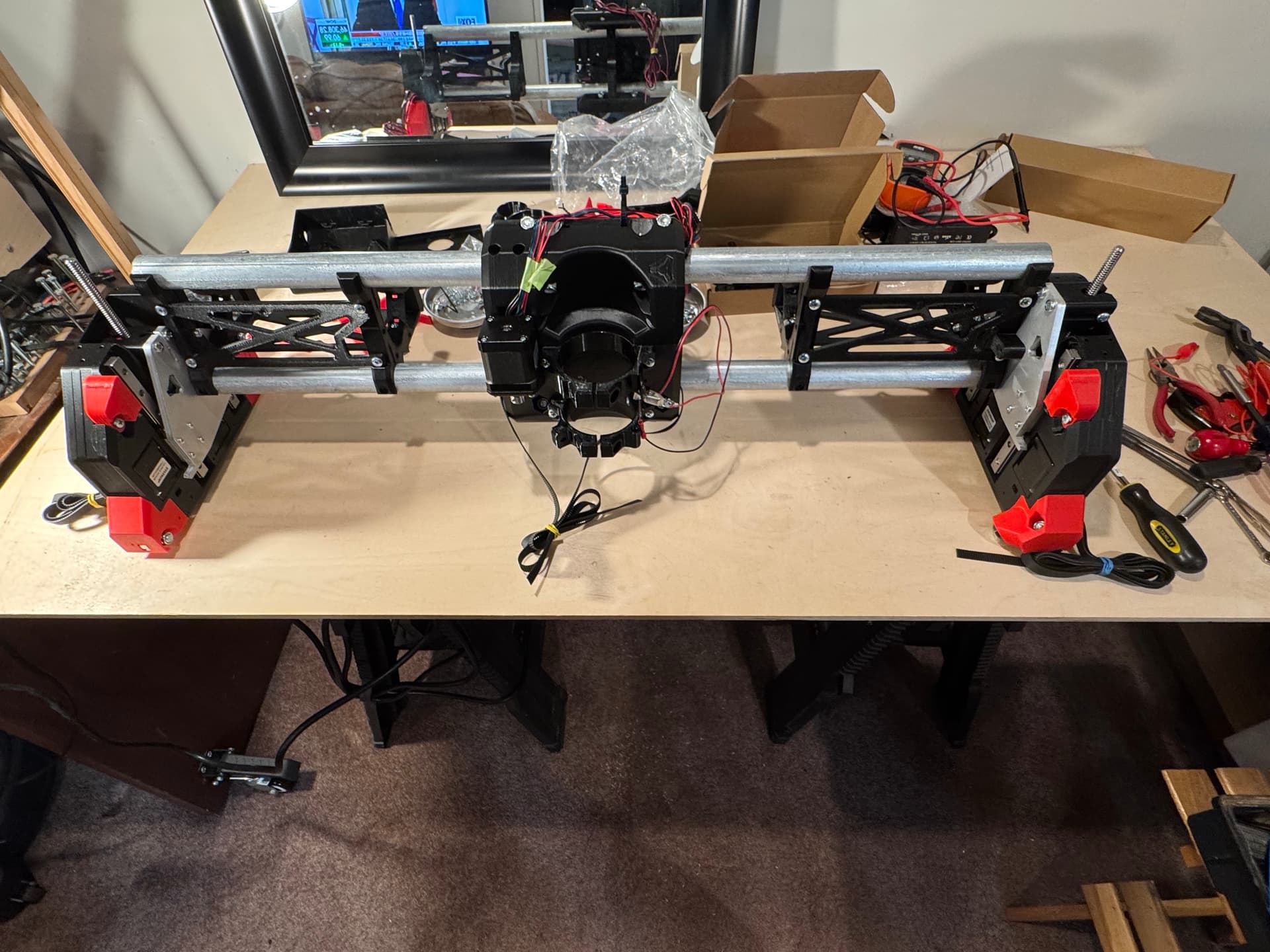
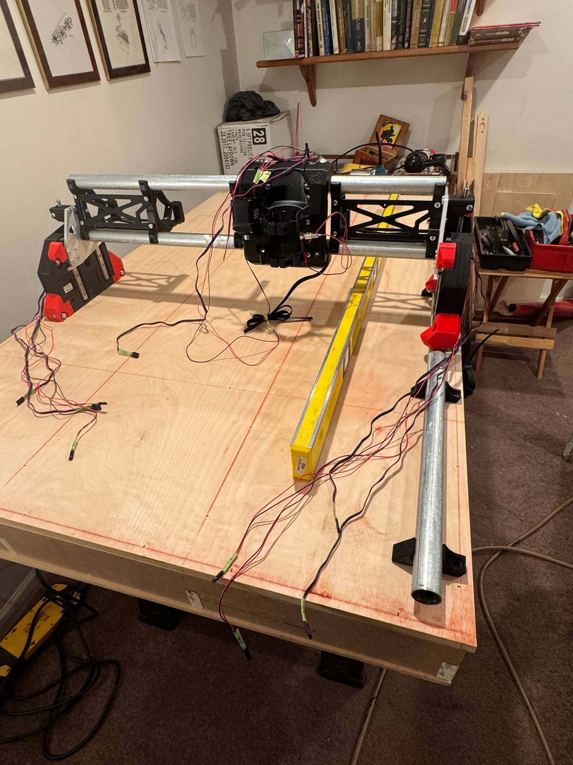
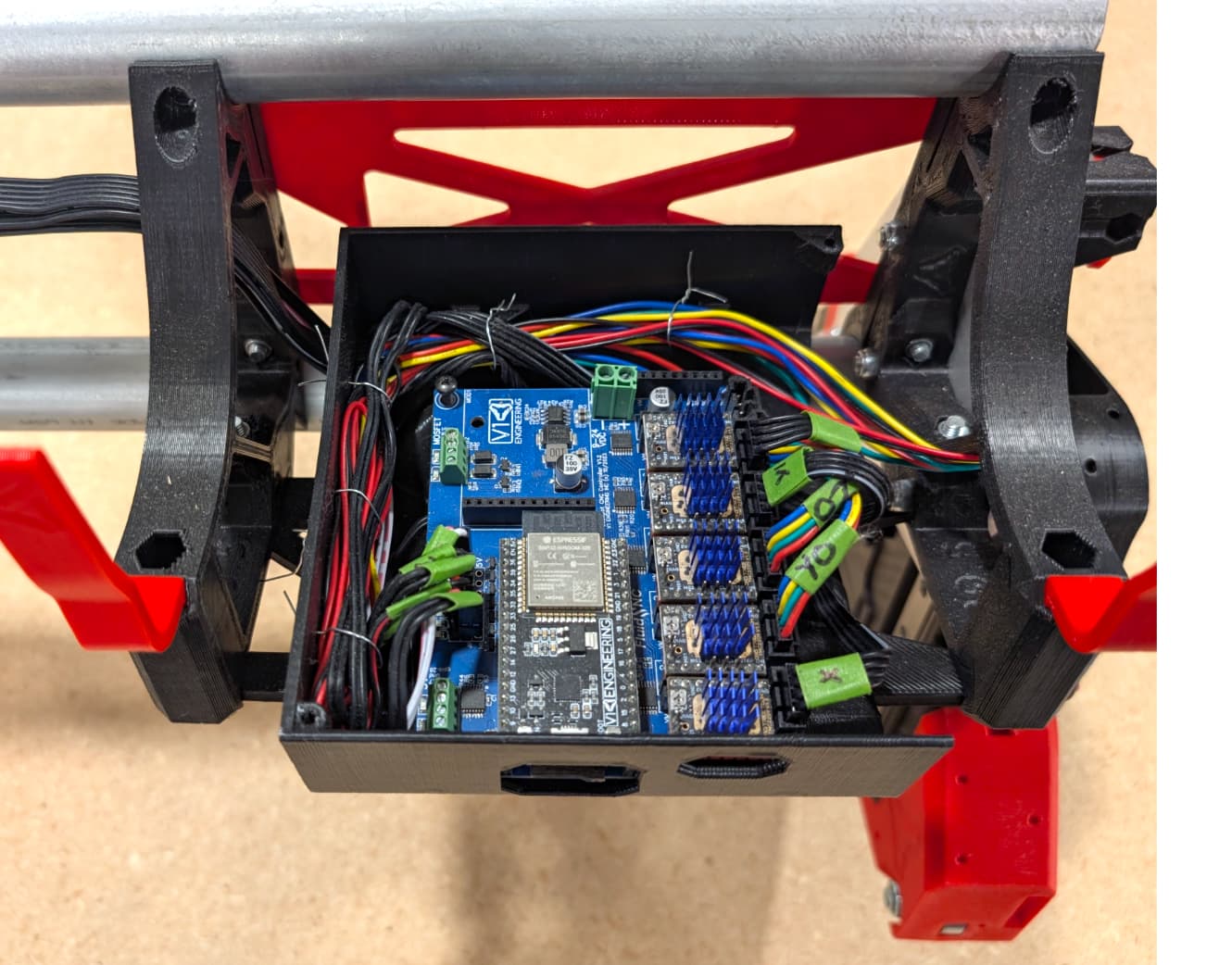
I finished my grub screw Locktite and did all of my primary wiring.
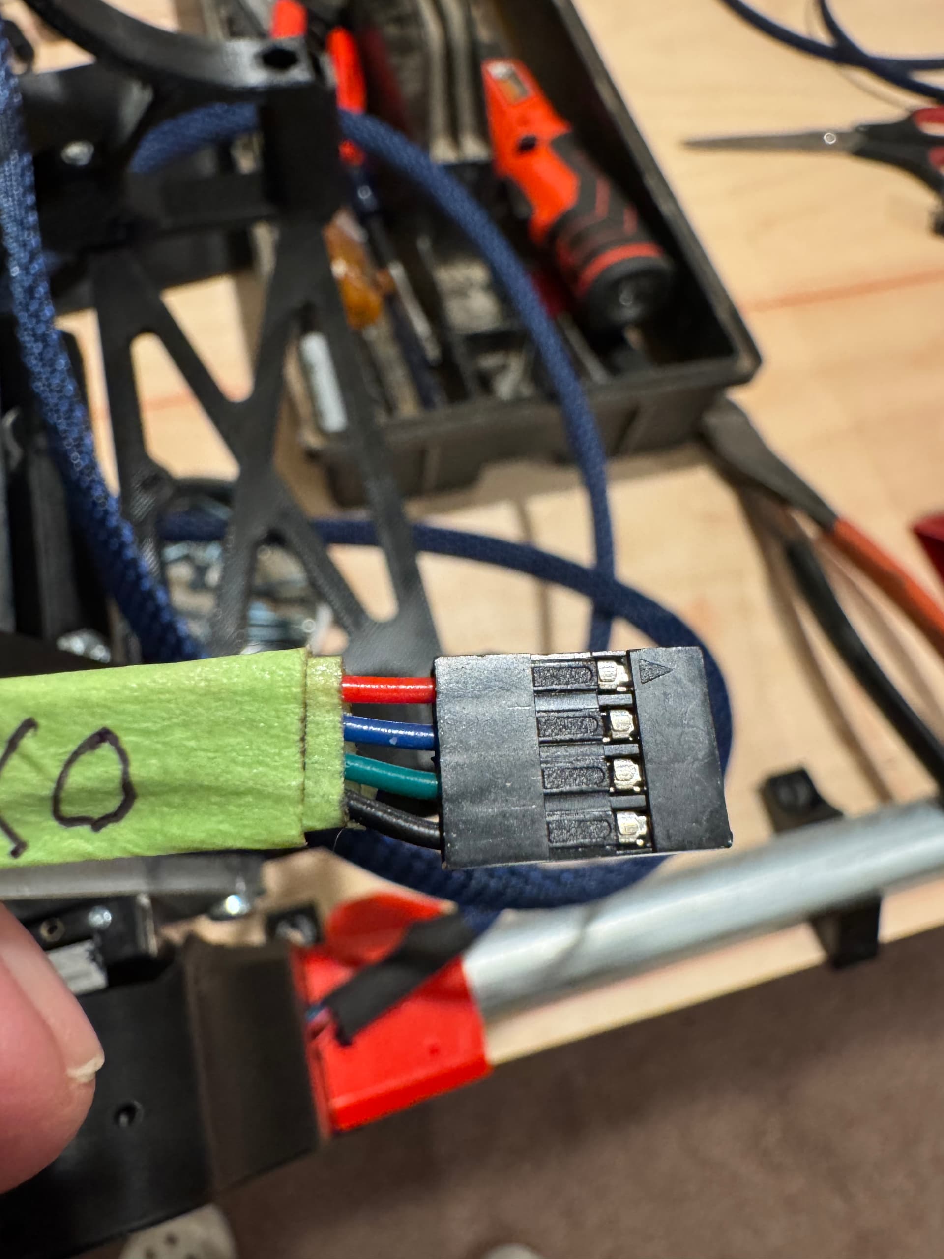
I am embarrassed to say as a retired connector engineer I failed to pay attention to the circuit one identifier on the Molex SL/DuPoint stepper motors. And of course put the braided cover over it all then I realized my mistake and took apart.
The little circuit one identifier arrow. It now matches up with Ryan’s nice extensions. Of course I did it backwards as I forgot about the polarizing circuit one identifier.
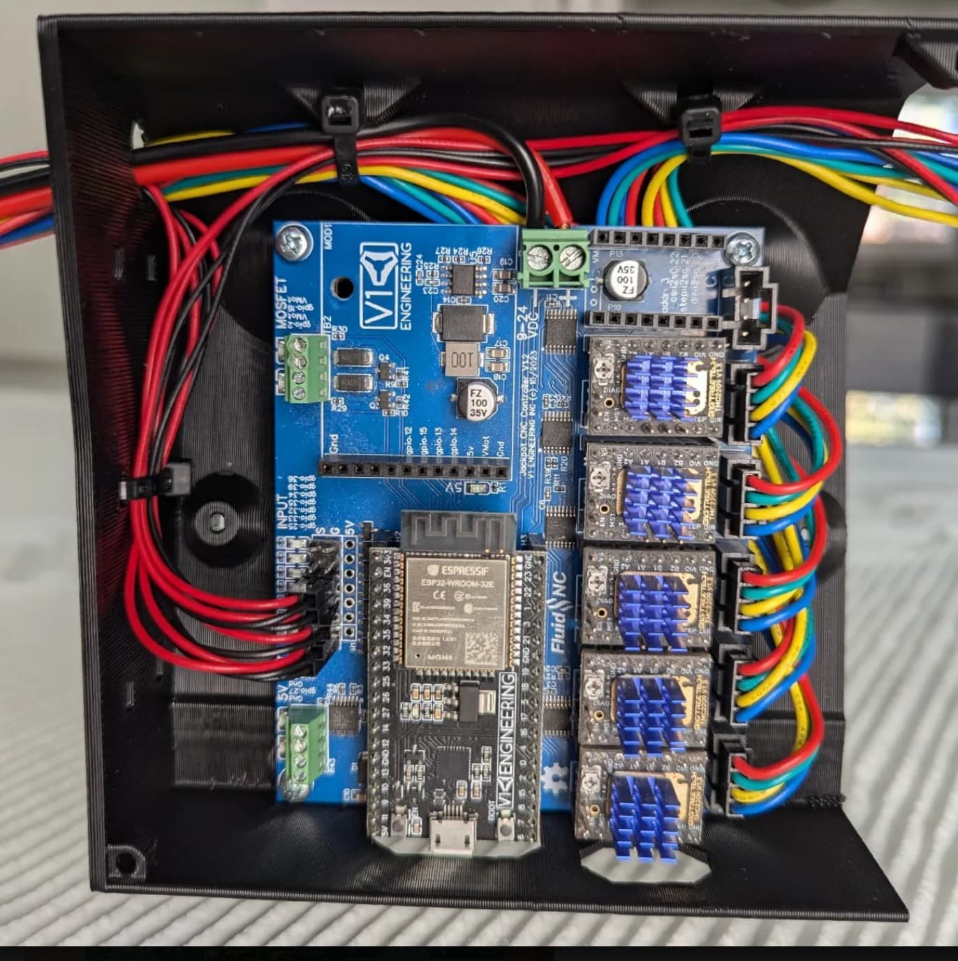
I am confused about how the stepper motor connectors plug into the Jackpot Board. I assumed I missed that part. I did not run my belts yet so maybe it comes later.
While this one shows the opposite? These are both screenshots from V1E.
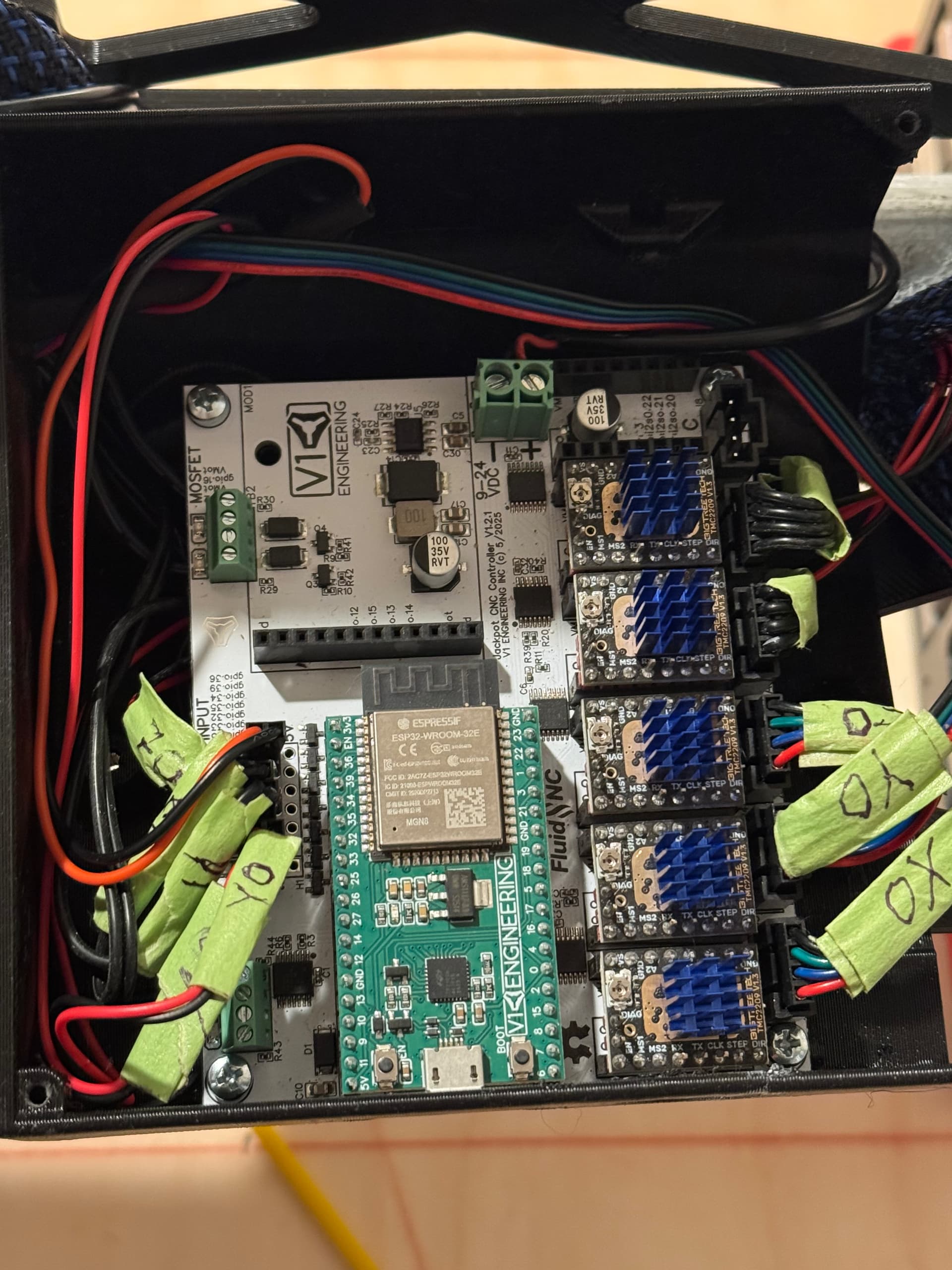
So I am not sure? Also I assume since the microswitches as well as the touch plate are basically plain open/close switches polarity does not matter even though I put the RED in along the edge.
This is how I wired mine. BTW which version of the Jackpot board is this? Does it matter?
The direction doesn’t matter, and the wires colors can vary per stepper. Once you try to move the machine if they move the wrong way all you have to do is power down completely, flip the plug over, power up and the stepper will move the other way. Easy