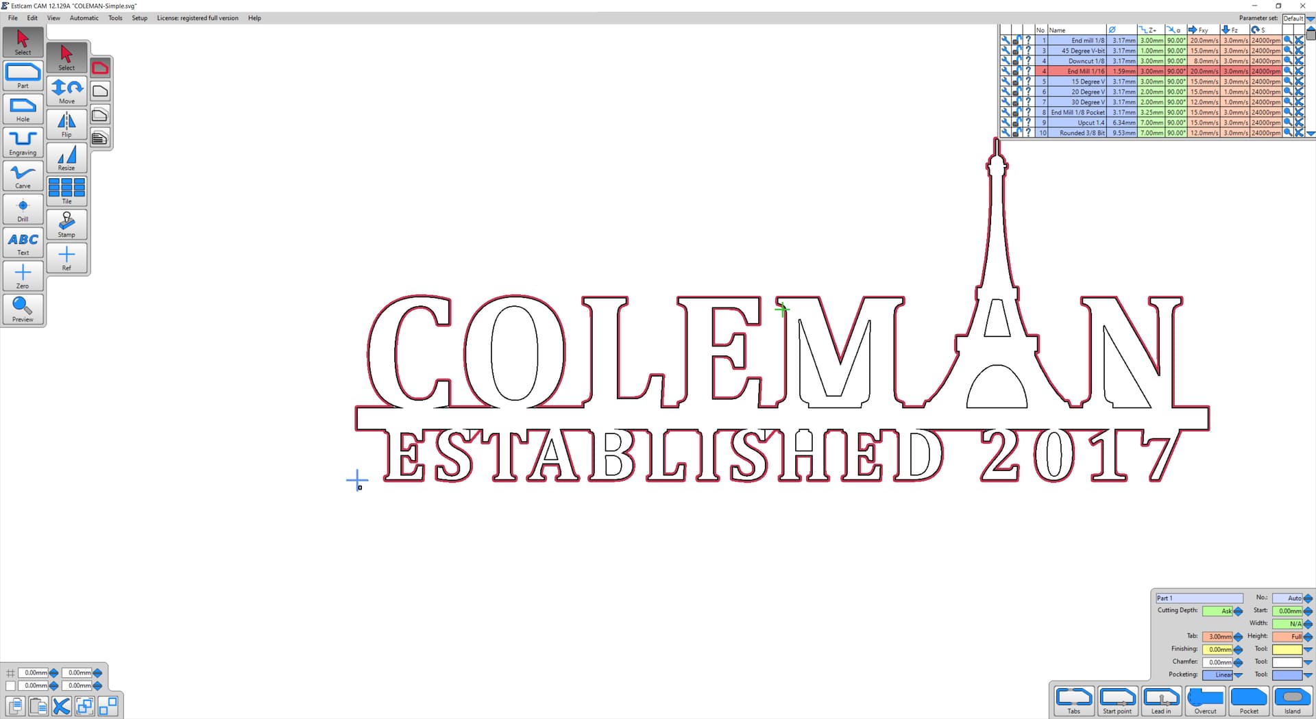
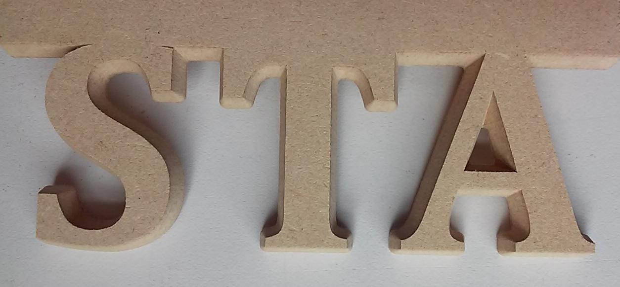
If I use the 1/16" bit, there are some parts of the path that don’t look right. There’s an angle instead of following the line at the top of the two “S” charachters in ESTABLISHED. If I use a 1/8" bit, it appears normal. I even tried just changing the 1/8 bit to a 1/16 diameter and the same weirdness showed up.
I can work around this weirdness by creating a manual part around that spot and finish cutting it out. Or I could use a 1/8" bit too because I don’t really need that level of detail for this sign. It’s just what is currently loaded in the tool. I would just like to understand what went wrong either with my Estlcam setup or the SVG so I can avoid this in the future.
I thought that, but I double checked it. If I slide the node in the corner over so it is straight up and down with the other, it works fine. Slide it back and the same issue occurs.
That is strange. @christian-knuell may want to get a copy of the project file and a version number of your estlcam.
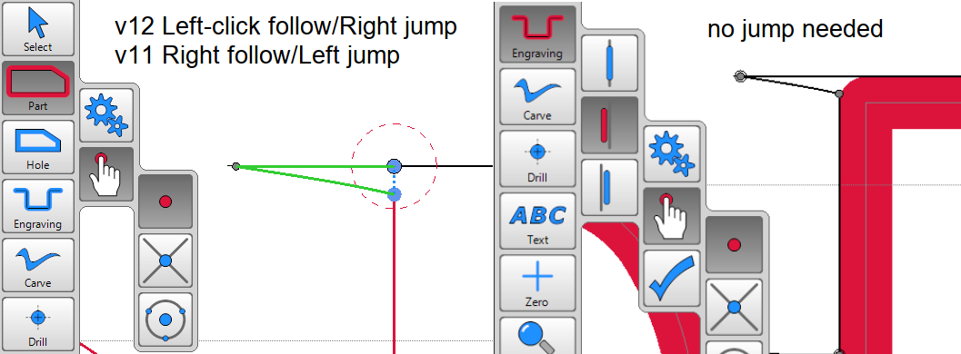
In the meantime, you can use the manual trace. If you jump ahead and bunch and the green line looks right, you can right click to accept that progress so you don’t have to trace everything. It is hard to describe, but it will only be a few extra clicks. Most can be trusted automatically and you just have to trace near those S’s.
2mm works but anything less than 1.8mm doesn’t (v11 and 12). As has been mentioned, using Manual shape detection (faster/easier w/ v11) is a workaround (for <1.8mm). Parts (and right of the line engraving) require jumping the gap on the top right of the S’s.
If you don’t mind bidirectional or climb cutting, left of the line engraving works. Using v11, …three clockwise perimeter right-clicks will create a bidirectionally cut part path. To make it a climb cut path add a finishing allowance and a (same as roughing) finishing tool. Using v12 requires more mouse clicks and can only create a bidirectionally cut path.
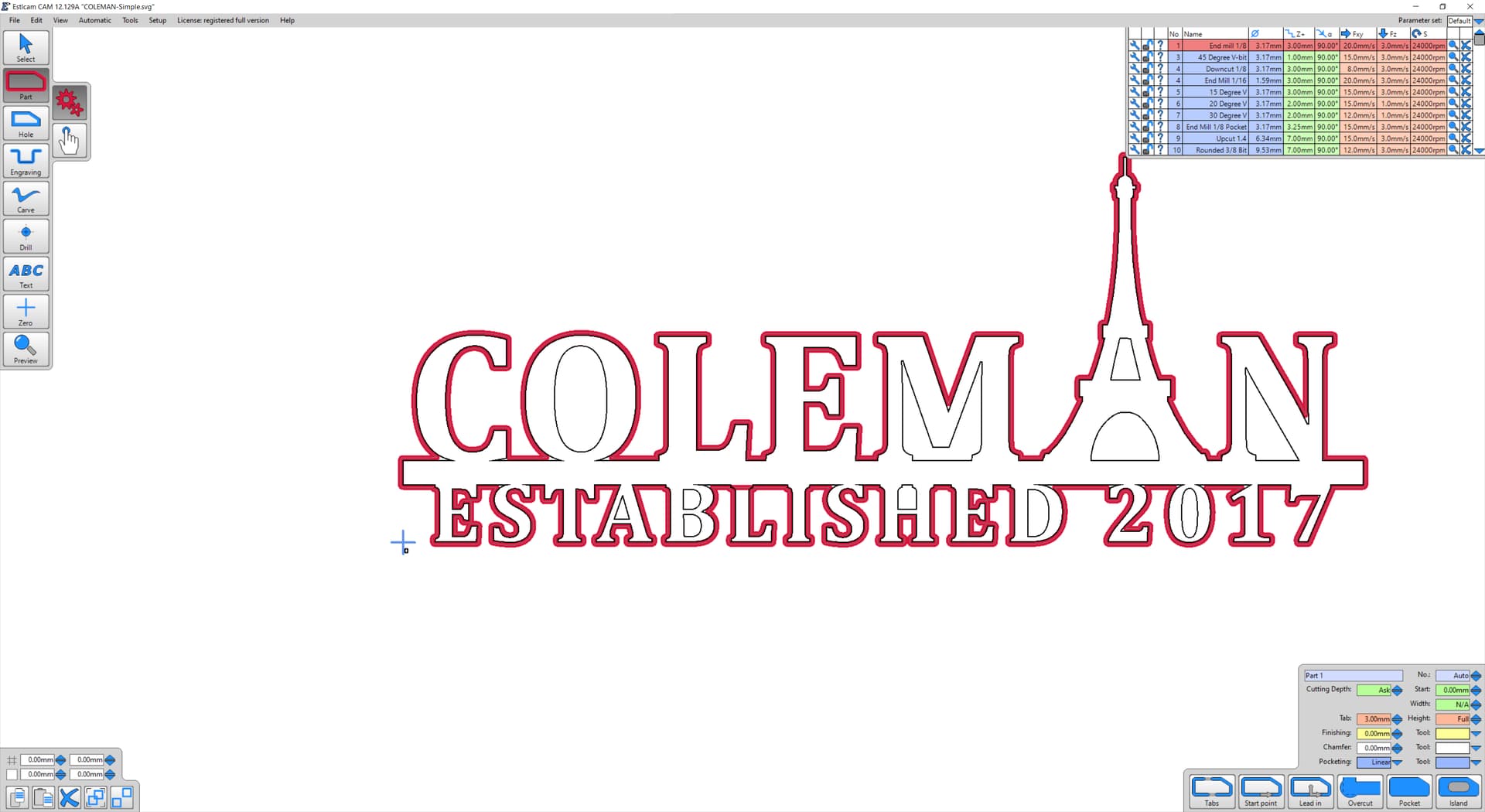
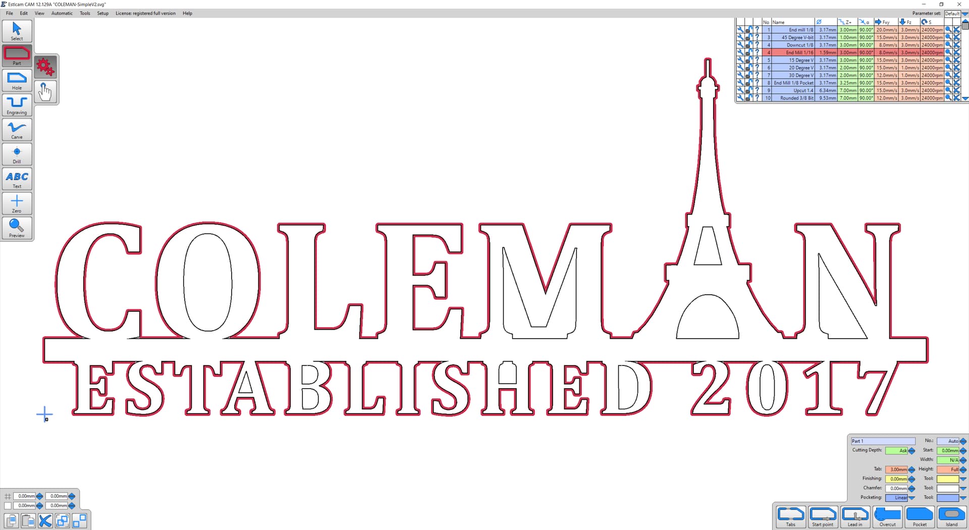
For some reason Estlcam has multiple problems with the drawing (which doesn’t seem to have any issues). To expand on my original (corrected) reply there are issues when the tool diameter is less than 1.8mm and greater than 2.8mm. When the tool is >2.8 the path jumps across (and backtracks back across) the top of the bottom L (see 1/8" bit/2nd image above), I and 2 (depends on tool diameter). I don’t know of any workaround for those jumps.
An alternate approach is a Carve (and Part) path. Adding a Part path allows tabs (and deeper cuts). For the Carve path decide on a depth and then use a calculator (e.g. Dave Lers : Workshop : CNC : Estlcam : Carving) to determine/set the Carve Width (Depth can be left at the default). The Carve path and Width are a LOT faster to set using v11 - seconds VS minutes.
For this drawing’s Part path use a 1.8 - 2.8mm tool and set the Finishing allowance to half the Carve Width or less (to get into the corners better). The part path will likely need to be manually set to bypass the insides of the bottom E’s which would get separate Hole paths.
The example was done with a 6mm 30deg bit Carve path with Width set to 3.5 (6.53 depth). The straight bit engraving path was 6.54 deep and offset .5 less than 1/2 the carve width.