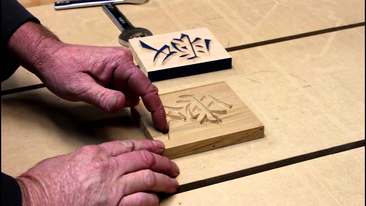
Perhaps this should go in Troubleshooting, I am not sure. I do not believe the problem is with the machine, but in my use of the Estlcam software.
I’ve watched the v-carve tutorial here:
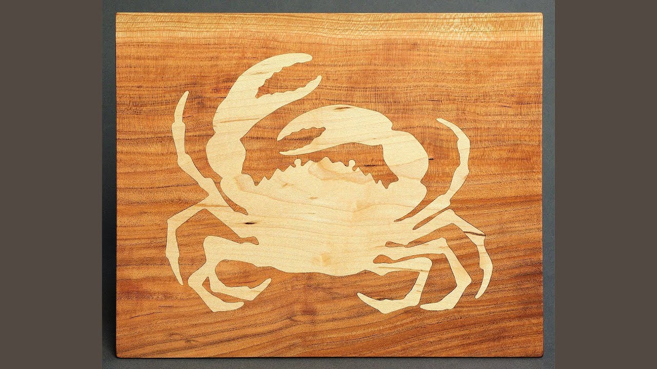
An I am able to reproduce this result. Now I want to go further, and fill the pockets with wood instead of paint. So, I found some videos:
http://forum.vectric.com/viewtopic.php?f=39&t=7241
And I try to reproduce it myself. I have attached some Estlcam project files, g-code files, and svg file on which I base my design.
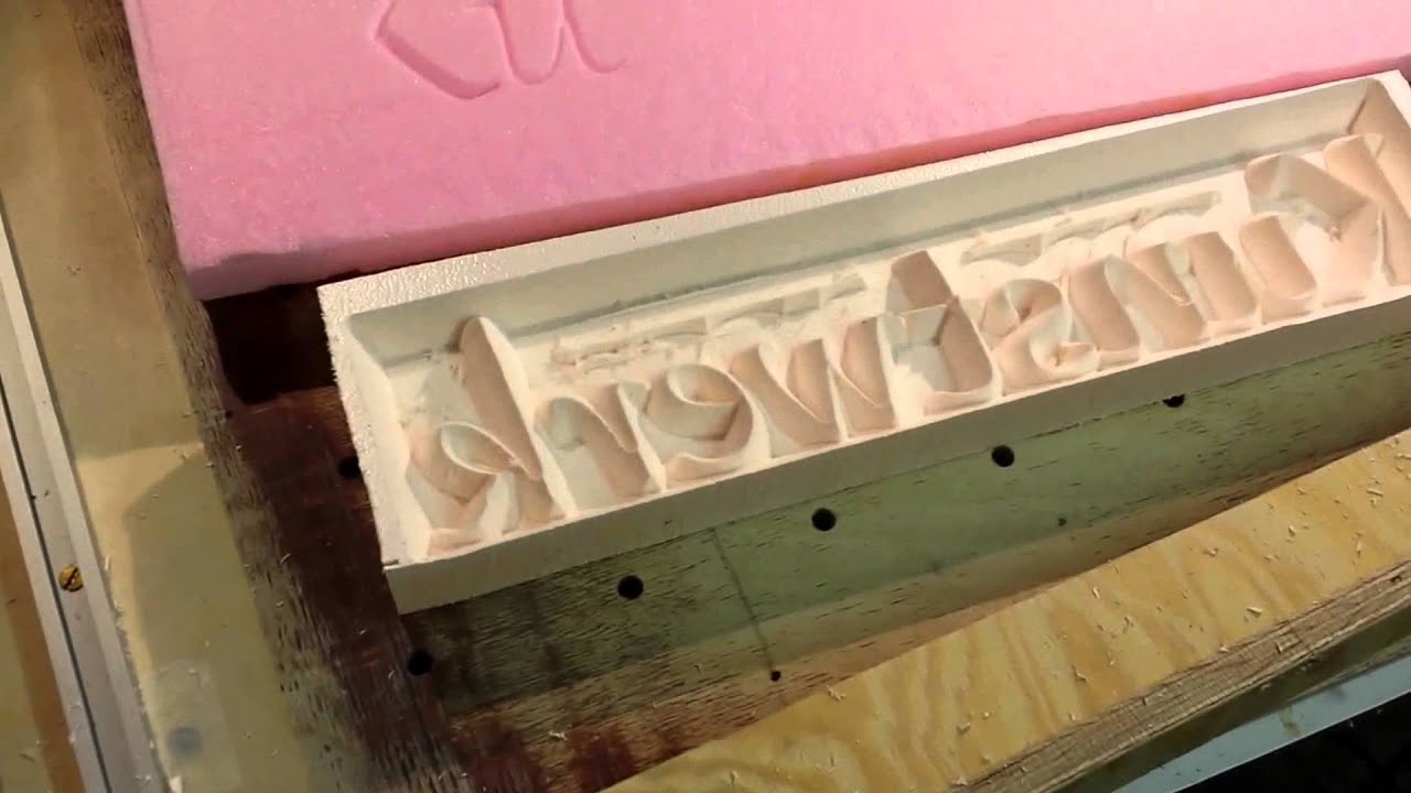
I am using a 1/2" diameter 90 degree V groove bit. For the female piece, I set start depth to 0 and max toolpath depth to 0.2. For the “male” piece, I set start depth to 0.1 (to shrink the top to create overlap) and max toolpath to 0.4 in an attempt to get more overlap room in the sharp corner area. It was unsuccessful and produced vertical sides in my second attempt. Router output seen here:
https://imgur.com/a/AdnJ7
https://imgur.com/a/ogI6E
https://imgur.com/a/S4GHG
As seen, the pieces do not align properly, because of rounded corners I think, but I cannot see through the pieces. Taller K unexpectedly has
vertical sides. I hope with this technique to get sharp corners always. Clearly I am a beginner, and the problem lies with me instead of the
program or router, but I am unable to see the problem.
Is Estlcam able to make this kind of inlay? I find Estlcam very easy to understand for most operations, but doing this kind of inlay was a primary goal in building my MPCNC, so if Estlcam cannot do this operation I must look for other softwares.
Much thanks in advance for any help ![]()
vtest.zip (383 KB)
