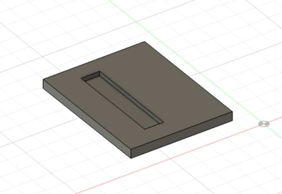
Apologies up front for the basic question. I have learnt the very basics of ESTLcam and can cut shapes, lines etc. I would like to cut something like the following:
For the “dado” like section is there an easy way to do this? I see hole and part which don’t fit so I guess I need carve. But carve also just wants to follow a line it seems.
Do I need a dxf that has a line in it that can be followed?
I was thinking that, but I’m sitting on the couch and don’t have access to estlcam at the moment. Didn’t want to throw a term out that doesn’t actually exist.
When you author the DXF, round the corners to a radius just larger than the radius of your router bit for both the mortise and the tenon. Alternately you can dogbone the mortise.
If you don’t do one or the other, your pieces won’t fit together without some work. Pocketing will leave the corners of a square pocket round.
I’ve always asked myself: Can I set a different size bit for the dogbones? That would be something that would really help. Cut with a 3.175mm, but use a 1.5mm for the dogbones. They’d be less visible then but I could cut as fast as before. Or the option to set them a little bit more inside. It would not “fit”, but the pressure would make it fit (which does not work if you don’t do it at all) and even hold it together better.
It’s a lot easier in Estlcam than it is in Marlin I guess. I often work with toolchanges. Estlcam remembers the position and I can jog the router wherever I want, it resumes at the correct position. I just have to measure Z.
Estlcam has an overcut feature that works really well for getting the bit into the corner enough to clear the tenon. But a round tenon would be a slightly smaller gap.
No, overcut is just for the corners that you select, the tool will move into the corner just enough to clear the whole path. This also takes out just a little extra material near the corners. The amount is minimal though.
I think we are talking about the same things in different terms, lost in Estlcam translation… The feature that clears the corners (maybe it is overcut in English) clears it with the tool you selected, so the corners are bigger than I’d like them.
Theoretical maximum gain using a drill bit (blue) instead of a dogbone/overcut (red). The radius of the cutting tool (green) determines the minimum drill size.
Neat, I would not drill as far though. I’d like to have the option to just do them “halfway”, like they suggest here: More elegant CNC dogbones. The last one is what I’d like to be able to do.
Yeah. Estlcam cuts to this blue line. The best part is, it is easily done in CAM (just a couple of clicks, and it uses the diameter of the bit). If you do this in cad, you have to pick a diameter in CAD and it is many more clicks.
If you are also cutting the tenon, then rounding the tenon is the best solution. If you are using actual wood, you can cut that corner in 5s with a sharp chisel. Many ways to handle it.
You can see it this close, but that’s 5.5mm material tabbed into the 12mm plywood. It’s pretty small, and it wouldn’t take much filler to completely hide it. So keep in mind the bit that I overcut those corners in (all of the visible tabs are cut that way) were with a bit diameter that was more than half the thickness of the material. I suppose I could have swapped a smaller bit in and used a drill function to make it even smaller, but why?
Maybe I’d feel differently if I wanted to use a 1/4" bit which is even larger in diameter than the material being tabbed in, but even that looks better than you would think.
On a drawing, it looks extreme, but in real life, it’s not that bad.
Probably though, I’d be tempted to round the corners on the tabs, or on the dado if I wanted a real tight fit, or needed the joint to seal. If using wood, pressing the fit with a mallet isn’t out of the question, either. I like using a dead-blow mallet to make press-fit joins.