I swear there is something going on, on the not used RX/TX pins I did look at them with the scope at some point. I have no idea though, kinda beside the point since they are not connected.
Glad it is looking healthy. I think just seeing a cleaner signal with the 4.8k pull-up makes me feel warm and fuzzy inside. I just got a set of resistors so I can use an actual 4.5k not the parallel thing I made.
I started doing some research, and I want to post some schematic pieces here. These are from the current jackpot, in case you are reading this in the future:
ST_UART:
ESP:
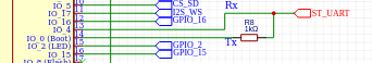
Ryan, can you confirm you are connecting the pullup you’re testing between pin0 and 3.3V?
(from the future):
X,Y,Z Motor Drivers:

On the TMC, these connect to PDN_UART:
![]()
The A,B,C drivers connect to ST_UART after the multiplexer. They are only connected to ST_UART when A_CS, B_CS, C_CS are enabled. Those pins are on the I2S Outputs:

I assume those get connected one at a time, after the X,Y,Z has been configured.
In the jackpot config, the tmc_2209: addr are set to these:
x: 0
y: 1
z: 2
a: 3
b: 3
c: 3
Those addresses are controlled by hard wired lines on the MS1/MS2 pins.
FuildNC must be sending configuration parameters to address 0, 1, 2, and then toggling the multiplexer to send configs to 3, 3, 3 for A, B, C.
I did find a board with 4x TMC drivers and there is no multiplexer. That makes sense, since the TMC drivers can only have 4 addresses.
GPIO16 (which is often used instead of pin0 for tx):
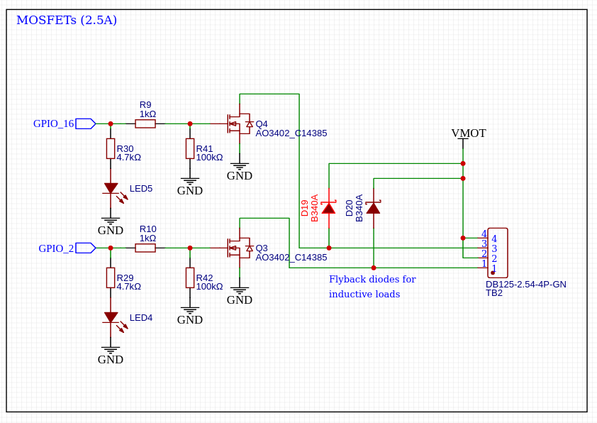
You can’t/shouldn’t use boot0 for that. You don’t want a pull up on the mosfets. Unless you chose a different mosfet that was off when the input was high.
1 Like
Ah, so the 55gal drum of Astroglide I ordered for you is finally there…
3 Likes
Those go to the IO expander chips. 74AHCT595PW,118. It looks like it goes to three of them on the same 3x pins (22,21,17).
Tx0/Rx0 are probably connected to the USB’s UART. That is where the grbl command traffic lives. You don’t want the TMCs there.
1 Like
Yes sir
Well the shipment will make my life my smoother, but I am pretty sure it is something else.
2 Likes
Yes, we did have options but I did not want a clone axis.
I think your design is good. I was trying to answer the question, “Why are ABC on the multiplexer?”. It’s because there are only 4x TMC addresses.
1 Like
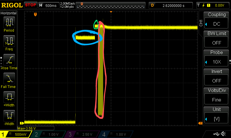
I think I can explain this now.
Pre boot (Blue)
In the blue region (I will call it pre-bopt), all the pins on the TMCs, the multiplexer, and pins 4/0 on the ESP are floating. This voltage is determined by the Pull up, combined with the 3x TMC pull downs (3 in parallel at 20kOhm is 6.7kOhm effectively).
Boot (Green)
In the green region, the esp has booted and turned on a software UART on pins 0 and 4. Pin 0 is now and idle serial, so it is sourcing that signal with 3.3V.
UART (Red)
In the red region, the UART is happening, which we already guessed.
Pull Up Math
This is my bad drawing of ST_UART:
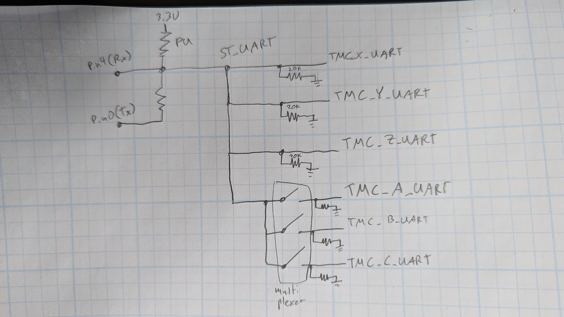
If all those pins are floating, then it gets simplified to this:
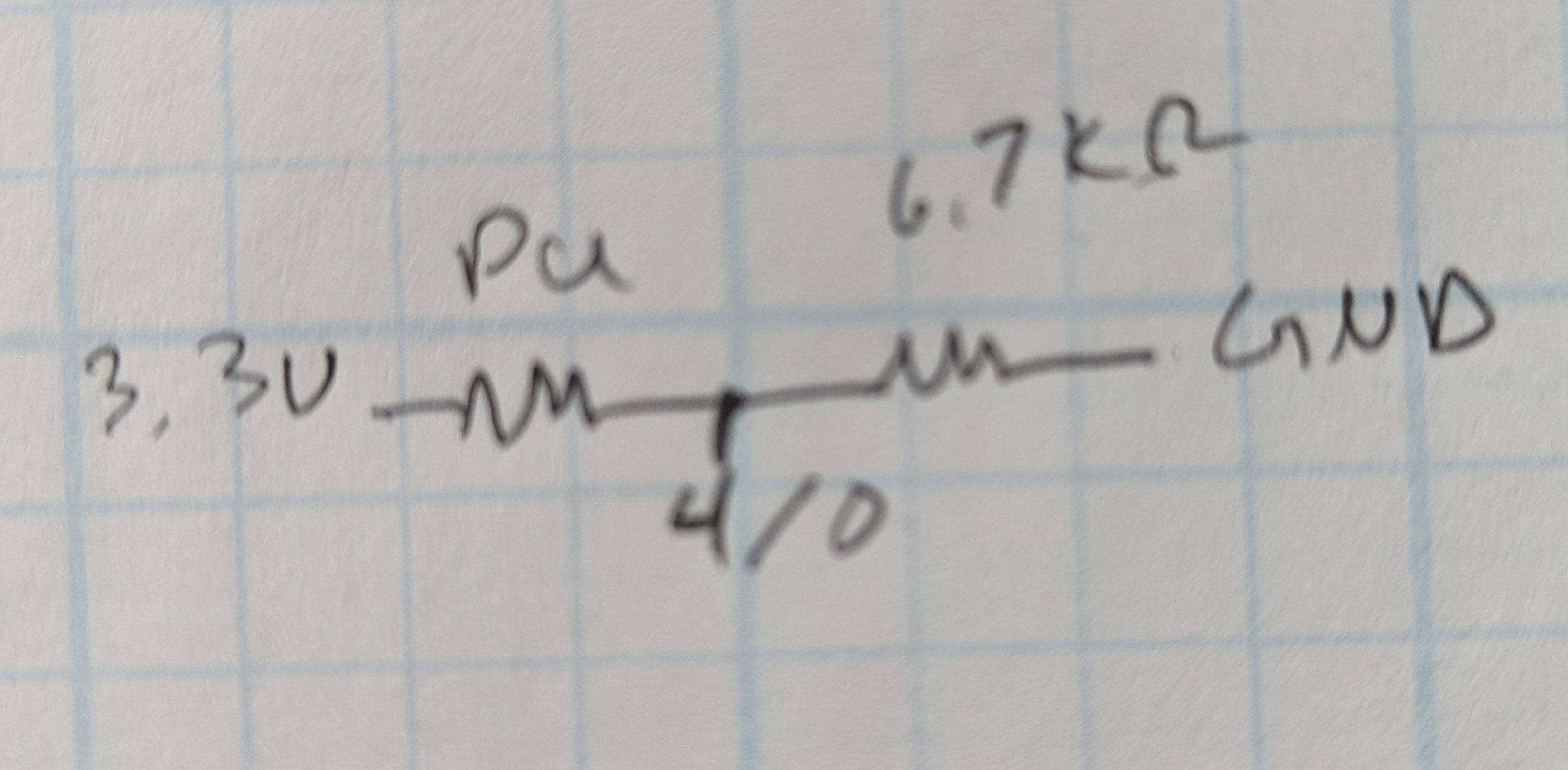
The voltage in that pre-boot region should be: V0 = 3.3V * (6.7/(Rpu + 6.7))
Plugging in 1k, 2k, and 4.8k for Rpu, I get:
1k: 2.9V
2k: 2.5V
4.86k: 1.9V
If I look at the voltages in this post:
It looks more like this:
1k: 3.1V
2k: 3.0V
4.86k: 2.8V
So there must be a pull up on the ESP32 board already. Maybe it is the 10k’s on the DTR/RTS. I plugged that in and the computed values were still too low. It looked like it fit more like a 1kOhm resistor already on the geniune ESP32.
2 Likes
The esp
*edit…this is what should be there (spec sheet for the genuine). Maybe these are what vary between them?
I can check again and read the actual values. I think the ones I wrote down were just kinda guesses. I didn’t have the zero set very well.
Here are some more clues:
The green is still the boot phase. The purple is after the ESP has said something, and one of the TMCs has started a reply. The voltage on pin4 is a bit lower than pin 0 during boot, because pin 4 is floating and pin 0 is high (idle uart).
I think this means that during boot, the TMC UART pins (PDN_UART) are floating. When one of the TMCs wants to respond, it goes to Tx idle, bringing ST_UART up to 3.3V.
I bet further to the right, they all go back to idle and it looks like the green boot region again. I could also guess this happens a few times per driver, or once per driver (the ones in the config file only).
There are two more cases here:
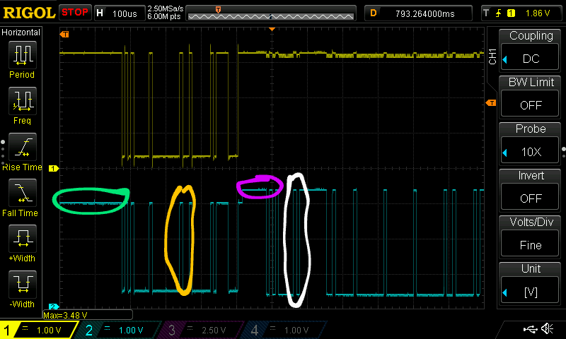
Pin 0 Talks (Yellow)
In the yellow region, ESP pin 0 is sending uart and the other uarts are floating. In this region, the pull up is still pulling up. The TMC are pulling down, and R8 is either pulling down or up, depending on the bytes in the uart.
If you make R8 smaller, the high/low on pin4, in this yellow region would get wider. Pin4 is also what the TMC drivers are seeing. So that is good motivation to not make R8 too large. This picture is from a test with R8 at 1kOhm. It looks pretty good to me, so I would leave it there.
TMC Talks (White)
When the TMC gets enabled, pin 0 is high. so pin 4 is being pulled up by the new pullup, pulled down by the TMC pull downs, and being pulled up by R8 because of pin 0 being idle. The TMC is trying to send high or low depending on the bytes. It looks pretty strong. It should be, because the TMC driver is connected directly to the pin4 (Rx). The other resistors are sinking some current, but that direct connection should make that voltage pretty good.
1 Like
yup exactly.
gotcha
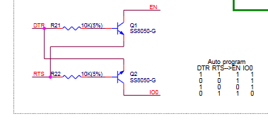
Yeah. I don’t know what is going on there. Those 10kOhm resistors shouldn’t be affecting the boot pin. The Q1 and Q2 could, but I assume they are off. There must be something else pulling these up. Maybe the EN has a 1k pullup?
I got the “actual” values from eye balling the silly scope images. They are far enough from theoretical that there must be another pullup somewhere. It makes some sense. You want the esp to boot when it isn’t connected to anything.
I think we are circling around a 4.7kOhm or so for the pull up between 3.3V and BOOT0. And leaving R8 at 1kOhm. The nice thing about this solution is it is an easy workaround and a simple update to the jackpot.
The boot pin during pre-boot looks reasonable and we can mostly explain the voltage.
When the UART is idle (or during “boot”), the voltage on pin 0 and pin 4 makes sense to me.
When the ESP is sending, the TMC Rx is getting strong high/low signals (yellow). When the TMC is sending, the ESP pin 4 is getting good signals (white).
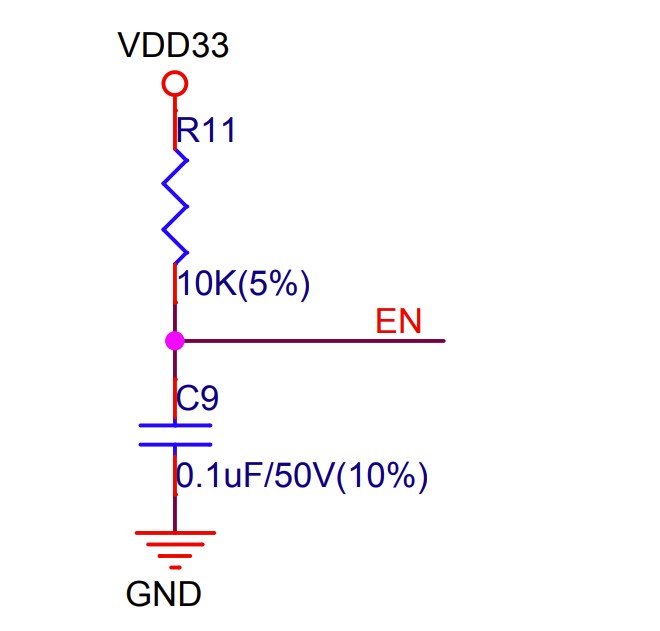
The only case that we haven’t seen is when flashing. Something @MakerJim suggested we confirm. When the DTR/RTS do their dance for resetting the chip, they are going to be yanking that boot pin around. Can you get a scope of what that looks like? If you want extra credit, also scope the EN pin. I expect pin 0 to be high before anything happens, and when you start the flash, it should go low. Hopefully it goes very low. IDK what it will do once the flashing starts. It might just stay low the whole time.
Once it is finished, it should go high again. When the board is reset.
1 Like
Shouldnt you be able to listen with something like putty, or no? I amnot familiar with uart
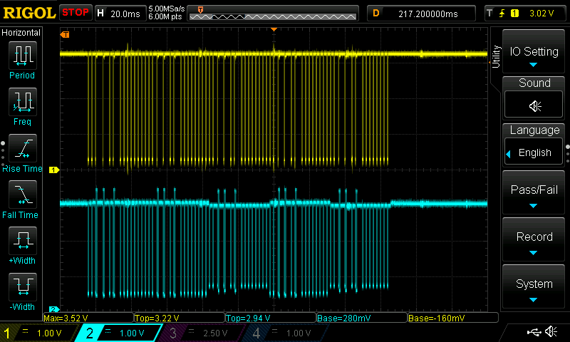
This is very neat. You can see in the blue pin 4 where there are 5x there are 3 higher sections. At each of those places, the yellow has a small blip of noise under the max.
Those must be each of the 5 drivers getting configured. I bet it is: X, Y, A, Z, B. I will have to think about why A and B have slightly smaller signals. I guess it is more pull downs, but why would the bottoms be higher too?
NICE. I can wire this up and test with all the bords I have to verify the pre-boot stays high enough.
Yup I can try catching that.
I have that in the early shots. It is high just before everything else, tiny bit.