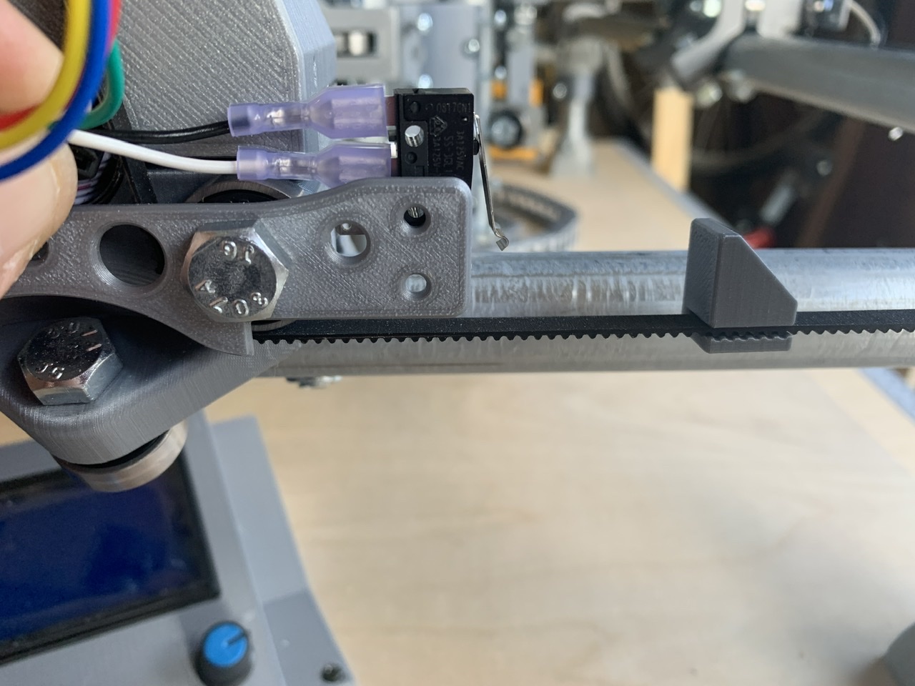
What am I missing? I printed the dual end plate brackets for the MPCNC from this site, and received the switches from the pre-assembled kit.
If I hook up the wires and switches as they come, the back end of the female spade connectors will 100% be pressed against the bearing. Do y’all usually trim down the male spade and solder the wire?
Additionally, what is the exact measurement from (X0,Y0) for the printed bump plate? I couldn’t find that info on V1 anywhere
Apologies for the limited pictures. New users are limited to 1
I haven’t installed the end stops on my build yet (I use hard stops for now) but I imagine the measurement will differ slightly for each build since each machine is unique. I would set them so there is a small gap between anything on the x or y axis that may crash at the travel limit. If your build is square the other side of the same axis would go the same distance away. Once you have them setup I believe there are instructions to adjust as necessary or just draw as big of a square as possible and post the results here.
I did this on mine too. The stops on the belts might be ok but I wasn’t comfortable with it. There are several endstop blocks on thingiverse, this was the one i used: MPCNC end stop block by thingsdavemade - Thingiverse