I figured I’d start a build thread for posterity, though I suppose it’s not that unique of a build. Maybe for keeping my own sanity through social interaction is a good enough reason ![]()
I’m a newbie to CNC I suppose. So excited about diving in and working through it. I can probably come up with a dozen projects I’d like to do, but the imminent need is for cutting foam to create male plugs for composite molds. I am building a 2012 BMW 128i with all the basics (big stroker LS, 6 speed, giant tires all the way around). A sort of do-everything set up. I needed to build the flares for the fenders, do not like what is for sale, and so am going down the sadistic path of doing my own. I could just mock up foam on the car and pull from that, but I needed a CNC anyway right? So here we are. Flares are prototyped in Rhino from a 3D scan I made of the fenders. Now on to the CNC part…
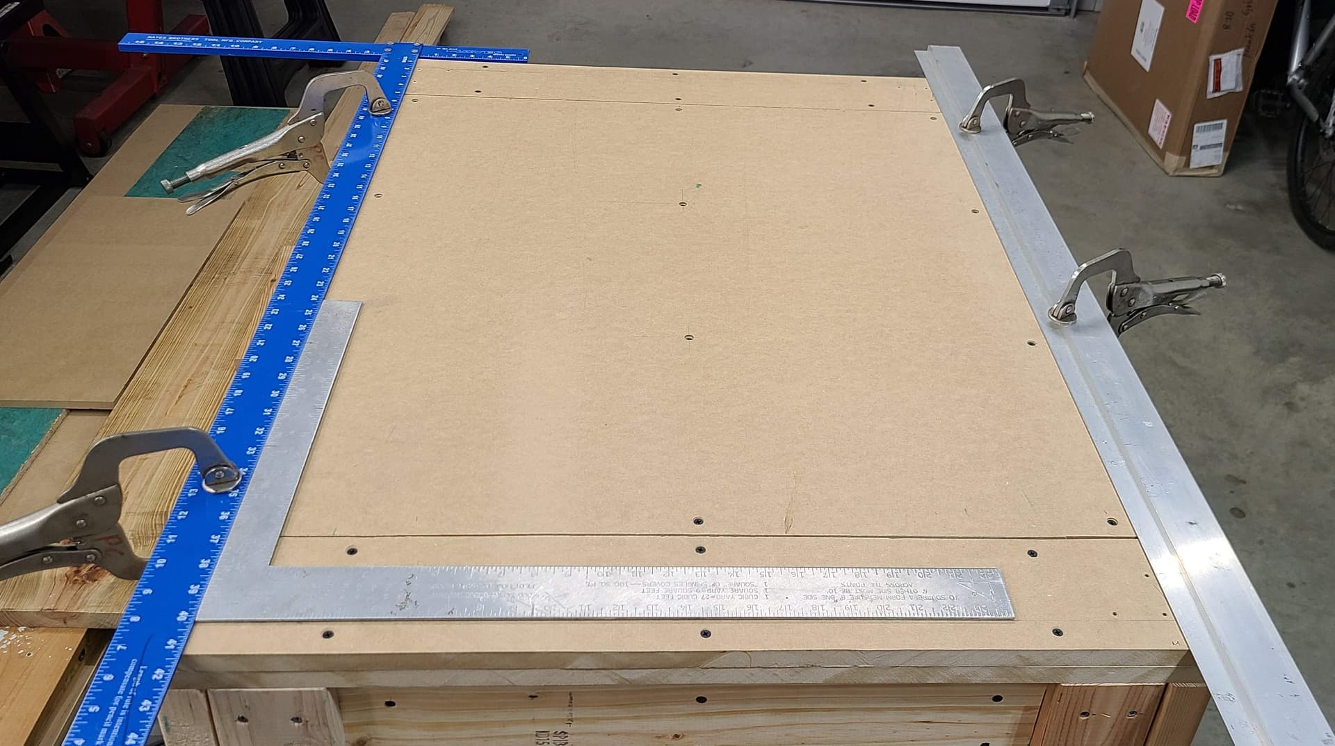
Build volume will be 28"x18" X and Y. Z clearance may be set a little higher than ideal while I do the foam project (haven’t decided but likely 5"), then shortened after for future projects. Build volume was a compromise of fitting the thing in a specific place in my garage, knowing I could go smaller later, and figuring what size I wanted to make the foam slabs that will be individually cut and fit together to form the male plug.
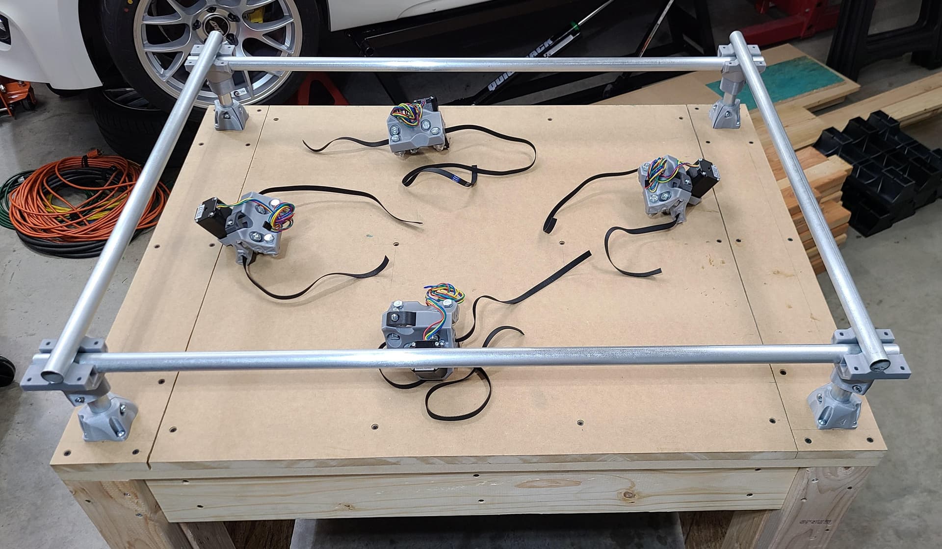
3/4 EMT conduit. I’ve received all the hardware from V1 and new Makita router so ready on that front as well.
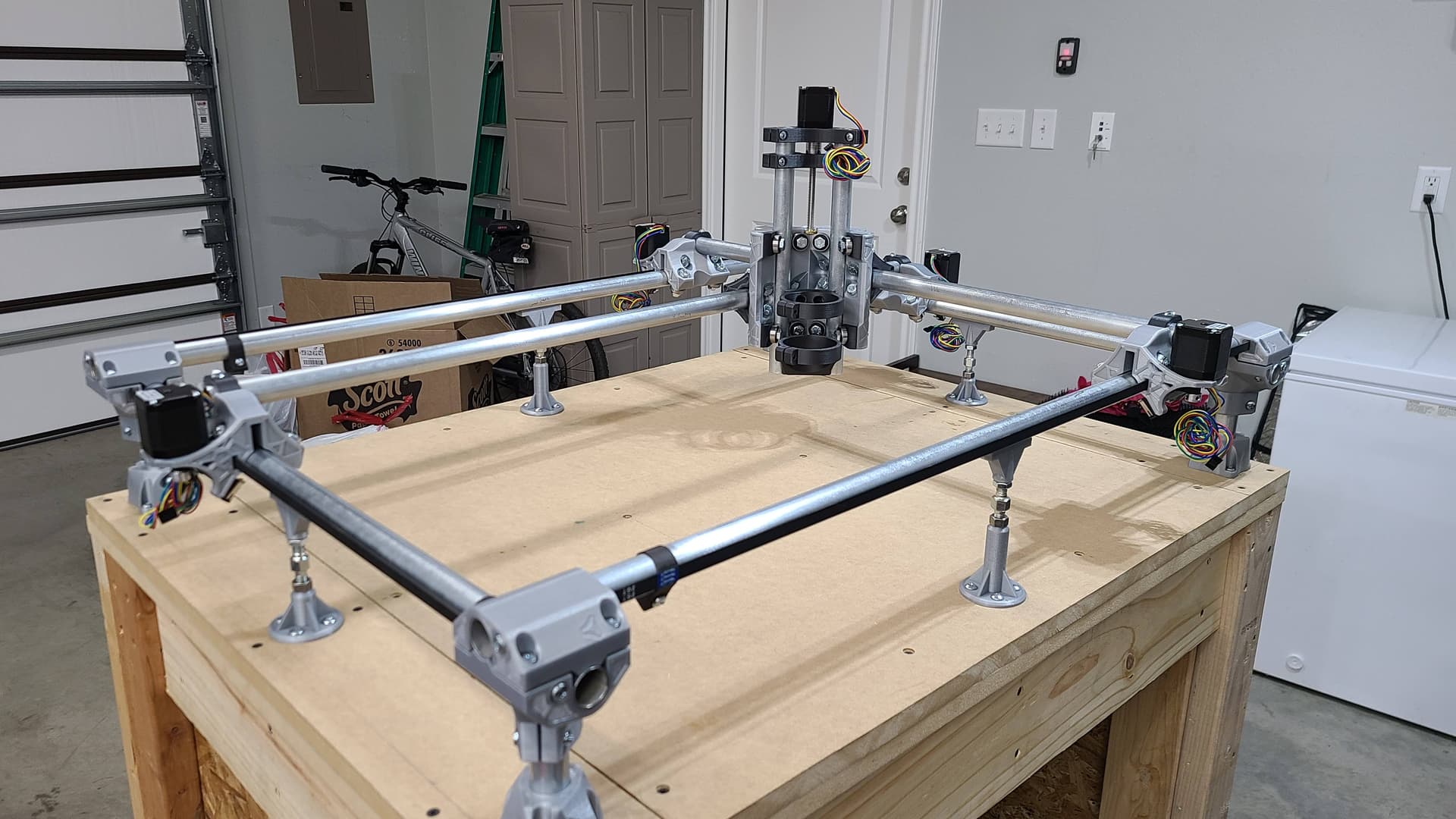
Finally finished printing the actual MPCNC pieces. Still have to print electronics enclosures and dust collection. Still gotta remove the brim from a few pieces (prints take too long not to include a brim IMO)
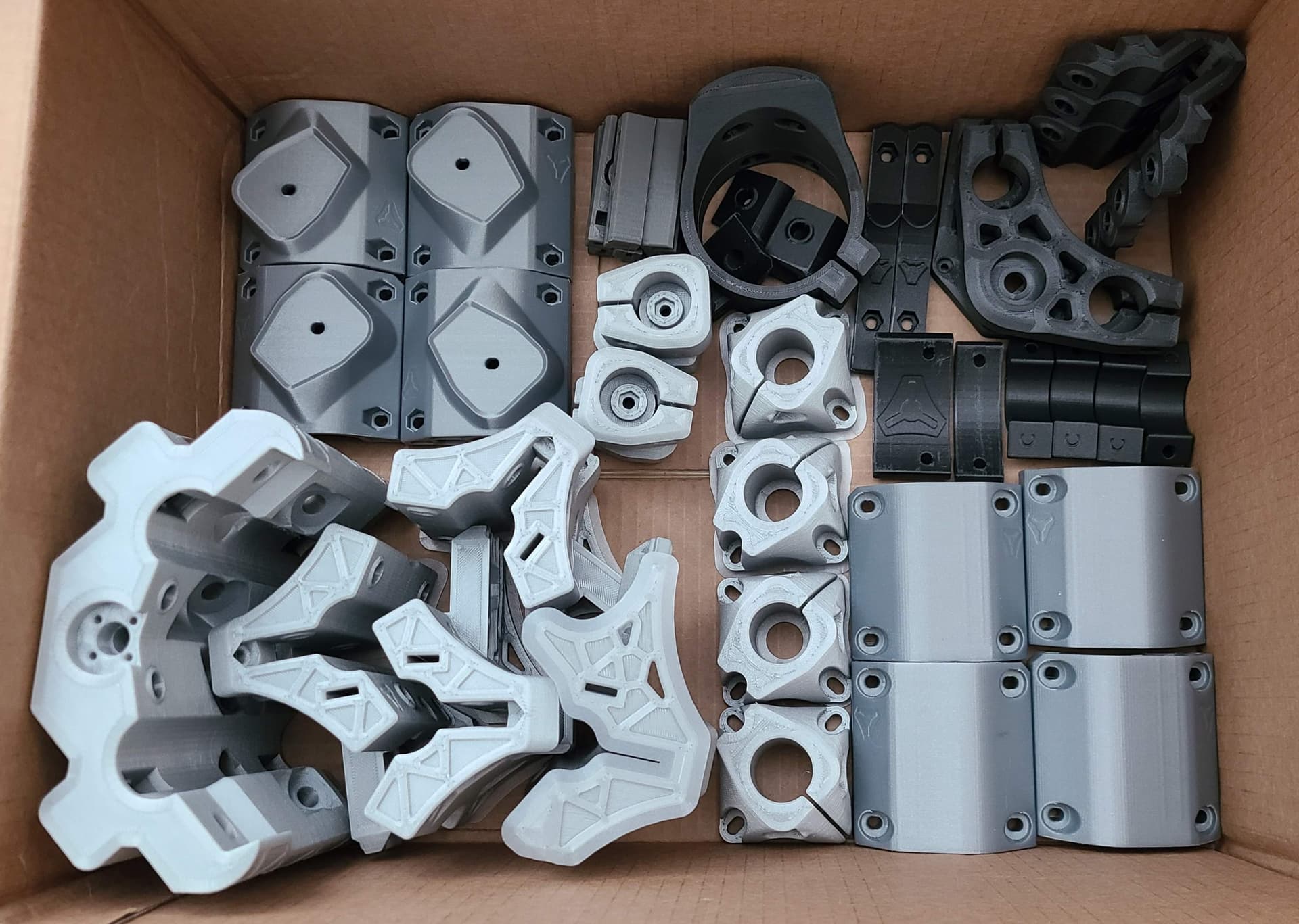
Did most with 6 perimeters, 8 layers top and bottom. Bumped it to 8/10 for the feet. Set to .30 layer height on an .40 nozzle.
Coming off the filament comparison post I made, I’ll share my filament choices. (The complete ones are marked, the rest is to be soon and may change my mind before they print ![]() )
)
| QTY | Part Name | # completed | Infill | Filament |
|---|---|---|---|---|
| Corner | ||||
| 2 | Corner Bottom | 2 | 50% | Atomic PLA Metallic Silver |
| 2 | Corner Bottom Mirrored | 2 | 50% | Atomic PLA Metallic Silver |
| 2 | Corner Top | 2 | 50% | Atomic PLA Metallic Silver |
| 2 | Corner Top Mirrored | 2 | 50% | Atomic PLA Metallic Silver |
| 2 | Lower Belt | 2 | 50% | Sunlu PLA Grey |
| 2 | Lower Belt Mirrored | 2 | 50% | Sunlu PLA Grey |
| 2 | Upper Belt | 2 | 50% | Sunlu PLA Grey |
| 2 | Upper Belt Mirrored | 2 | 50% | Sunlu PLA Grey |
| 2 | Wire Darryl | 25% | Atomic Orange PETG | |
| 4 | Stop Block (Dual only) | 25% | Atomic Orange PETG | |
| 4 | Corner Leg Lock | 4 | 50% | Atomic PLA Metallic Silver |
| 4 | Feet | 4 | 50% | Atomic PLA Metallic Silver |
| Trucks | ||||
| 2 | Truck | 2 | 50% | Atomic PLA Metallic Silver |
| 2 | Truck Mirrored | 2 | 50% | Atomic PLA Metallic Silver |
| 4 | Truck Clamp | 4 | 50% | Prusa CF PC Blend |
| Z-Axis | ||||
| 1 | Z Motor | 1 | 50% | Prusa CF PC Blend |
| 1 | Z Coupler | 1 | 50% | Prusa CF PC Blend |
| 2 | Nut Trap | 2 | 50% | Prusa CF PC Blend |
| 1 | Upper Tool Plate | 1 | 50% | Prusa CF PC Blend |
| 1 | Lower Tool Plate | 1 | 50% | Prusa CF PC Blend |
| Dust Collection | ||||
| 1 | Dust Boot Inner V2a | 25% | Atomic Orange PETG | |
| 1 | Dust Boot Outer V2 Thin | 25% | Atomic Orange PETG | |
| 1 | Dust Boot Outer V3 | 25% | Atomic Orange PETG | |
| 1 | Dust Top V3 | 25% | Atomic Orange PETG | |
| 1 | Main Body V3 | 50% | Prusa CF PC Blend | |
| Tool Mounts | ||||
| 1 | Makita Top | 1 | 40% | Prusa CF PC Blend |
| 1 | Makita Bottom | 1 | 40% | Prusa CF PC Blend |
| 1 | Makita Tramming Tool | 25% | Atomic PLA Metallic Silver | |
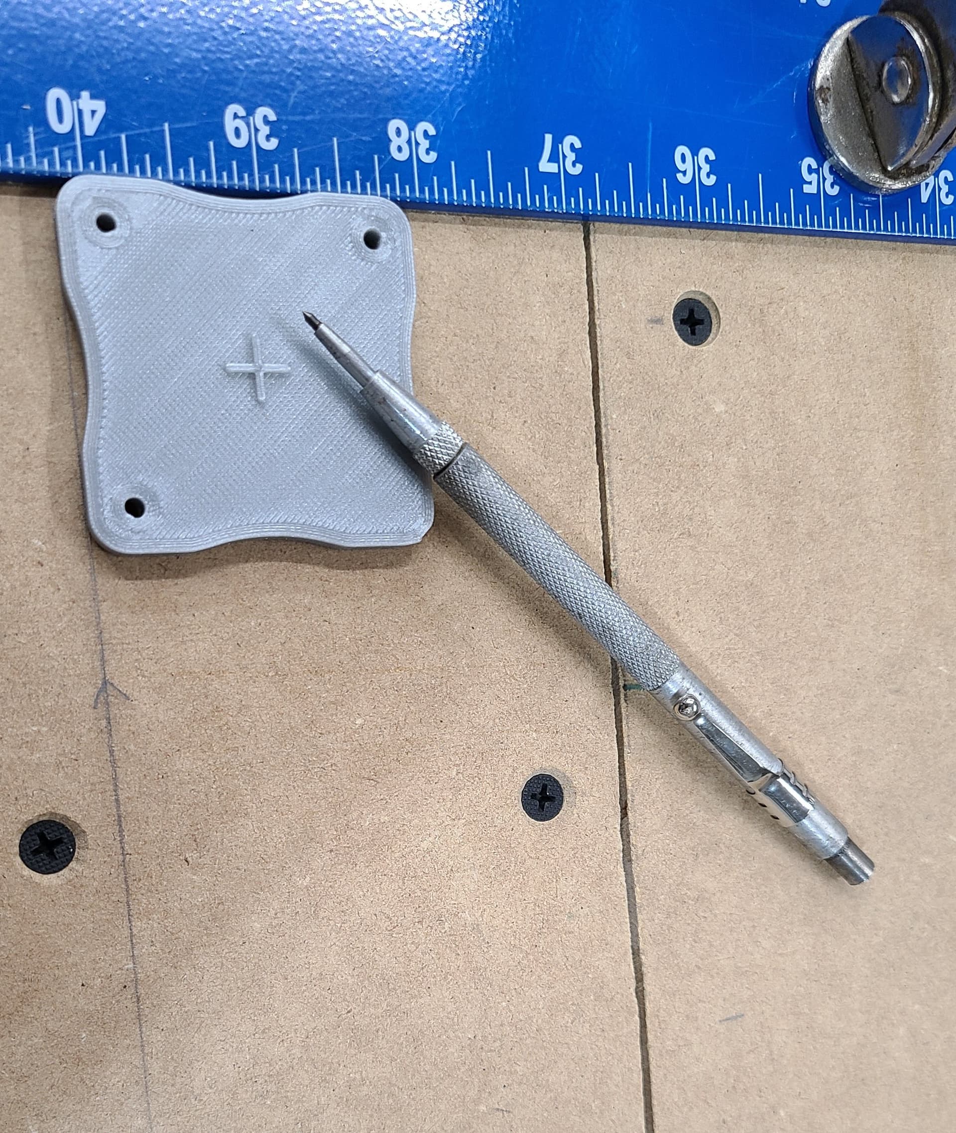
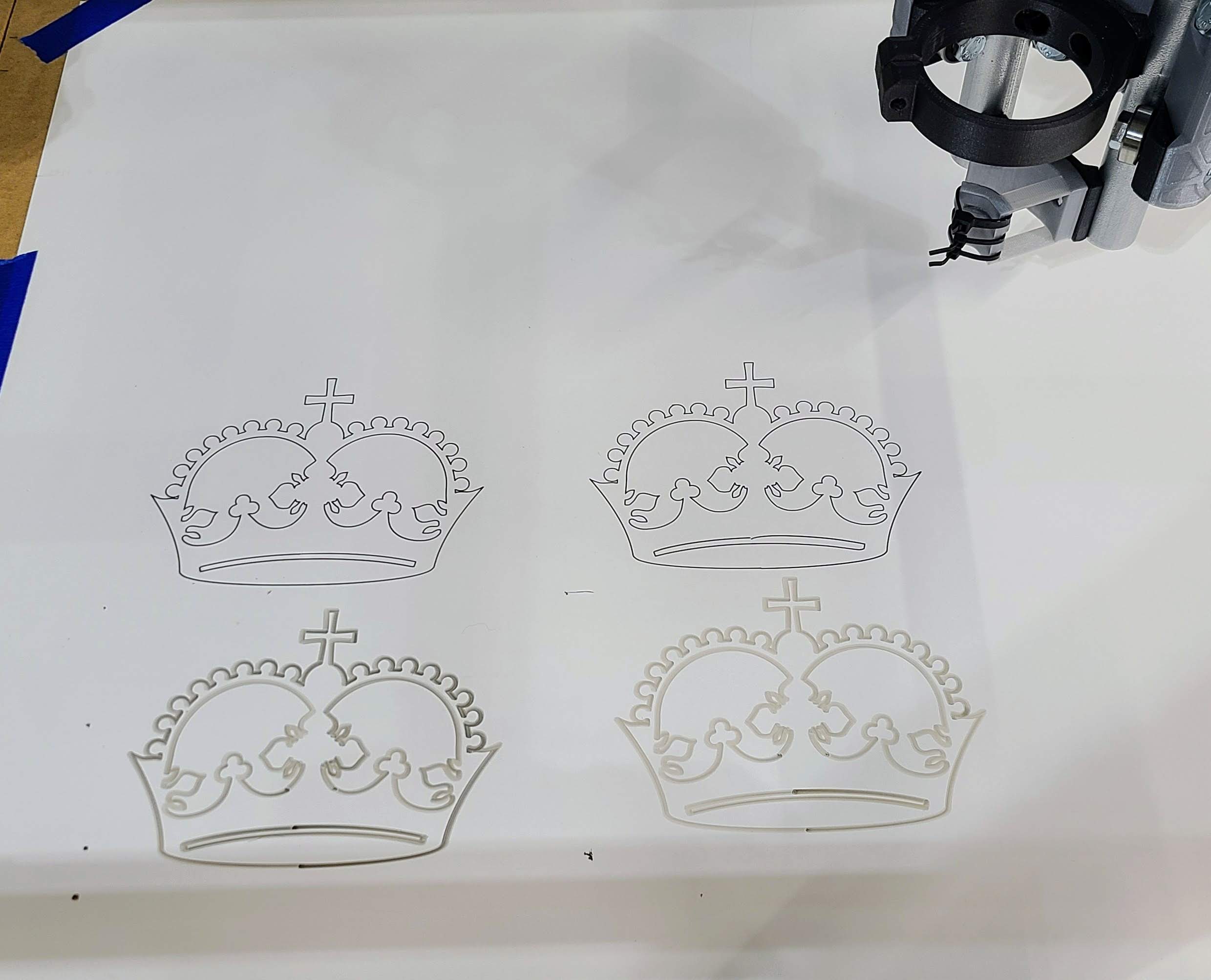
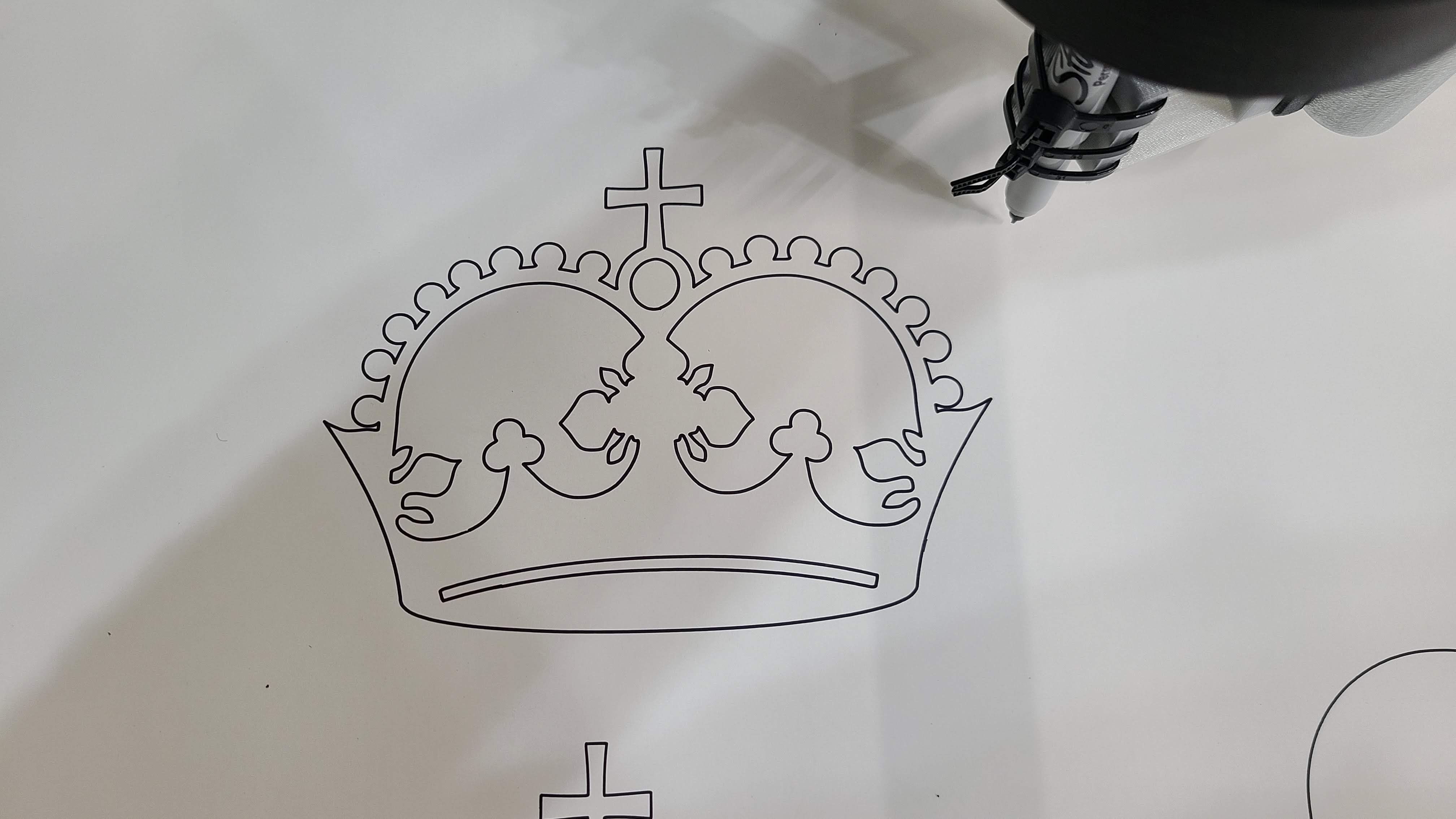
| 1 | Knife Pen Mount | 50% | Atomic PLA Metallic Silver | |
| 1 | Pen Holder | 50% | Atomic PLA Metallic Silver | |
| Center Assembly | ||||
| 2 | Core Z Clamp 1 | 2 | 50% | Prusa CF PC Blend |
| 2 | Core Z Clamp 2 | 2 | 50% | Prusa CF PC Blend |
| 3 | Core Clamp | 3 | 50% | Prusa CF PC Blend |
| 1 | Core ClampY | 1 | 50% | Prusa CF PC Blend |
| 1 | Core | 1 | 70% | Atomic PLA Metallic Silver |
| Electronics Cases | ||||
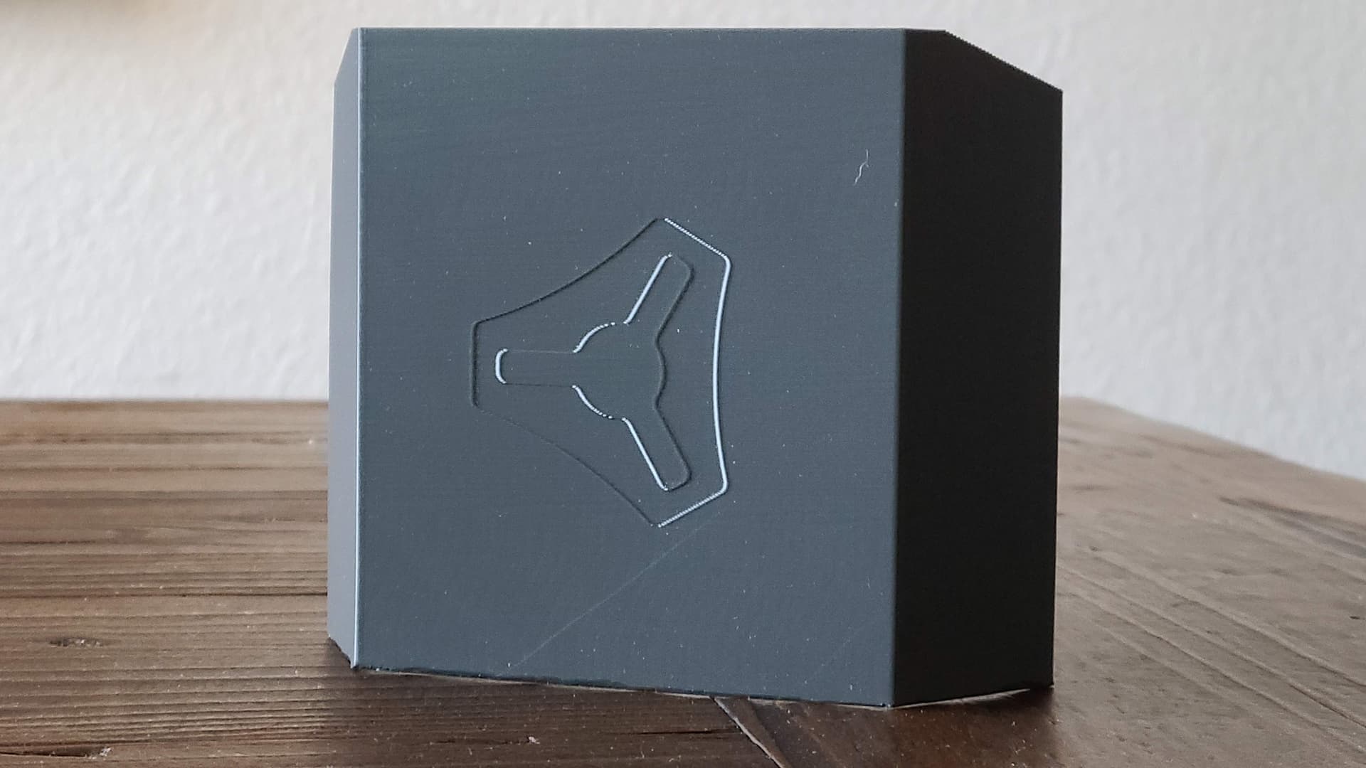
| 1 | Gnarly Base | 25% | Atomic Black CF PETG | |
| 1 | Gnarly Pass Through Lid | 25% | Atomic Orange PETG | |
| 1 | Gnarly Plain | 25% | Atomic Black CF PETG | |
| 1 | LCD Body | 25% | Atomic Black CF PETG | |
| 1 | LCD Clip | 25% | Atomic Orange PETG | |
| 1 | LCD Right | 25% | Atomic Orange PETG | |
| 1 | LCD Left | 25% | Atomic Orange PETG |
Atomic PLA did very well on the test, and I like the metallic silver (sort of looks like aluminum if you close one eye and look sideways at it). So I chose it for most things. I used the Prusa CF PC Blend for some of the mounting pieces. I may reprint some of the other pieces in this later, but PLA will work great for now.
Making a jig to hold the EMT and I’ll probably cut it on my SWAG band saw. I’ve shimmed it to be almost perfectly square but if I’m not happy, I’ll try my metal chop saw.
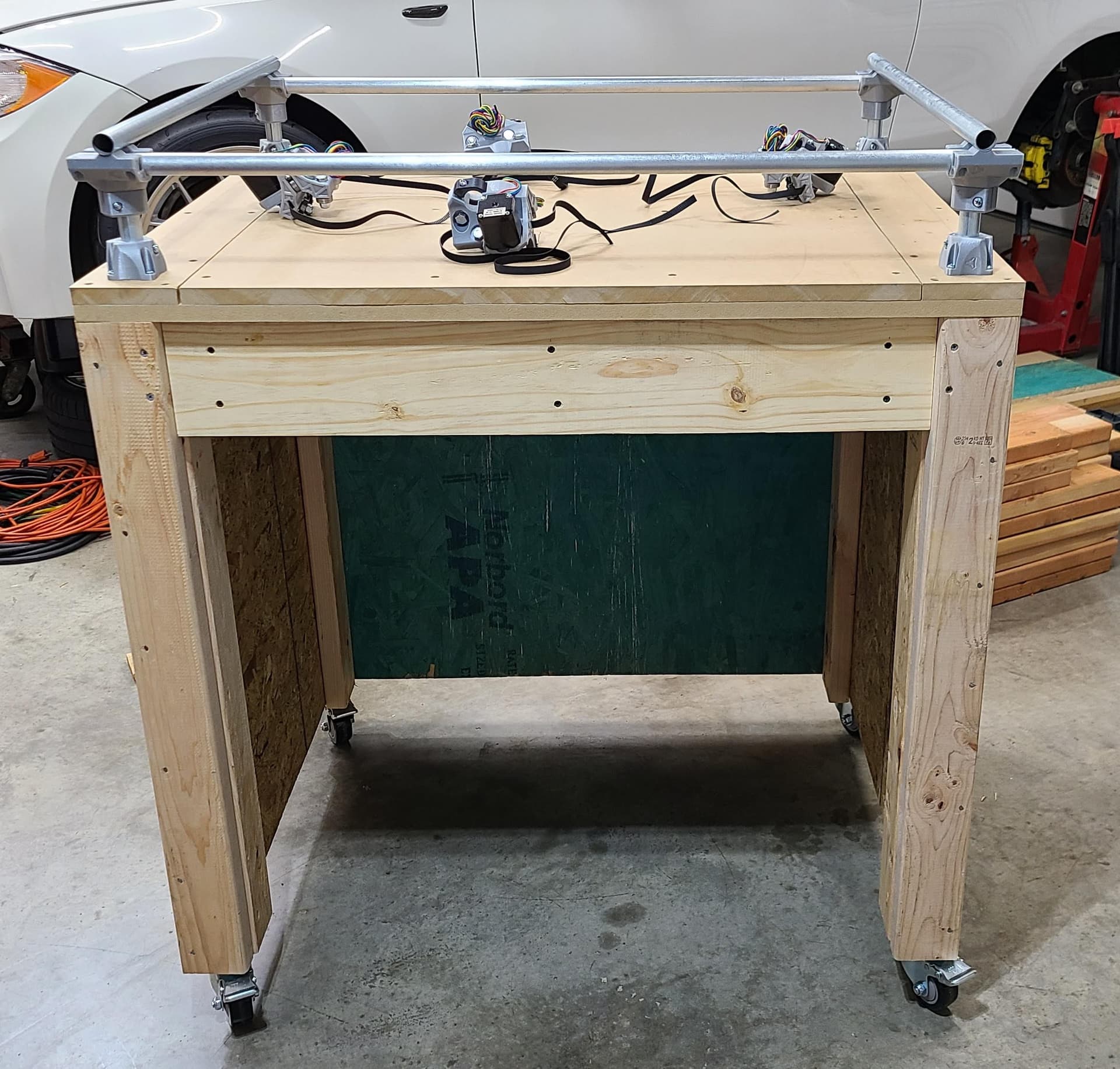
Hoping to start on the bench this weekend. I mocked it up in Fusion360. (there are casters on the toolbox…sorry for the omission)
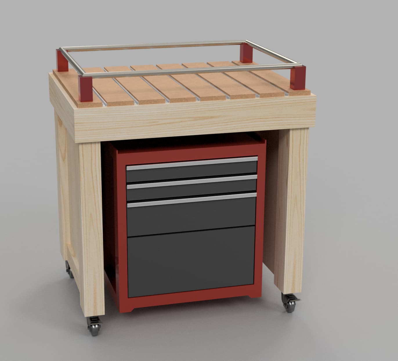
Top is semi-torsion box I guess. 1x4 frame with 1/2 plywood on top and bottom, 3/4 MDF on top of the “box” for the base. Then the MDF strips and T-track on top of that. 2x4 legs, 1/2 plywood sides and back. 1x6 wrap around the top perimeter.

Anyway, I’ll post as it goes along. Big thank you to Ryan for making this a possibility for us all.
 Those threads are a lot of fun, also a dump for you to remember how far you’ve come. I like to go back through mine and enjoy the memories.