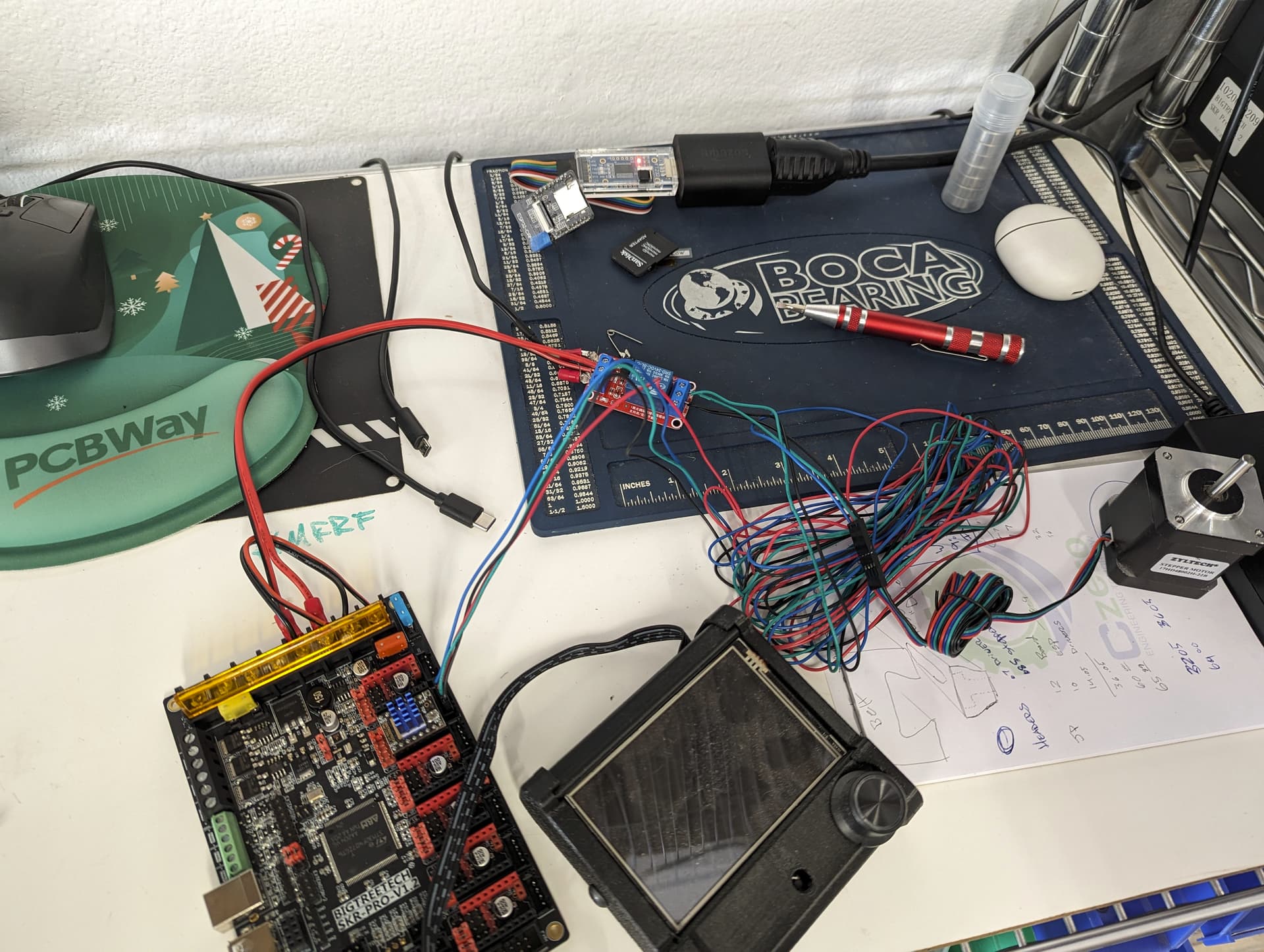
They work perfectly. I feel no hesitation to engage as a brake and it opens before the board boots, steppers works as expected. I can check anything you think I might have missed.
So now can we use this and make it better. @Michael_Melancon had the another idea. How about a tiny NC SSR. This is NO, but shows the size.
@jono035 Do you have input here? If the relay works and we can find a tiny NC SSR will we be able to use it just the same? Think we can make it for under $3.25 each?
How do you have it hooked up at the moment? Are there relay contacts on both coils of the stepper or just one? Both coils would be the obvious one, but it may be possible to do it just with a single coil.
Just so I’m understanding this correctly as this isn’t an issue I’m personally familiar with: There are 2 similar goals here, right? One is to stop the bed hitting hard stops at speed, the other is to avoid an over-voltage on the stepper driver boards? The relay is doing this by providing a braking effect to slow the drop of a print bed that’s being entirely held up by stepper torque?
Are you able to take a reasonable guess at how much current is actually flowing in those coils under a realistic drop scenario and how long it would take? Hooking up a shunt (could just be a 1 ohm resistor) in line with the relay contacts and looking at it with a scope during the drop would be pretty fascinating.
Assuming I’ve got that correct, I can think of a bunch of ways to doing that. I think Mike is thinking along the same lines that I am with respect to the SSR. Just as a point of clarification, an SSR is usually an entire circuit that is intended to mimic the functions of a relay (isolated control inputs at moderate DC voltages, AC or DC load control etc.). I’d envisage it more as a circuit that’s using a FET to short the coils when on.
There are a bunch of ways to do this, off the top of my head.
The easiest would be to choose a device that’s normally on (equivalent to normally closed contacts). Junction FETs are perfect for something like this but they’re a slightly oddball part that don’t really get made as power devices. Max rating I can find for conventional parts is 50mA, although given that this is a short term thing we could likely exceed that significantly. Another option would be depletion mode MOSFETs. They’re basically just an ‘inverted’ version of a regular MOSFET where they’re normally on and applying a voltage turns them off (depletes the carriers that cause current flow, hence the name). They’re also a bit of an oddball part but are more common than junction FETs. They have the downside of having a body diode still so you’d need 2 of them back to back to create an AC switch.
The second way would be to use regular MOSFETs and some extra circuitry around them as they would be normally off and need voltage to turn on. This voltage could be from the printer power supply and then just have enough capacitance to turn the MOSFETs on and keep them on for a few seconds after a power failure. That would only work for a power failure, not for someone lifting and dropping the bed, though. Another way would be to use the voltage across the stepper coils themselves which would add a tiny amount of load to the stepper drivers but potentially allow the circuit to function from an unpowered start. It might drop a little bit, power up and then activate the FETs.
There are also options using triacs and all sorts of funky things that spring to mind.
Some other thoughts:
Would it be valuable to have the circuit able to be accidentally engaged without frying the stepper drivers? A dead short might kill them where a couple of ohms of load might not? Does a dead short kill them?
Would this be something that needs to be entirely standalone and automatic, or could it be controlled by the controller, such that there’s a ‘disable brakes’ line or equivalent?
How good of a handle do we have on what the criteria are for triggering the brake? I guess as long as Vmot is still available, the drivers are engaged? Is there a separate driver enable line that could be watched to trigger the brake?
Tough to say and would entirely depend on volume, connector types etc. Is $3.25 the cost per motor or total per system? My gut feel is ‘probably’, but I think the real value would be if it could be made better or less likely to hurt things than a simpler relay based system.
At the moment, that’s the cost for one of those relays, which I think we need 1 per motor.
The Relay is just a Normally closed mechanical relay.
I’m not sure which configuration Ryan tested so far, but the idea is, anytime the motor is getting power, the relay opens, and lets it function normally.
Any time power is lost, which is the condition that allows the build plate to drop, the relay would close and short the coil, causing it to at least drop much, much slower.
I looked around a bit to try to find some cheap NC SSRs, but didn’t have much luck.
In my opinion, our best bet would be if we can wire it inline with the motor power so that it catches all possible situations where the motor drops, not just complete power failure (Klipper config save, etc.)
Even better, if it could be made as a small PCB that can be added near the board, then it’s a really easy brake to integrate.
So I’m not sure the best way to accomplish it, but the goal would be to do the same as we are doing with the mechanical relay, in smaller form factor, non-mechanical parts.
Bonus points if we can also add flyback protection to that board in the failure case of the thing we are using to try to prevent failures, so no more SKRs go up in flames
Yeah, I think by heading into SSR territory things will always be getting a bit weird and likely on the more expensive end of the spectrum, too. This would essentially be developing a special-purpose SSR.
Right, so either a 1-stepper-per-board design that could go right next to the stepper or a 3/4-steppers-per-board design that went next to the controller or at some other convenient distribution/split point? I gather the potentially 3/4 steppers would be individually controlled for bed tilt control, so would all be individually wired anyway?
Do you mean the motor power as in output from the stepper drivers or as in Vmot power? I can definitely see what you mean from the perspective of detecting the stepper current stopping. That may be a little more complex to sense than a nice clean enable line disappearing or a power supply voltage dropping.
Yeah, that’s what I was getting at when asking about whether it was just preventing a drop or also the over-volt. It would be super easy to make a design that clamps using cheap FETs for ~10 seconds after a power failure, but a bit of extra work might be needed to fulfill that goal.
I’d love to know a max current that we’d need to worry about. I’m just trying to think about how to test that… Multimeter in AC current mode wired in series with the stepper coil, pulley on the stepper, wrap some string around it and try to spin it using 1kg/2lb of pull?
Trying to think about what the simplest solution would be for making it, just to ballpark costs etc.
The simplest would be board that has a power supply wired to it and 2x N-channel FETs with maybe an op-amp or comparator that pulls the gates high whenever the power supply goes away.
2x 5c FETs,
1x 30c op-amp
1x decently large capacitor
1x diode
Half a dozen passives
50c connectors?
Maybe $1?
Downside being that it would need a separate power line run out to it and it probably wouldn’t prevent over-voltage if a gantry was moved or whatever.
I can’t seem to get a current reading, maybe my meter is too slow. Getting a voltage is hit or miss as well, slow meter is clearly a bit behind the peak.
I did find that at least using only one coil it eventually lets go. As in it only holds so much before it “slips”. Let me try to figure that out.
I am going to need coffee in my system to start understanding that. Thanks Jono! I /we will surely need to dig into that further. Before I when know where to go from there.
You’ve already touched on much of what I noted earlier.
Some of what I was spitballing-
The enable is really fast on the driver. You don’t really want the driver to see a shorted motor coil, so have to think through what happens in the system when the drivers may be on or off. It may be sufficient to present something like a 1 ohm load to the stepper, but now you’re into power resistors that won’t be as cheap as a wire shunt.
I don’t think the way you’ve wired the relay is sufficient- by wiring VMOT power do an NC relay, you open up the shorting path on the relay when power is applied to the board. That’s probably OK. But now consider that as you’re running a print job, many slicers end gcode disables the stepper drivers at the end of a print. If that happens, you now have no way in the system to apply the brake at a time you most need it. You’ll blow up the regulator on an SKR pro as the bed drops.
You really need to apply the brake any time that the controller has VMOT present, and the Z axis stepper drivers do not have their enable asserted for whatever reason. Those are the conditions when the bed will drop. Hard wired relay to VMOT won’t suffice. You also have to be sure that when enable is asserted that the drivers don’t see a dead short.
This is why I said that if you use a relay that you should have firmware assert a GPIO that I’ll call BRAKE_ON for the sake of discussion. The rule would be that you are going to enable the Z stepper that you then disable BREAK_ON with sufficient time for the relay to respond before the firmware then asserts the enable to the Z drivers. Similarly, when firmware is going to turn off the Z enable (like when end of job gcode is going to shut them off), you first turn off the enable, and only then assert BRAKE_ON.
You can get around all this firmware complexity if you use something faster than a relay, but then you have all of the work to design a suitable fast responding circuit that isn’t hideously expensive to build. Certainly doable, but possibly more challenging than just doing the right thing with the printer controller firmware.
Another thing you want to find out, is as mentioned above: do an instrumented set of drop tests to characterize just how bad it is when the stepper is in free fall with a heavy bed. We already know from @Jonathjon experience that his repeat can easily blow the regulator on an SKR pretty much every time he has a bed drop experience (Like say updating klipper firware and having that drop the enable while the board is rebooting when the bed is up at the top of Z travel.)
Edit to add: instead of BRAKE_ON, it may be better to invert the firmware control to be BRAKE_OFF. So, if you crash or reboot the controller and that drops the enable to the Z stepper drivers, you get the brake in effect. It’s an interesting thought exercise.
This is pretty easy to do in klipper. @Michael_Melancon sent me this video on it the other day that explains it real well. And even with the relays being 24v that shouldn’t be a problem. I can use a spare fan or heater pin to run the relay. That will allow it to not drop as soon as power is applied back.
Thinking about this just from a power failure point. sure the break catches it but if its just a quick blip then as soon as the power comes back on your relay is released and the beds falling just as it would without the brake. Does marlin immediately engage the motors on startup? The one printer I have still on marlin doesn’t for sure but its an old version of marlin and things could have changed. I know klipper doesn’t engage them right away.
It was mentioned before in the other thread that the brake had to be off when the drivers powered up or they would go into fault. If this is the case then this brake wont work from what I can see. But if it is not the case then I think its great as long as we power it from the board and not direct from the power supply.
Or when it tries to home but the connection to the X endstop wasn’t secure so it senses a problem and disconnects from the mcu… yeah that happened today. Luckily without the glass on there it didn’t fall as hard and no magic smoke. Connection has been fixed now thankfully.
I guess this also depends on whether it’s something that is generic and can be used without needing anything from the controller, whether it needs a GPIO on the controller and specific firmware adaptations or whether it needs specific hardware on the controller like a newer rev of the Jackpot. Each of those have different considerations in terms of overall cost/complexity.
Maybe not, but a 1W 1R surface mount resistor is likely plenty enough for a short while and a few cents in volume. I can’t see how that’s an issue, personally.
Seems that you’re talking about something solvable in firmware, though? Some slicers disable the steppers but presumably that’s modifiable, or ending the job at the bottom? It’s also possible that we could consider adding a shunt regulator and dump load if overloading SKRs is a primary issue.
That’s exactly what I was getting at above. The trigger doesn’t need to be only one thing, necessarily, but whatever it is it should encompass the situations that may cause issues, particularly ones that aren’t preventable in other ways such as firmware/slicer behaviour.
Not sure, I am fairly certain it does, and is. The relay powers quickly and releases just as quick the skr take a second to power and boot and takes a second to dissipate the power.
Going to be tough to be $3.50 off the shelf works fine.
Easy. Before the disable the steppers step it drives to Z max. We currently already do that.
I do not think there is anything that easy that will always work. If the enable pin is not a constant on would be easy anything else will take firmware edits, not assigning a pin, making sure any motor disable call would have to trigger a pin. All that to be sure the bed is down when you save a file in klipper. Currently, the only other bad thing that can happen in Marlin is a power outage.
That might be easy in klipper but is not needed in Marlin at all. Nothing kills the steppers in marlin other than gocde or power outage so that gcode is always prceeded by the Z max gcode.
If it is easy to do in Klipper we can use the input pin on the relay (until we find something else).
The relay has an input pin I have jumped. If it is easy in klipper to assign a pin, you trust that, and it is fast enough we are fine. In marlin we jus tuse the jumper as I have it.
Unless there is an easy way to make a solid state version we have a good solution. it is cheap and we can add more if needed.
If you are running klipper and the TMC are communicating and show a shorted line I do not think it will work after that. They might power down the stepper but that does not mean they stop talking.
Do we need the brake on at boot? I’m kinda struggling to believe that the braking steppers will actually hold the bed up.
My approach would be handle the on-to-off transition first and then assume that the bed has made its way to the bottom gracefully.
A short brown-out might cause issues where the drivers fire their short circuit protection, but that might be ‘out of scope’?
Alternatively, it doesn’t necessarily need to be a dead short on the steppers, it can present an ohm of load or so, or even an inductive load such that the stepper driver is happy turning on into that load but the brakes engaged will limit maximum performance of the stepper rather than fault anything.