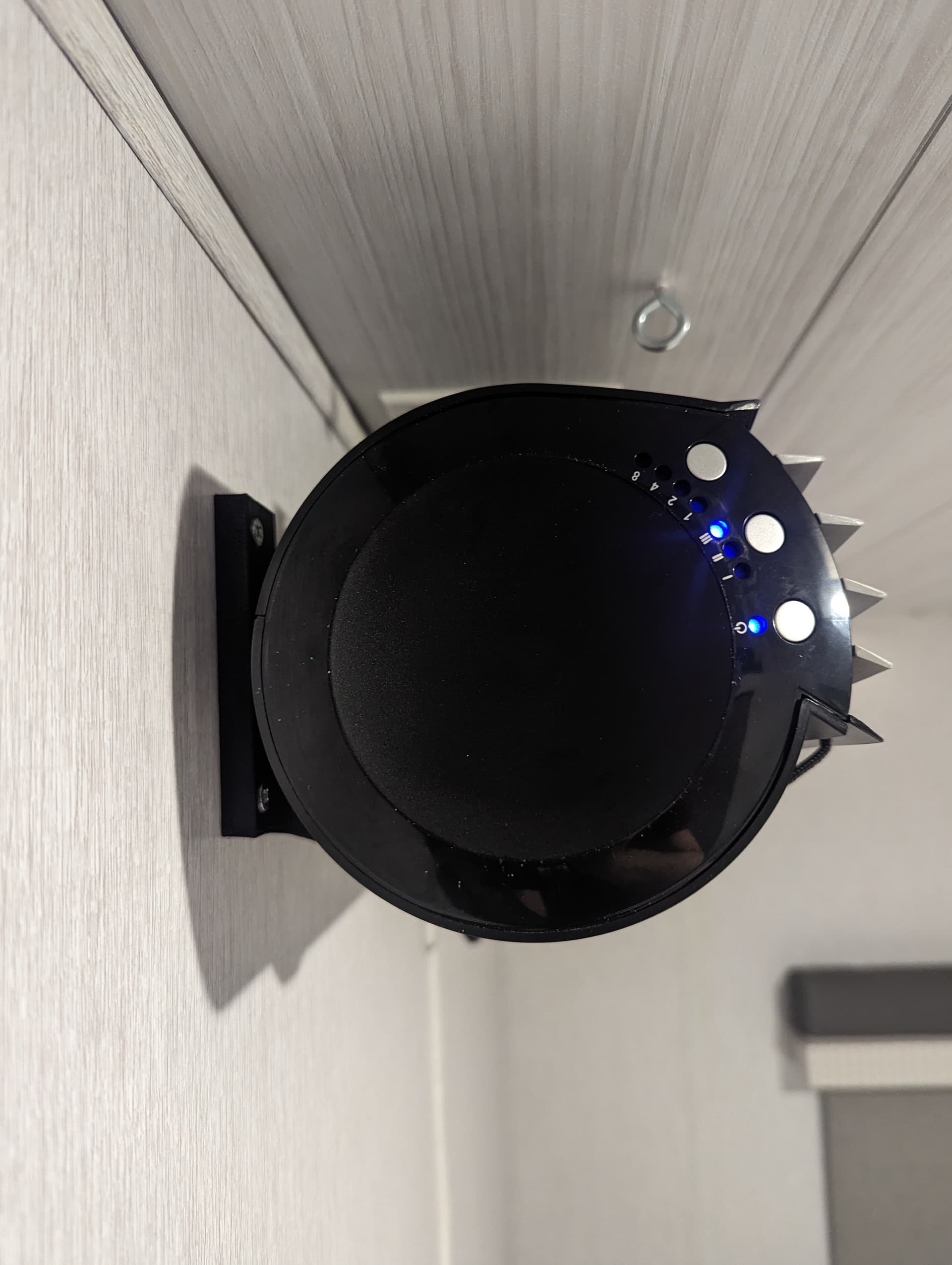
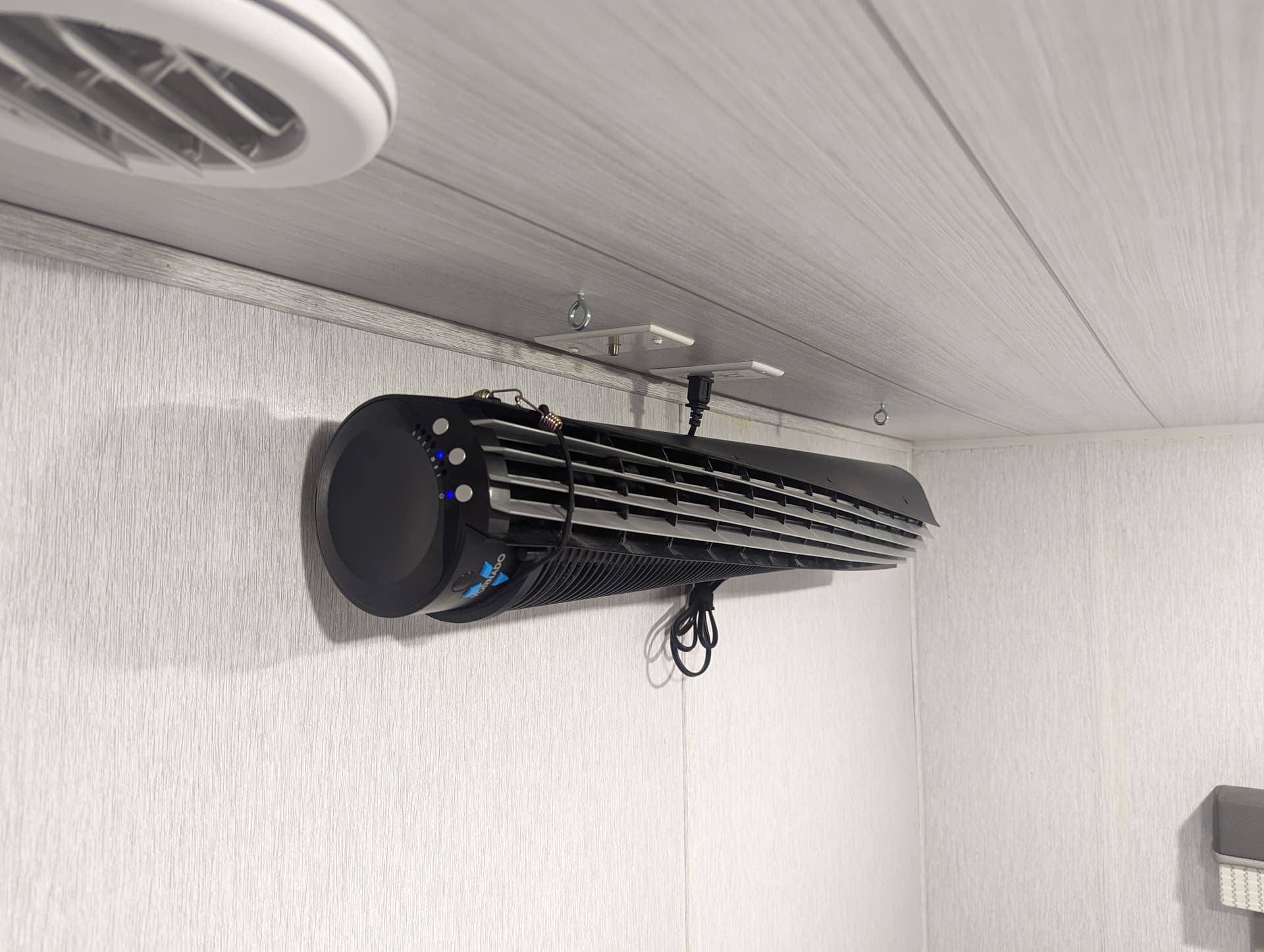
I’m working on a wall mount for a floorstanding vertical fan.
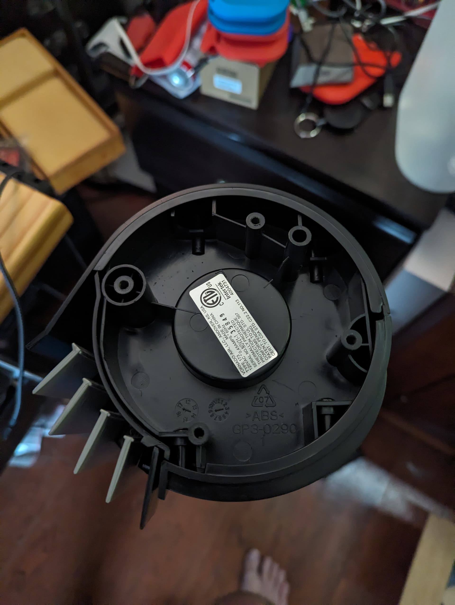
The designers of the fan have a removable stand on the bottom. Great! I can use that to mount one end of my mount.
Sure.
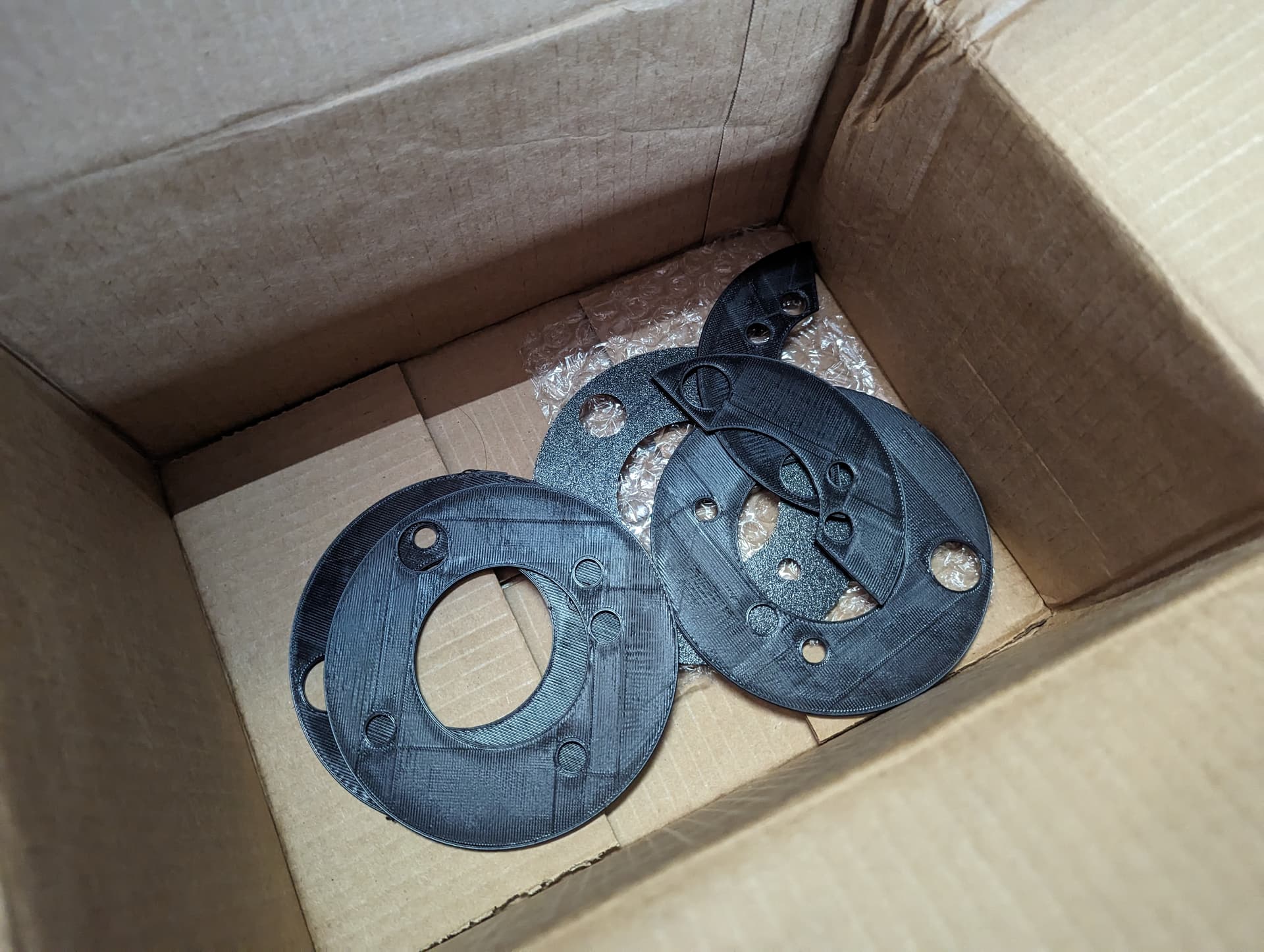
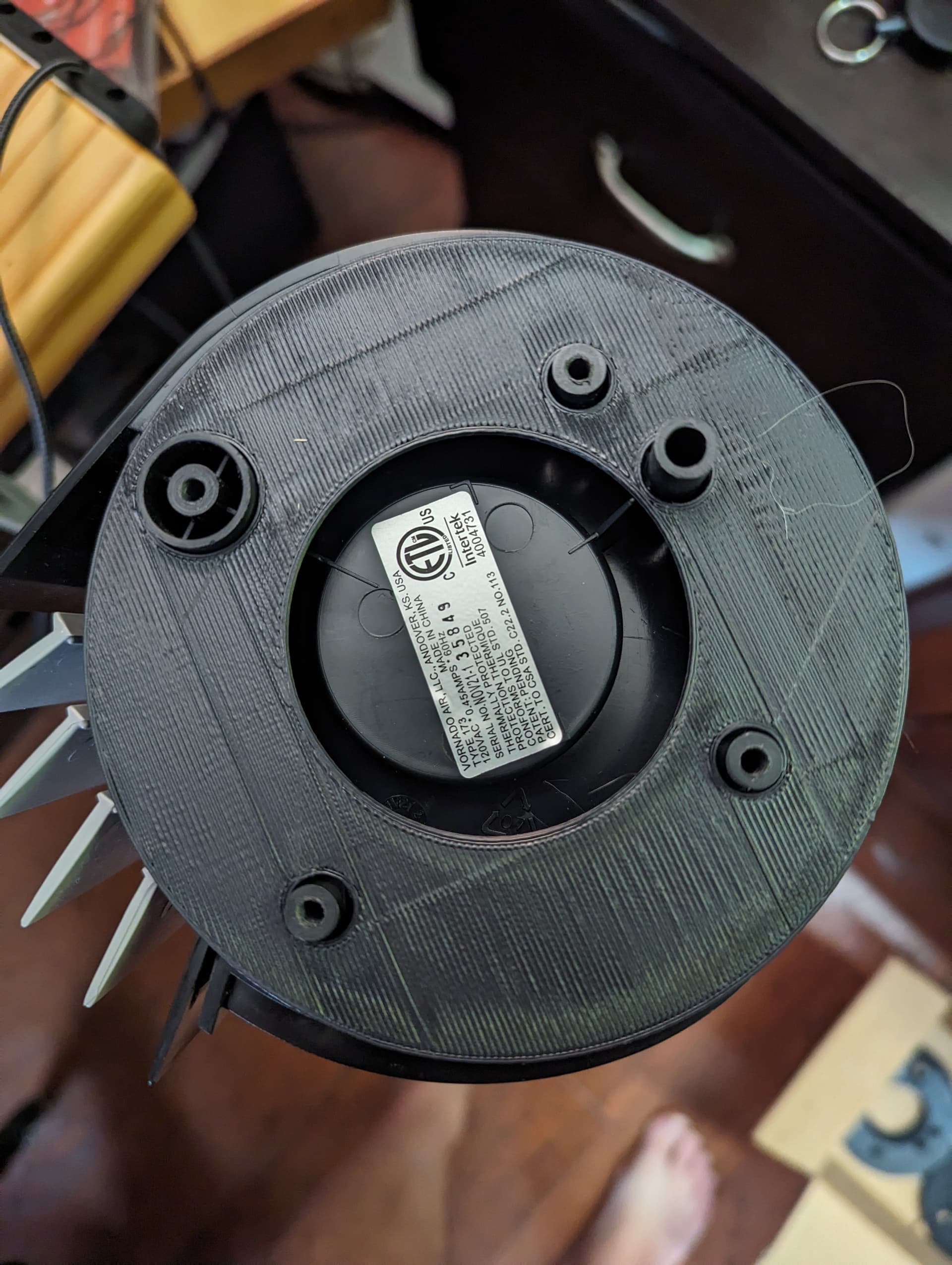
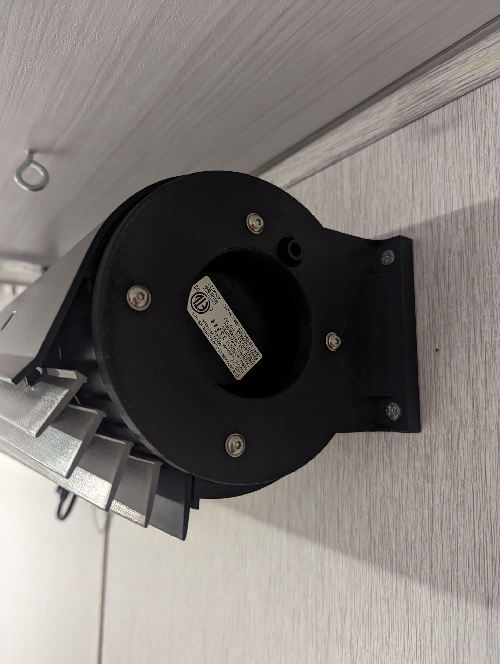
9 iterations later, I think I finally have the holes lining up. None of these holes are directly across from each other or even at the same distance from ‘center’ of the device.
What I ended up doing is making a circle template large enough to go around all the holes. Then use offsets from the outside edge to get a starting point for each hole. Lastly I picked one hole as the reference point and measured the distance from it to the other holes to move them around their circle to the correct location.
The first 3 holes lined up perfect first try. The last two holes took maximum effort
Why did they design it this way?
I have the same issue with pcb designers that stick mounting holes at random distances from edges. At least a few companies are providing decent mounting diagrams now.
haha! I went down this rabbit hole way too many times
You live you learn ^^
Let’s say it’s still an interesting lesson about how to get references/measurments out of a “kinda round” shape, which might also come in handy at some time
Just as an aside, here are a couple of posts on the topic of straightening photos - just including them now after fact in case someone finds them and can use them.