I started looking into this a few weeks ago. After doing a bit of research & watching some youtube videos on using the fusion 360 API it seems within my reach now. I have been using these openscad thread modules OpenSCAD threads that allow me to customize threads extensively. I was initially going to look at converting this code from openscad to python. It turned out the formula for the thread profile is pretty simple to generate a single profile. I used this page for reference. ISO metric screw thread - Wikipedia
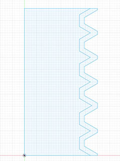
I created a spreadsheet to calculate all the variables, then I rewrote these in openscad to generate a thread profile. Here is what it looks like in profile with a M6 thread & 5.6mm thread. This would give 0.2mm clearance around the threads.
While looking for ideas for fusion 360 scripts on GitHub, I came across this one that uses custom threads with the standard fusion 360 thread feature. It uses an XML file to add an option for 3D-printed Metric Threads to the list which allows for several different clearance options. This essentially does what I want, but not quite. You can add your own customized thread diameters, but you cannot change the pitch. Here is the link to that script if someone would like to use it.
I want to create a fusion 360 python script that askes for Thread Diameter, Pitch, Thread length & Angle. What this program will do is create a sketch of a single Thread in profile & a helix of the minimum diameter for the path for the sweep. After manually drawing this for testing, I also need to repeat this same helix for the top part of that inside thread profile for the guide rail. I drew the screw profile & helix in an AutoCAD clone & imported into fusion 360 in a sketch. I made sure 3d sketch was turned on. Now I just need to figure out the coding. I got ChatGPT to draw a helix correctly in AutoCAD lisp but was not quite right when it generated it for fusion 360’s python code. I just need to understand the syntax better. Here is what that test looked like.
Here is the OpenSCAD source for drawing the screw profile. I made it a module so I could call it twice & see the difference in threads for clearance. As you can see from the image in 1st post, you can’t really get an offset the same amount all the way around the threads. In my example I used a thread diameter of 6.0mm & 5.6mm. If you offset the threads inward instead of using a different thread diameter you would get a vertex point for a .2mm offset of the thread instead of line segment for the outer thread. Here is what the offset would look like when offset inward. Offset outward would have the same affect but the inner diameter would have a vertex instead of the outer.
Here is the OpenSCAD source I created to test the screw thread profiles if someone wants to examine this further.
//M6 thread Calcs by: David Bunch 4/9/2024
//
module M_Threads(OD = 6.0, Pitch = 1.0, Ang = 30.0, Ht = 5, LH = 1)
{
T_Ang = tan(Ang); //Tangent of Thread Angle
Rad = OD / 2; //Radius of Major Diameter
H_Thread = (1 / T_Ang)*(Pitch / 2); //Total Height of thread vertex to vertex
H4 = H_Thread / 4; //distance from inner vertex to inner thread
H8 = H_Thread / 8; //distance from outer vertex to outer thread
H_5H8 = (5 * H_Thread) / 8; //Height of actual thread
H_3H8 = (3 * H_Thread) / 8; //distance from outer thread to pitch diameter
H3 = (H_5H8 + H8) * T_Ang; //Y distance to ends of inner thread line
P4 = Pitch / 4;
P8 = Pitch / 8;
D_Min = OD - (2 * H_5H8);
R_Min = D_Min / 2;
D_Pit = OD - (2 * H_3H8);
Tot = Ht / Pitch;
difference()
{
union()
{
translate([-R_Min,0,0])
cube([D_Min,Ht,LH]); //Draw cube for thread profile view
for (m = [0,1])
{
mirror([m,0,0])
for (i = [0:Tot])
{
translate([0,i,0])
Tooth(); //Draw all the threads on both sides
}
}
}
translate([-10,-10,-1])
cube([20,10,10]); //cut out half of bottom threads
translate([-10,Ht,-1])
cube([20,10,10]); //cut out half of top threads
}
module Tooth()
{
linear_extrude(height = LH, center = false, convexity = 10)polygon(points =
[[R_Min,-H3],[Rad,-P8/2],[Rad,P8/2],[R_Min,H3]]);
}
}
M_Threads();
color(“red”) //6.0 - 5.6 = 0.4 / 2 = 0.2mm clearance around outer & inner thread diameters
M_Threads(5.6,1,30,5,2);
Thank you for this topic and all the python based Fusion addin info.
Curious what you’re looking to create/do? Seems like customizing clearance could be done using push-pull surface operation in Fusion. But, given…
Sounds like you’re looking to do something more unusual/interesting? Are you looking to create less typical screw thread profiles that are optimized for 3D printing, and/or have other characteristics? For example instead of typical…
Are you also considering asymmetrical, more load bearing, and less overhanging profiles that are easier to 3D print like…
Vaguely recall seeing someone make custom threads with thread’s upper profile flat to help resist downward force/weight. Some self printing printer project with custom thread profile with negative thread angle to pull ‘bolt’ towards partially sweeped ‘nut’. Don’t know if there’s an official name for this, have been calling them “Cleat threads”.
The push pull would work with standard 30-degree angle threads that the fusion 360 thread feature uses, but I would like to use 40-degree for less overhang printing problems. The threads I want are more geared towards 3D printing. Since 3D printing has been around for quite a while now, I don’t understand why Autodesk does not have an easy option to do allow for a tolerance. They do it with gears with the backlash.
I had not thought about doing the asymmetrical threads, but that should be doable.
I am looking to be able to do threads the same way as I do in openscad with the thread module I am using that I referenced in 1st message. All the parameters for that are:
metric_thread (diameter=OD, pitch=Pit, length=Thread_Ht, internal=false, angle = 40, thread_size = Pit, n_starts=1);
The only ones that I ever use are diameter, pitch, length & angle. So initially that is all I plan to use. The OpenSCAD thread module also does English threads. From looking at his code, he just does the conversion from English to metric & then calls the metric module.
I just got fusion to draw a helix using a 3D spline with python code. ChatGPT helped me with that. It didn’t create the code correctly for fusion, but it did for AutoCAD lisp. Since I know lisp pretty well, I was able to convert the logic to python. The next step should be easy which is to add the screw profile. The last part might take me a little time which is to have an input dialog for all the values. I should be able to look at the spur gear python script to see how to do this.
I found this fusion python code sample that did the 3D splines. Fusion Help | Sketch Sample API Sample | Autodesk
I don’t understand at all what the purpose of the script is, so forgive me for my naive approach.
In Onshape, I either use a standard thread (I’ve discovered metric threads print well) or make my own profile to suit whatever I’m doing.
The “secret sauce” is simply to use a Boolean subtract with a 0.2mm gap. It’s an easily repeatable and semi automated process, which I assume would be similar in F360 - just a case of locating as many instances of the threaded part in their correct place before making the subtraction.
Is it easy to explain to me what the benefit of the script is?
Those are pretty expensive fidgets. I guess people buy them for the novelty or as practical jokes.
I’m probably just a little off my rocker. It is just that I am used to doing threads a certain way in OpenSCAD & I wanted the same functionality. I can probably print ok with 30 degree angles, but would like the option to change that. I am also learning quite a bit going through this process & my destination might end up in a different spot than I originally thought.
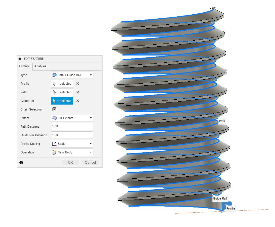
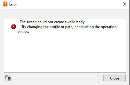
I might have to shelf my idea for now. I can get the helix drawn using 3D splines using the API & I can get it to do the sweep using the profile, but it also needs the Guide Rail added or the threading gets wonky. Here is the error message from that.
It’s interesting that I can import a DXF file with a helix drawn in an AutoCAD clone & it will work. It does have to be an AutoCAD 2000 DXF or later to get the helix. DXF versions 13 & 14 export as a 3D spline. DXF version 12 & earlier export this a 3D polyline. It is also interesting that the splines in the version 13 or 14 DXF file will work. Those splines only have 43 total control points for 5 turns which looks to be 8 points per revolution. It has an extra point after the beginning point and before the last point. If I trace those 8 points in fusion, it looks like a circle.
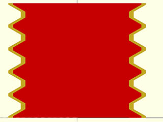
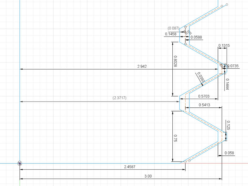
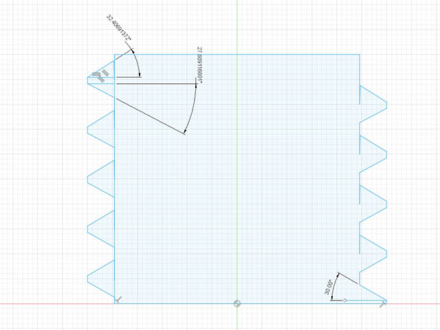
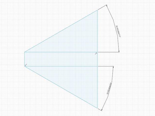
I also learned something else about these threads. Those familiar with threads will already know this, but in Fusion, the male threads have a class 6G & the female threads have a class 6H which has a little bit of tolerance built in. I measured the differences to see how much tolerances that have. The dashed line is M6 thread that I drew from the equations. The inner blue lines are the male threads & the outer blue lines are the female threads.
Using that center line as the guide rail along with using the inner edge of a triangular spiral from the coil will work. If I just add a centerline for the guide rail. I tried this in conjunction with the helix I created & it worked. Now I just have to figure out how to extrude that using the API. I don’t use threads very often, so just manually drawing these after getting the helix & profile automatically created would not be too bad. Fusion Help | How to create a 3D sketch spiral or helix in Fusion | Autodesk
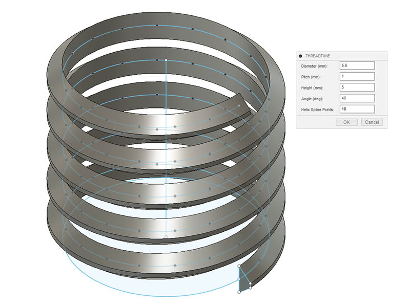
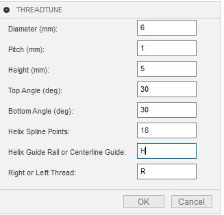
I have this program working now. I used ChatGPT to help me come up with a name for it. From its choices, I thought ThreadTune sounded good. I just a the basic parameters in the dialog for now. I will add another option for asymmetrical threads like @azab2c mentioned as well as a check box for right- or left-hand thread. I found 18 spline points per revolution sufficient for a smooth helix. 9 is probably good enough but added an option to change that. I have not been able to get it to extrude the inner cylinder for the threads but do have the sketch circle in place. I originally had all the sketch lines in one sketch plane but seemed better to have a separate sketch for the thread profile. You don’t have to have Allow 3D sketching of lines and splines turned on the preferences to draw 3D lines using the API. I want to add some more bells & whistles to the dialog if I can, but here is what it looks like so far.
I have this code worked out enough to release it. One thing I have not figured out is how to test which radio button was selected for right- or left-hand threads. I can select either one in the dialog box but have not found any sample code as to how to access which was selected so I can test it. I can get around that problem for now with just a text box to enter R or L until I figure it out.
Another odd behavior I noticed with this API were the negative & positive Y coordinates seemed backwards. There is probably something I am missing here, but looking a profile of a thread, I had to make the negative Y coordinates positive for it to put the point below the X-axis & negative for the Y coordinates that are above the axis. It took me a while to figure that one out as it was not something I expected.
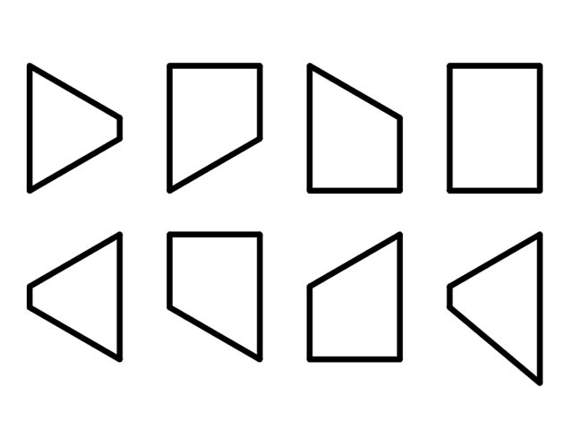
I will see if I can get around to releasing this code on GitHub one day this week. I have it covering most types of odd threading one might consider & you can use any diameter you want. You can also go back & adjust the thread profile in the sketch if you want to do something else to it. A 0 (zero) value for the Top and/or the Bottom angle will make it a horizontal thread. A negative value for the Top and/or Bottom angle will have the thread angle going the opposite direction. The negative one is rather odd, but @azab2c linked a video earlier in this thread where someone used a negative thread value. Here are profiles showing the possibilities.
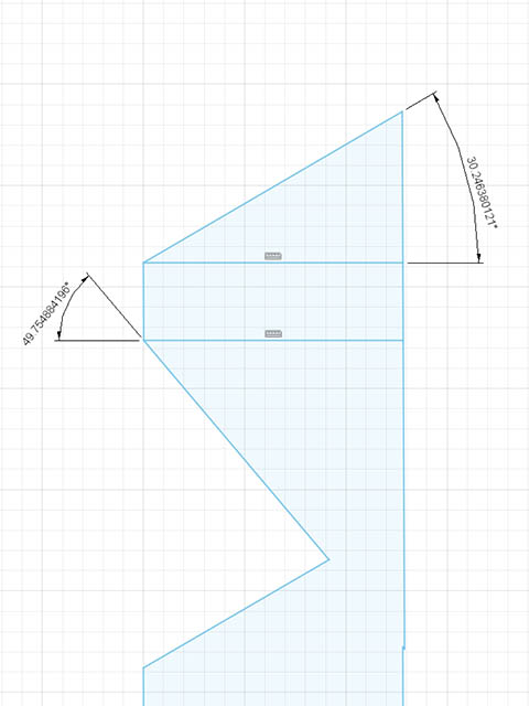
While putting this together to upload, I noticed a couple more problems I did not see until looking at a section cut & putting some dimensions in. First thing, the threads had a gap of .016mm after 4.5 revolutions of the thread which meant both sides of sweep were not following the thread exactly. I also noticed the thread angle was off more and more as it went up which is related to the same problem. After playing with different guide rail methods. I decided on using the helix path at the start of the inside bottom of thread. The guide rail path, I drew another helix following the outside bottom edge. Doing that broke the inverted threading. Now I am using the path at the center point of inside thread & the guide rail at the center point of the outside thread. If the top & bottom angles are not the same, it is not really the center. I will see if that broke anything else.
I also shifted the inside thread in .1mm to make sure it does not have that gap, although that gap would probably be less since I changed the guide rail from the vertical line to the outside helix line.
Here is what that gap & angle difference looked like after 4.5 revolutions of the thread before the fix.
I added an option in the dialog box to use either the outside helix for the guide rail or a vertical centerline. When playing with different spline point resolutions, 45 points gives pretty good accuracy when using the centerline. It just takes a few more seconds to run the program. The reason I started looking into this was using the outside helix for the guide rail broke the part of the program where you entered a different angle for both the bottom & top angle. Using the center line vertical line for the guide rail doesn’t break it.
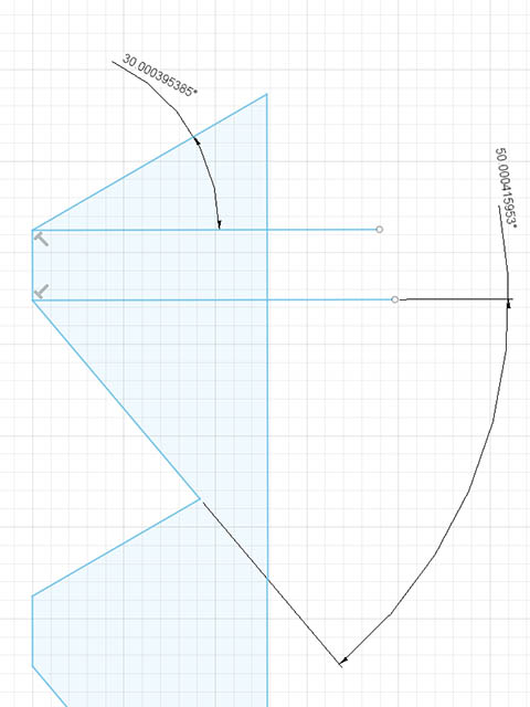
Here is what the difference in accuracy of a 30.0-degree angle & 50-degree angle which use 36 spline points per revolution & 45 spline points.
But interesting enough, using the same angle for both top & bottom like this dialog box is set & use only 18 spline points & the outside helix for the guide rail, I can get decent accuracy. These are all measured after 4.5 revolutions of the thread profile.
I published this program on github located here: GitHub - geodave810/ThreadTune: Fine-Tune your Screw Thread Designs in Autodesk Fusion 360
There are a few things I will probably update over time & probably need to add more to the readme file. Hopefully I gave enough info as to how to set this up for initial use. If anyone tries it, let me know how it works for you.
I did find one big problem I need to fix. Pitch other than 1.0 is not working.
[edit]
It was actually an easy fix that I should have caught before. Guess I was just looking at too many problems. I was multiplying the height and the pitch & should have dividing height / pitch.
I am slowly making progress with adding more features to this. I will probably release the next version this week. After some trial & error, I am now able to join the inner cylinder of the threads & cut the bottom & top edges of the threads off. I have started separating the code into functions to make it easier to read & modify. I also want to save the dialog responses to a text file & use those as the default when it is run the next time. I cheated some using ChatGPT, but the code it generates never runs as is, so have to correct its minor mistakes. As I learn python better, it is easier to write this code. The reason I find ChatGPT very useful for this is there is not a lot of sample code for specific things I want to do.
One interesting thing I have noticed with drawing the helix is where the slowdown is. It doesn’t really slow down much until you use 45 spline points per revolution of the helix. I thought it would be slowing down inside the while loop. After printing a message box after the loop to show how many times it actually looped, it was not that slow. It was actually creating the sweep. If Autodesk ever adds a helix primitive to the sketch, this will be easier.
Another option I would like to add to this is have a drop down of the different standard Metric thread sizes & use those a starting point for the user to edit the thread sizes. I might also add another separate add-in that does both the bolt & nut, although in a lot cases the threading is not attached to any standard type of bolt or nut.
Save dialog input settings to use when program is run next time.
I also added an elapsed timer, but have it commented out for the release. This gives me an idea of how different parameters affect the speed. Mostly the number of spline points & the height are what affect the speed the most which is no surprise. I do have an idea to speed this up & that is to draw just one revolution the threads & duplicate them however many times are needed for the height specified. Since the taller the height, the longer it takes fusion to calculate the sweep. I manually tested it & it does work. Just a matter if I can do this easily within the API or not.
I am really liking this ChatGPT for figuring out all the trivial details needed for some of the coding in fusion360. I usually have to fix some of it, but it gets a lot of it right.
I wanted to draw a hex bolt with these threads & needed to write the code for drawing the hexagon, but also wanted to be able to draw any number of sides to a polygon & not be limited to 6 sides.
I asked it “in fusion 360 python api draw a sketch of a regular polygon with variable number of sides using line segments with 10mm distance between flats”. It actually used the radius from center to each vertex instead of the distance between flats, but the math for that was easy. There may have been a better way to word that also. I ran this routine with a half dozen different sides & it worked perfectly.
This is the code it generated for the routine. The side_length variable is actually the Radius.
import adsk.core, adsk.fusion, adsk.cam, traceback
import math

def draw_regular_polygon(sketch, num_sides, side_length):
    # Calculate the coordinates of the polygon's vertices
    angle_offset = math.pi / num_sides
    vertices = []
    for i in range(num_sides):
        angle = angle_offset + i * (2 * math.pi / num_sides)
        x = side_length * math.cos(angle)
        y = side_length * math.sin(angle)
        vertices.append(adsk.core.Point3D.create(x, y, 0))

    # Draw lines connecting the vertices
    lines = []
    for i in range(num_sides):
        start_point = vertices[i]
        end_point = vertices[(i + 1) % num_sides]
        lines.append(sketch.sketchCurves.sketchLines.addByTwoPoints(start_point, end_point))

    return lines
100%. Used ChatGPT to help accelerate ramping up on Fusion’s Python APIs, felt way faster than sifting docs/web. Was ~yr ago, resulting generated code was great to helping to understand their object model and apis. Generated code needed some changes/fixes, guessing it’s even better now, and exponentially better in the future after most commercial spaces and residential housing switch to being heated by GPUs.
Personally appreciate reading your updates on your flexible thread experimenting. Am thinking of project(s) to make use of in, cheers!